ABS RENAULT KANGOO 1997 KC / 1.G Foult Finding - Injection Workshop Manual
[x] Cancel search | Manufacturer: RENAULT, Model Year: 1997, Model line: KANGOO, Model: RENAULT KANGOO 1997 KC / 1.GPages: 363
Page 18 of 363
DPCF01 1.0
LUCAS DIESEL INJECTION
Fault finding - Interpretation of XR25 bargraphs13
AFTER REPAIRErase the computer memory (G0**), switch the ignition off, then carry out a road
test.
Finish the operation by checking using the XR25.
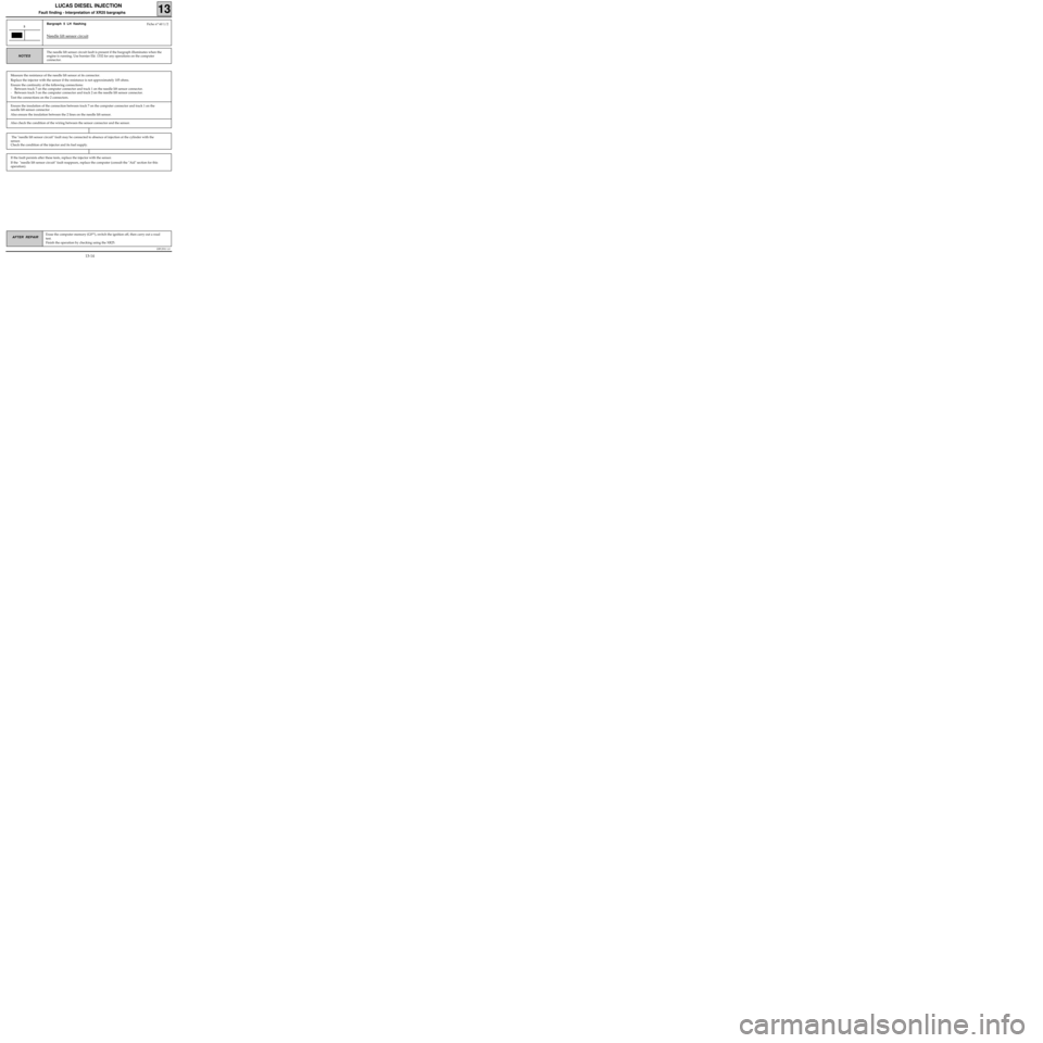
Bargraph 5 LH flashing
Needle lift sensor circuit
5
The needle lift sensor circuit fault is present if the bargraph illuminates when the
engine is running. Use bornier Elé. 1332 for any operations on the computer
connector.
NOTES
Measure the resistance of the needle lift sensor at its connector.
Replace the injector with the sensor if the resistance is not approximately 105 ohms.
Ensure the continuity of the following connections:
- Between track 7 on the computer connector and track 1 on the needle lift sensor connector.
- Between track 3 on the computer connector and track 2 on the needle lift sensor connector.
Test the connections on the 2 connectors.
Fiche n° 60 1/2
Ensure the insulation of the connection between track 7 on the computer connector and track 1 on the
needle lift sensor connector .
Also ensure the insulation between the 2 lines on the needle lift sensor.
Also check the condition of the wiring between the sensor connector and the sensor.
If the fault persists after these tests, replace the injector with the sensor.
If the "needle lift sensor circuit" fault reappears, replace the computer (consult the "Aid" section for this
operation).
The "needle lift sensor circuit" fault may be connected to absence of injection at the cylinder with the
sensor.
Check the condition of the injector and its fuel supply.
13-14
Page 37 of 363
DPCF01 1.0
LUCAS DIESEL INJECTION
Fault finding - Checking conformity
13
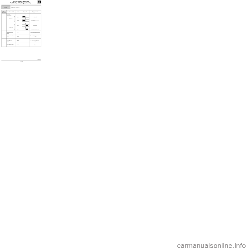
Engine cold, ignition onNOTES
Order of
operationsFunction to check Action Bargraph Display and notes
5Computer
configuration
With AC
Without ACG50*3*
G50*8*
G50*4*
G50*9*With AC
With PAS with pump
Without AC
With conventional PAS
6Absolute pressure
sensor#16 X = local atmospheric pressure
7Coolant temperature
sensor#02 X = Ambient temperature
± 5 °C
8Air temperature
sensor#03 X = Ambient temperature
± 5 °C
9EGR solenoid valve
#24 X = 0
18
18
19
19
13-33
Page 44 of 363
DPCF01 1.0
LUCAS DIESEL INJECTION
Fault finding - Fault charts
13
Carry out a road test then check using the XR25.AFTER REPAIR
NOTES
Chart 3NO FAST IDLE WHEN AIR CONDITIONING REQUESTED
Only consult this customer complaint after a complete check using the XR25.
Look for an open circuit or a short circuit to earth on the connection between track 11 on the injection
computer and track 20 on the BE connector for the air conditioning computer ("AC Inj. / fast idle" infor-
mation).
This fault causes the absence of illumination of bargraph 9 LH side "air conditioning requested".
13-40
Page 52 of 363
JF5111.0
INJECTION
Fault finding - Introduction
17
E7J 780
engine
XR25 CHECKING STATUSES AND PARAMETERS
The status and parameter check is aimed at checking the statuses and parameters which do not illuminate
any fault bargraphs if they are outside of permitted tolerance values . This phase allows :
- Faults to be found without the illumination of fault bargraphs which may correspond to a customer
complaint (example : absence of no load information causing an unstable idle speed).
- The correct operation of the injection to be checked and the risk of faults appearing shortly after the
repair to be eliminated.
This section contains fault-finding for statuses and parameters, under their test conditions
(example : fault finding for # 01 ignition on and fault finding for # 01 engine running).
If a status does not operate normally or a parameter is outside of permitted tolerance values, consult the
fault-finding page indicated in the "Fault-finding" column.
XR25 CHECK CORRECT
If the XR25 check is correct, but the customer complaint persists, the problem must be dealt with through
customer complaints.
Treatment of customer complaints
This section has fault charts, which suggest a series of possible causes of the problem.
These lines of enquiry must only be used in the following cases :
- No fault bargraph appears on the XR25.
- No faults are detected during the checking of statuses and parameters.
- The vehicle is not operating correctly
POST-REPAIR CHECK
This operation is a simple check of the repair (by a command, or by an XR25 command mode ...).
This makes it possible to check that the system upon which the intervention has been carried out is correct
electrically.
It is an introduction to the road test.
ROAD TEST
A road test is essential in order to guarantee the correct operation of the vehicle and to test the quality of the
repair. Its role is to make sure that no faults occur (or will occur) when driving.
In order to be significant, the road test is subject to special driving conditions.
17-4
Page 113 of 363
JF5111.0
INJECTION
Fault finding - Checking conformity
17
E7J 780
engine
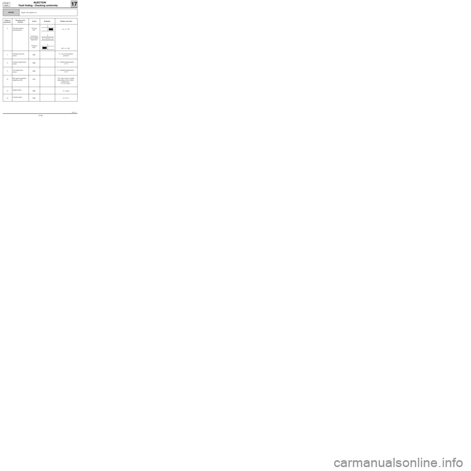
Engine cold, ignition on.NOTES
Order of
operationsFunction to be
checkedAction Bargraph Display and notes
6 Throttle position
potentiometerNo load
# 17
Accelerator
pedal slightly
depressed
Full load
# 17 16 < X < 50
185 < X < 243
7Absolute pressure
sensor# 01 X = Local atmospheric
pressure
8Coolant temperature
sensor# 02 X = Ambient temperature
± 5 °C
9Air temperature
sensor# 03 X = Ambient temperature
± 5 °C
10Idle speed regulation
stepping motor# 12The value read is variable
depending on the coolant
temperature :
7 % ≤ X ≤ 100 %
11Engine speed
# 06 X = 0 rpm
12Canister bleed
# 23 X = 0.7 %
2
2
2
17-65
Page 123 of 363
JSA051.0
INJECTION
Fault finding - Introduction
17
D7F 710
engine -
35 tracks
XR25 CHECKING STATUSES AND PARAMETERS
The status and parameter check is aimed at checking the statuses and parameters which do not illuminate
any fault bargraphs if they are outside of permitted tolerance values . This phase allows :
- Faults to be found without the illumination of fault bargraphs which may correspond to a customer
complaint (example : absence of no load information causing an unstable idle speed).
- The correct operation of the injection to be checked and the risk of faults appearing shortly after the
repair to be eliminated.
This section contains fault-finding for statuses and parameters, under their test conditions
(example : fault finding for # 01 ignition on and fault finding for # 01 engine running).
If a status does not operate normally or a parameter is outside of permitted tolerance values, consult the
fault-finding page indicated in the "Fault-finding" column.
XR25 CHECK CORRECT
If the XR25 check is correct, but the customer complaint persists, the problem must be dealt with through
customer complaints.
Treatment of customer complaints
This section has fault charts, which suggest a series of possible causes of the problem.
These lines of enquiry must only be used in the following cases :
- No fault bargraph appears on the XR25.
- No faults are detected during the checking of statuses and parameters.
- The vehicle is not operating correctly
POST-REPAIR CHECK
This operation is a simple check of the repair (by a command, or by an XR25 command mode ...).
This makes it possible to check that the system upon which the intervention has been carried out is correct
electrically.
It is an introduction to the road test.
ROAD TEST
A road test is essential in order to guarantee the correct operation of the vehicle and to test the quality of the
repair. Its role is to make sure that no faults occur (or will occur) when driving.
In order to be significant, the road test is subject to special driving conditions.
17-78
Page 182 of 363
JSA051.0
INJECTION
Fault finding - Checking conformity
17
D7F 710
engine -
35 tracks
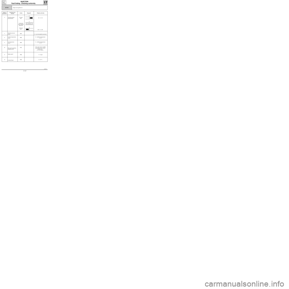
Engine cold, ignition on.NOTES
Order of
operationsFunction to be
checkedAction Bargraph Display and notes
6 Throttle position
potentiometerNo load
# 17
Accelerator
pedal slightly
depressed
Full load
# 17 10 < X < 50
185 < X < 245
7Absolute pressure
sensor# 01
X = Local atmospheric pressure
8Coolant temperature
sensor# 02 X = Ambient temperature
± 5 °C
9Air temperature
sensor# 03 X = Ambient temperature
± 5 °C
10
Idle speed regulation
stepping motor# 12The value read is variable
depending on the coolant
temperature :
11 % ≤ X ≤ 100 %
11Engine speed
# 06 X = 0 rpm
12
Canister bleed# 23 X = 0.7 %
2
2
2
17-137
Page 193 of 363

JSA052.0
INJECTION
Fault finding - Introduction
17
D7F 710
engine -
55 tracks
XR25 CHECKING STATUSES AND PARAMETERS
The status and parameter check is aimed at checking the statuses and parameters which do not illuminate
any fault bargraphs if they are outside of permitted tolerance values . This phase allows :
- Faults to be found without the illumination of fault bargraphs which may correspond to a customer
complaint (example : absence of no load information causing an unstable idle speed).
- The correct operation of the injection to be checked and the risk of faults appearing shortly after the
repair to be eliminated.
This section contains fault-finding for statuses and parameters, under their test conditions
(example : fault finding for # 01 ignition on and fault finding for # 01 engine running).
If a status does not operate normally or a parameter is outside of permitted tolerance values, consult the
fault-finding page indicated in the "Fault-finding" column.
XR25 CHECK CORRECT
If the XR25 check is correct, but the customer complaint persists, the problem must be dealt with through
customer complaints.
Treatment of customer complaints
This section has fault charts, which suggest a series of possible causes of the problem.
These lines of enquiry must only be used in the following cases :
- No fault bargraph appears on the XR25.
- No faults are detected during the checking of statuses and parameters.
- The vehicle is not operating correctly
POST-REPAIR CHECK
This operation is a simple check of the repair (by a command, or by an XR25 command mode ...).
This makes it possible to check that the system upon which the intervention has been carried out is correct
electrically.
It is an introduction to the road test.
ROAD TEST
A road test is essential in order to guarantee the correct operation of the vehicle and to test the quality of the
repair. Its role is to make sure that no faults occur (or will occur) when driving.
In order to be significant, the road test is subject to special driving conditions.
17-150
Page 253 of 363
JSA051.0
INJECTION
Fault finding - Checking conformity
17
D7F 710
engine -
55 tracks
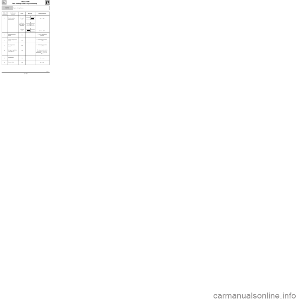
Engine cold, ignition on.NOTES
Order of
operationsFunction to be
checkedAction Bargraph Display and notes
6 Throttle position
potentiometerNo load
# 17
Accelerator
pedal slightly
depressed
Full load
# 17 10 < X < 50
185 < X < 245
7Absolute pressure
sensor# 01 X = Local atmospheric
pressure
8Coolant temperature
sensor# 02 X = Ambient temperature
± 5 °C
9Air temperature
sensor# 03 X = Ambient temperature
± 5 °C
10Idle speed regulation
stepping motor# 12The value read is variable
depending on the coolant
temperature : : 11 % ≤ X ≤
100 %
11Engine speed
# 06 X = 0 rpm
12Canister bleed
# 23 X = 0.7 %
2
2
2
17-210
Page 261 of 363
ABS BOSCH 5.3
FAULT FINDING
CONTENTS
Introduction . . . . . . . . . . . . . . . . . . . . . . . . . . . . . . . . . . . . . . . . . . . . . . . . . . . . . . . . . . . . . . . . . . . . . . . . . . . . . . . . . 01
XR25 fiche . . . . . . . . . . . . . . . . . . . . . . . . . . . . . . . . . . . . . . . . . . . . . . . . . . . . . . . . . . . . . . . . . . . . . . . . . . . . . . . . . . . 02
Interpretation of XR25 bargraphs . . . . . . . . . . . . . . . . . . . . . . . . . . . . . . . . . . . . . . . . . . . . . . . . . . . . . . . . . . . . . 04
Checking conformity . . . . . . . . . . . . . . . . . . . . . . . . . . . . . . . . . . . . . . . . . . . . . . . . . . . . . . . . . . . . . . . . . . . . . . . . . 18
Aid . . . . . . . . . . . . . . . . . . . . . . . . . . . . . . . . . . . . . . . . . . . . . . . . . . . . . . . . . . . . . . . . . . . . . . . . . . . . . . . . . . . . . . . . . 19
Customer complaints . . . . . . . . . . . . . . . . . . . . . . . . . . . . . . . . . . . . . . . . . . . . . . . . . . . . . . . . . . . . . . . . . . . . . . . . . 20
Fault charts . . . . . . . . . . . . . . . . . . . . . . . . . . . . . . . . . . . . . . . . . . . . . . . . . . . . . . . . . . . . . . . . . . . . . . . . . . . . . . . . . . 21Pages