instrument panel RENAULT KANGOO 1997 KC / 1.G Foult Finding - Injection Workshop Manual
[x] Cancel search | Manufacturer: RENAULT, Model Year: 1997, Model line: KANGOO, Model: RENAULT KANGOO 1997 KC / 1.GPages: 363
Page 26 of 363
DPCF01 1.0
LUCAS DIESEL INJECTION
Fault finding - Interpretation of XR25 bargraphs13
AFTER REPAIRErase the computer memory (G0**), switch the ignition off, then carry out a road
test.
Finish the operation by checking using the XR25.
Bargraph 10 LH flashing
Fault warning light circuit
XR25 aid:*10 : cc.1 : Short circuit to 12 volts
10
Even if present at the moment of testing, this fault is still declared by a flashing
BG 10LH side. To confirm its presence and the necessity of following the fault fin-
ding below, erase the computer memory then start command mode G21*1*.
The fault is present if the bargraph flashes again.
Use bornier Elé. 1332 for any operations on the computer connector.
NOTES
Fiche n° 60 1/2
cc.1
Ensure insulation in relation to 12 volts of the connection between track 18 of the computer connector
and the instrument panel warning light (track 6 on connector MA).
Test at the warning light bulb (bulb in short circuit).
None NOTES
13-22
Page 27 of 363
DPCF01 1.0
LUCAS DIESEL INJECTION
Fault finding - Interpretation of XR25 bargraphs13
AFTER REPAIRErase the computer memory (G0**), switch the ignition off, then carry out a road
test.
Finish the operation by checking using the XR25.
Bargraph 10 RH illuminated (Co.0) or flashing (cc.1)
Preheating warning light circuit
XR25 aid:*30 :cc.0 : Open circuit or short circuit to earth
cc.1 : Short circuit to 12 volts
10Fiche n° 60 1/2
co.0
Check the condition of the preheating warning light bulb then the presence of +after ignition feed at
the warning light.
Ensure the continuity and insulation in relation to earth of the connection between track 9 of the
computer connector and the instrument panel preheating warning light (track 5 on CY connector).
Test the connections on the computer connector.
None NOTES
cc.1
Ensure insulation in relation to 12 volts of the connection between track 9 of the computer connector
and the instrument panel preheating warning light (track 5 on connector CY).
Test at the preheating warning light bulb (bulb in short circuit).
Use bornier Elé. 1332 for any operations on the computer connector.NOTES
Even if present at the moment of testing, this fault is still declared
by a flashing BG 10RH side. To confirm its presence and the necessity
of following the fault finding below, erase the computer memory
then start command mode G21*2*.
The fault is present if the bargraph flashes again.
NOTES
13-23
Page 32 of 363
Bargraphs 9 RH and 9 LH side
Air conditioning
XR25 aid :BG 9LH illuminated if AC requested
BG 9RH illuminated if AC authorised
DPCF01 1.0
LUCAS DIESEL INJECTION
Fault finding - Interpretation of XR25 bargraphs13
AFTER REPAIR
Bargraphs 5 and 6 RH and LH sides
Relay control5
None NOTES
These bargraphs visualise the control of the various relays:
- Preheating relay N° 1.
- Preheating relay N° 2 (not used).
- Power assisted steering pump assembly relay (for AC + PAS).
- Altimetric corrector relay.
Fiche n° 60 2/2
6
Ensure the bargraphs operate correctly
9Fiche n° 60 2/2
If
BG 9LH is extinguished when AC is requested, ensure the continuity and insula-
tion of the connection between track 11 of the diesel computer connector and
track 20 of the AC computer connector.
NOTES
Bargraph 10 LH side
Warning light control
XR25 aid :BG 10LH is illuminated if the warning light on the instrument panel
is controlled. This bargraph is normally illuminated; it extinguishes
when the engine is running if there is no fault.
10Fiche n° 60 2/2
None
NOTES
13-28
Page 103 of 363
Connect the bornier in place of the computer and check the insulation and continuity of the line:
Computer 43 6 Instrument panel
Repair.
JF5111.0
INJECTION
Fault finding - Status and parameter interpretation17
E7J 780
engine
AFTER REPAIRStart the status and parameter check again from the beginning.
DIAG 19
Fiche n° 27
FAULT WARNING LIGHT CIRCUIT
XR25 aid:None
No fault bargraphs should be illuminated.NOTES
Check the condition of the warning light and its feed.
Repair if necessary.
17-55
Page 142 of 363
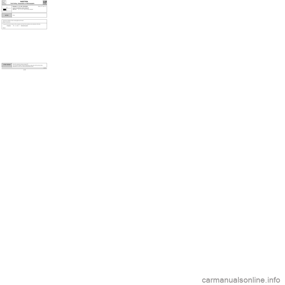
Connect the bornier in place of the computer and check the insulation and continuity of the line:
Computer 19 6 Instrument panel
Repair.
JSA051.0
INJECTION
Fault finding - Interpretation of XR25 bargraphs17
D7F 710
engine -
35 tracks
Erase the computer memory using G0**.
Try to start the engine. Switch the ignition on, then deal with the other faults.
Remember to carry out a status and parameter check.AFTER REPAIR
Bargraph 12 LH side illuminatedFiche n° 27 side 1/2
FAULT WARNING LIGHT CIRCUIT
XR25 aid:CO, CC- or CC+ line 19 of the computer
12
NoneNOTES
Check the condition of the warning light and its feed.
Repair if necessary.
17-97
Page 172 of 363
Connect the bornier in place of the computer and check the insulation and continuity of the line:
Computer 19 6 Instrument panel
Repair.
JSA051.0
INJECTION
Fault finding - Status and parameter interpretation17
D7F 710
engine -
35 tracks
AFTER REPAIRStart the status and parameter check again from the beginning.
DIAG 18
Fiche n° 27
FAULT WARNING LIGHT CIRCUIT
XR25 aid:None
No fault bargraphs should be illuminated.NOTES
Check the condition of the warning light and its feed.
Repair if necessary.
17-127
Page 212 of 363
Connect the bornier in place of the computer and check the insulation and continuity of the line.
Computer 43 6 Instrument panel
Repair.
JSA052.0
INJECTION
Fault finding - Interpretation of XR25 bargraphs17
D7F 710
engine -
55 tracks
Erase the computer memory using G0**.
Try to start the engine. Switch the ignition on, then deal with the other faults.
Remember to carry out a status and parameter check.AFTER REPAIR
Bargraph 12 LH side illuminatedFiche n° 27 side 1/2
FAULT WARNING LIGHT CIRCUIT
XR25 aid:CO, CC- or CC+ line 43 of the computer
12
NoneNOTES
Check the condition of the warning light and its feed.
Repair if necessary.
17-169
Page 243 of 363
Connect the bornier in place of the computer and check the insulation and continuity of the line:
Computer 43 6 Instrument panel
Repair.
JSA052.0
INJECTION
Fault finding - Status and parameter interpretation17
D7F 710
engine -
55 tracks
AFTER REPAIRStart the status and parameter check again from the beginning.
DIAG 19FAULT WARNING LIGHT CIRCUITFiche n° 27
XR25 aid:None
No fault bargraphs should be illuminated.
NOTES
Check the condition of the warning light and its feed.
Repair if necessary.
17-200
Page 282 of 363
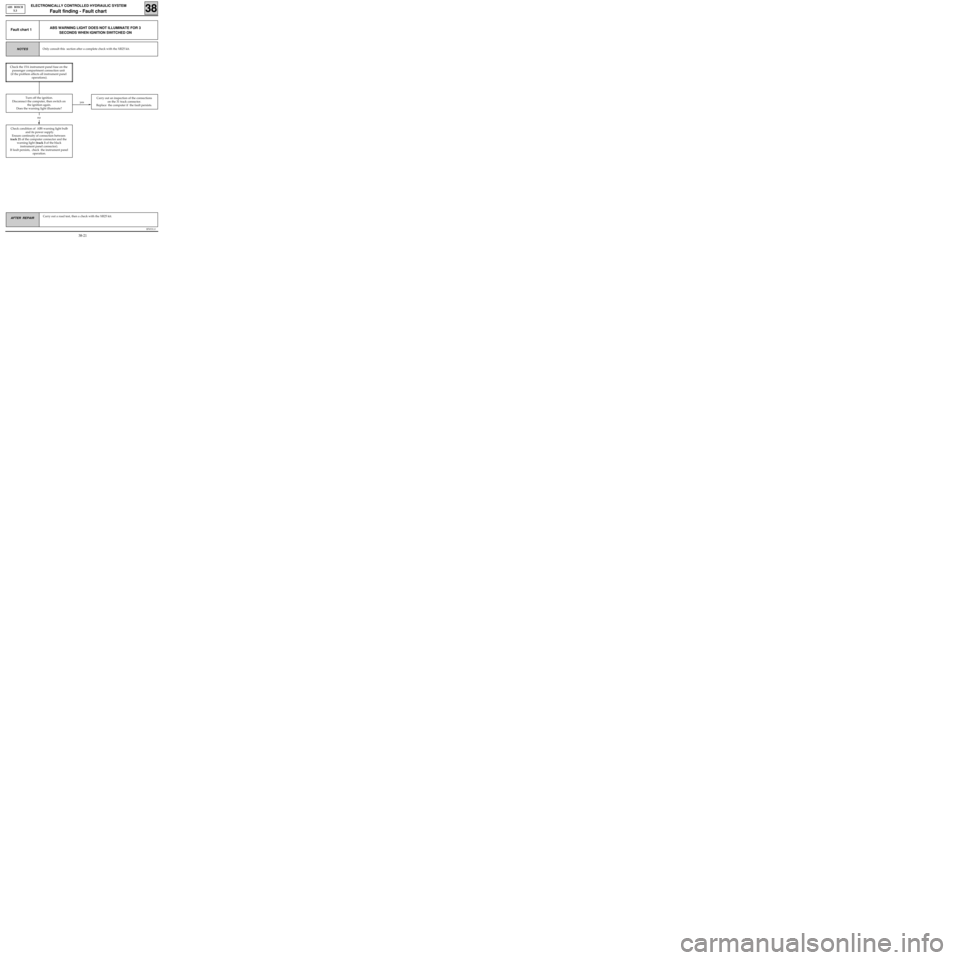
B76531.0
ELECTRONICALLY CONTROLLED HYDRAULIC SYSTEM
Fault finding - Fault chart 38
ABS BOSCH
5.3
AFTER REPAIR Carry out a road test, then a check with the XR25 kit.
yes
ABS WARNING LIGHT DOES NOT ILLUMINATE FOR 3
SECONDS WHEN IGNITION SWITCHED ONFault chart 1
Only consult this section after a complete check with the XR25 kit.NOTES
Check condition of ABS warning light bulb
and its power supply.
Ensure continuity of connection between
track 21 of the computer connector and the
warning light (track 3 of the black
instrument panel connector).
If fault persists, check the instrument panel
operation.
Carry out an inspection of the connections
on the 31 track connector.
Replace the computer if the fault persists.
no
Check the 15A instrument panel fuse on the
passenger compartment connection unit
(if the problem affects all instrument panel
operations).
Turn off the ignition.
Disconnect the computer, then switch on
the ignition again.
Does the warning light illuminate?
38-21
Page 283 of 363
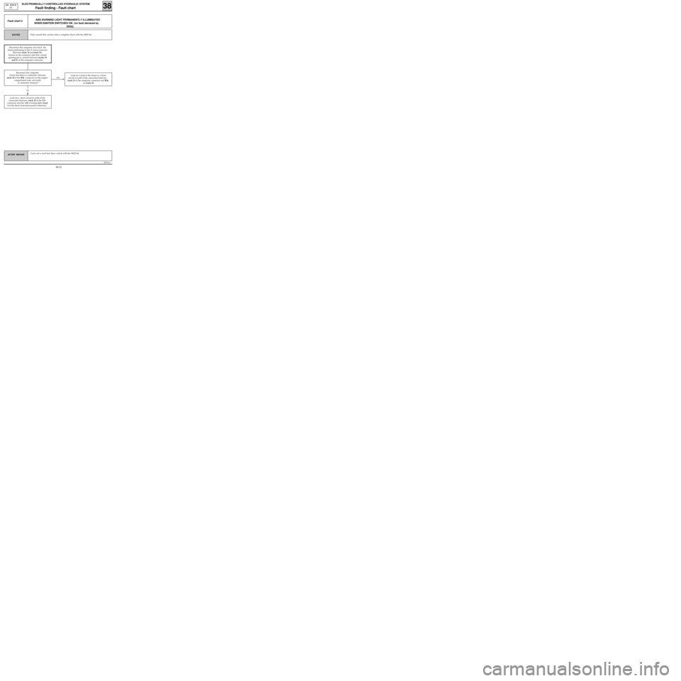
B76531.0
ELECTRONICALLY CONTROLLED HYDRAULIC SYSTEM
Fault finding - Fault chart 38
ABS BOSCH
5.3
AFTER REPAIR Carry out a road test, then a check with the XR25 kit.
ABS WARNING LIGHT PERMANENTLY ILLUMINATED
WHEN IGNITION SWITCHED ON (no fault declared by
XR25)Fault chart 2
Only consult this section after a complete check with the XR25 kit.NOTES
yes
Look for a short circuit to earth of the
connection between track 10 of the R36
connector and the ABS warning light (track
3 of the black instrument panel connector).Look for a fault in the shunt or a short
circuit to earth of the connection between
track 21 of the computer connector and R36
on track 10.
no
Disconnect the computer and check the
shunt positioning in the 31 track connector
(between track 19 and track 21).
Ensure on the computer side that a shunt
opening pin is present between tracks 19
and 21 of the computer connector.
Reconnect the computer.
Check that there is continuity between
track 10 of the R36 connector on the engine
compartment side, and earth.
Is continuity ensured ?
38-22