diagram RENAULT KANGOO 1997 KC / 1.G Sheet Metal Work Workshop Manual
[x] Cancel search | Manufacturer: RENAULT, Model Year: 1997, Model line: KANGOO, Model: RENAULT KANGOO 1997 KC / 1.GPages: 255
Page 13 of 255
GENERAL
Using symbols
40
11644R1
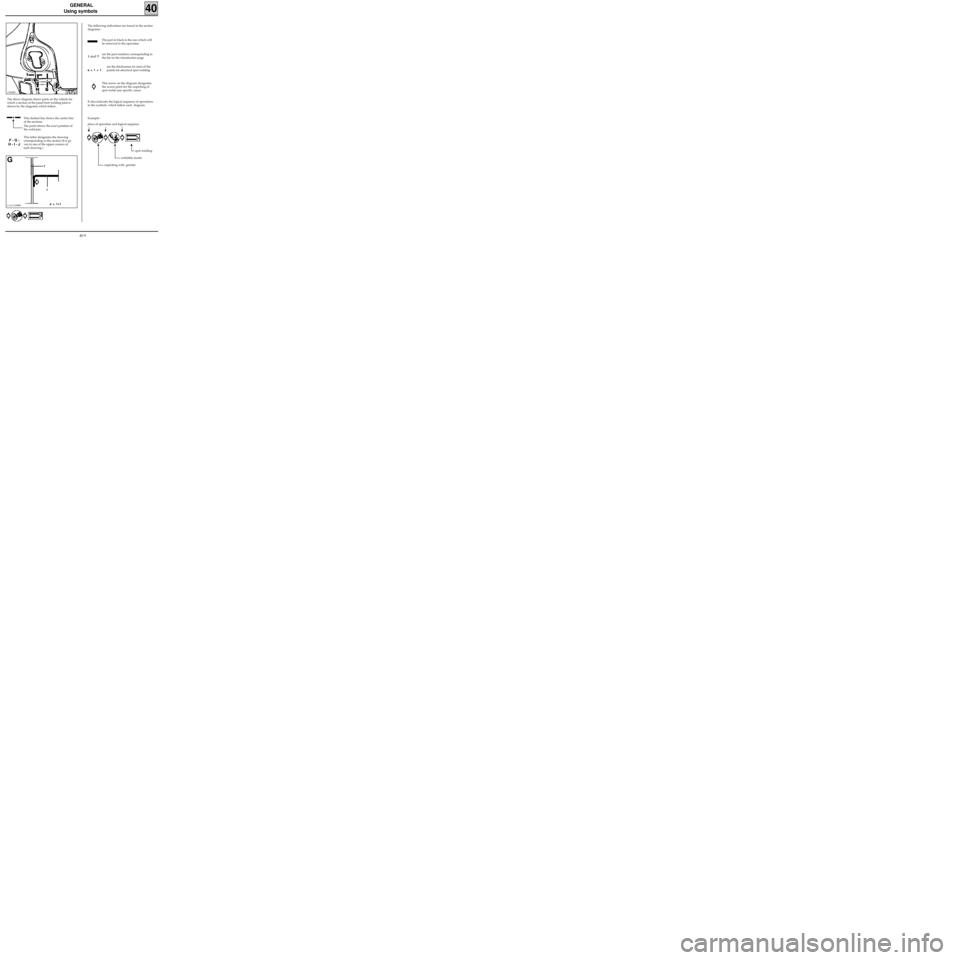
The above diagram shows parts on the vehicle for
which a section of the panel butt welding joint is
shown by the diagrams which follow.
This dashed line shows the centre line
of the sections
The point shows the exact position of
the weld join
This letter designates the drawing
corresponding to the section (It is gi-
ven in one of the upper corners of
each drawing )
F - G -
H - I - J
CAA11538R8
G
1
e = 1+1 7The following indications are found in the section
diagrams :
The part in black is the one which will
be removed in the operation
are the part numbers corresponding to
the list on the introduction page 1
and 7
e = 1 + 1are the thicknesses (in mm) of the
panels for electrical spot welding
This arrow on the diagram designates
the access point for the unpicking of
spot welds (see specific cases)
It also indicates the logical sequence of operations
in the symbols which follow each diagram.
place of operation and logical sequence
spot welding
weldable mastic
unpicking with grinder
Example :
40-9
Page 14 of 255
GENERAL
Using symbols
40
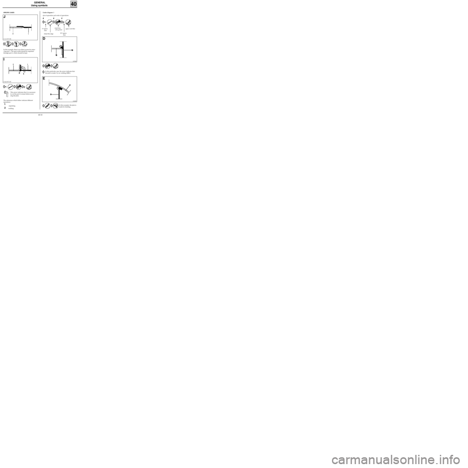
The references which follow indicate different
operations :
unpicking
welding
SPECIFIC CASES
CAA11537-1R6
J
1 2
In this example, there is no direct access for remo-
ving part 1. The spot welds should be unpicked
through part 2, which should be kept.
CAQ11697-1R5
I
1 2
1
2
This arrow indicates that it is necessary
to cut the part it crosses before acces-
sing the joint
.
Under diagram I
1
2
unpicking
with grinderapply weld fillet1st opera-
tion
site of operation and order of operations
10354R
D
In this particular case, the arrow indicates that
the joint is made by arc welding (MIG).
10349R
E
In this example, the joint is
made by bonding.
chisel the edge2nd opera-
tion
1 2
1
2
40-10
Page 47 of 255
LOWER STRUCTURE
Front side member, front section
41B
PRB4122
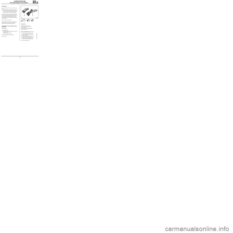
INTRODUCTION
The replacement of this part can be done in two
ways :
A Front side member, complete front section .
B Front side member, partial front section (cut
to be made in front of the front mounting of
the sub-frame), see the following diagram.
In the two cases these are complementary opera-
tions to the replacement of the front end lower
cross member and the headlight carrier panel. As
a result, the joints with these parts will not be
considered here, they will be dealt with in the res-
pective sections.
The repair bench must be used.
The replacement of this part also requires the re-
placement of the side member closure panel
which will have to be ordered separately.
COMPOSITION OF THE PART FROM THE PARTS
DEPARTMENT
1 -Side member
Part assembled with:
- engine mounting height adjuster (only on the
right hand side),
- sub-frame front mounting.
2 - Front side member closure panel
Part on its own.
JOINTS WITH:
Side member closure panel
Front side member, rear section
Front wheel arch
Shock absorber cup height adjuster
Engine mounting *
PARTS CONCERNED (thickness in mm) :
1Front side member, front section 1.5
2Front side member, rear section 2.5
3Front wheel arch 0.8
4Shock absorber cup height adjuster 0.8
5Side member closure panel 1.2
6Engine mounting height adjuster* 1.8
7Engine mounting reinforcement * 1.5
* Only the right hand side.or
41-5
Page 52 of 255
LOWER STRUCTURE
Front side member closure panel
41C
PRB4123
INTRODUCTION
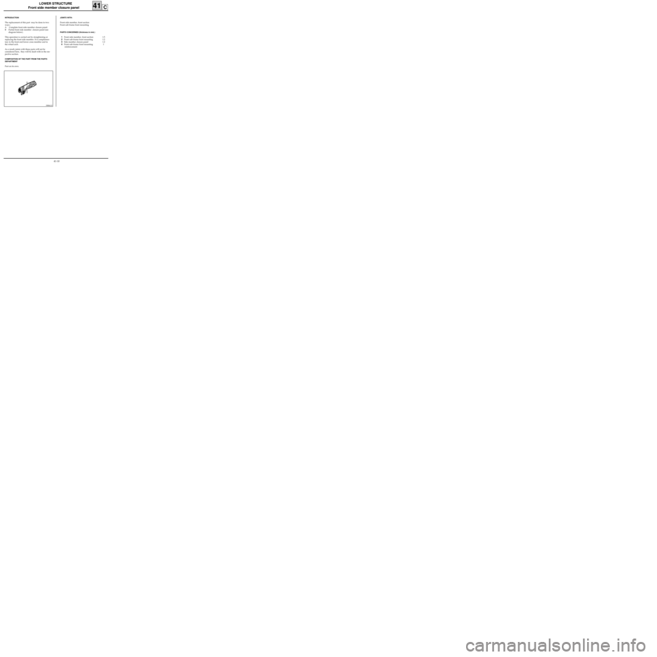
The replacement of this part may be done in two
ways :
A Complete front side member closure panel.
B Partial front side member closure panel (see
diagram below).
This operation is carried out by straightening or
replacing the front side member. It is complemen-
tary to the front end lower cross member and to
the wheel arch.
As a result, joints with these parts will not be
considered here, they will be dealt with in the res-
pective section.
COMPOSITION OF THE PART FROM THE PARTS
DEPARTMENT
Part on its own.
JOINTS WITH:
Front side member, front section
Front sub-frame front mounting
PARTS CONCERNED (thickness in mm) :
1Front side member, front section 1.5
2Front sub-frame front mounting 1.2
3Side member closure panel 1.2
4Front sub-frame front mounting 1
reinforcement
41-10
Page 71 of 255
LOWER STRUCTURE
Sill panel closure panel
41H
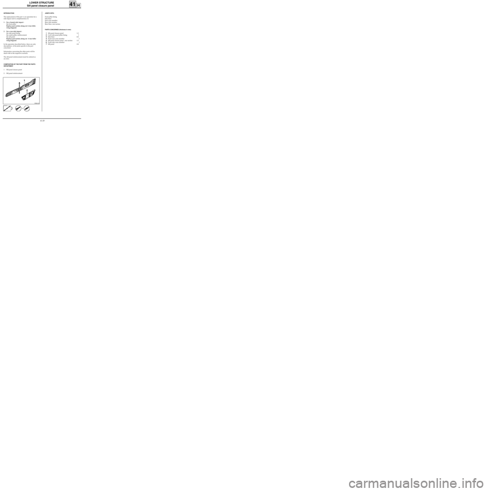
PRB4128
INTRODUCTION
The replacement of this part is an operation for a
side impact and is complementary to:
1 - For a frontal side impact :
the front pillar
Replace part section along cut A (see follo-
wing diagram)
2 - For a rear side impact :
the side panel lining
the centre pillar reinforcement
the sill panel
Replace part section along cut A (see follo-
wing diagram)
In the operation described below, there are only
descriptions of the joints specific to the part
concerned.
Information concerning the other parts will be
dealt with in the respective sections.
The sill panel reinforcement must be ordered as
an extra .
COMPOSITION OF THE PART FROM THE PARTS
DEPARTMENT
1 - Sill panel closure panel
2 - Sill panel reinforcement
JOINTS WITH:
Front pillar lining
Side floor
Seat cross member
Rear side member
Rear floor, rear section
PARTS CONCERNED (thickness in mm):
1Sill panel closure panel 1.2
2Cowl side panel pillar lining 1
3Side floor 0.8
4Front seat cross member 1
5Sill panel closure panel , rear section 1.5
6Front side cross member 1
7Sill panel 0.8
or
41-29
Page 86 of 255
LOWER STRUCTURE
Rear floor, rear section (part section)
41M
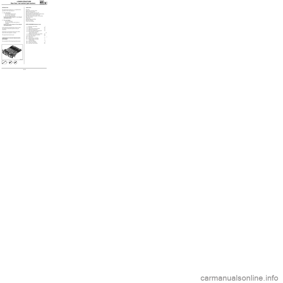
PRB4133
INTRODUCTION
The replacement of this part is a complementary
operation to the replacement of:
1 - For a side impact :
- the sill panel reinforcement ,
- the rear inner wheel arch,
- the rear wing panel lining.
Replace part section along cut A (see diagram
and method below).
2 - For a rear impact
- the rear end panel,
- the rear side member, part section or
complete.
Replace part section along cut B (see diagram
and method below).
In the operation described below, there are only
descriptions of the joints specific to the part
concerned.
Information concerning the other parts will be
dealt with in the respective sections.
The repair bench must be used.
COMPOSITION OF THE PART FROM THE PARTS
DEPARTMENT
Part assembled with towing ring reinforcement.
JOINTS WITH:
Side floor
Upper shock absorber gusset
Sill panel closure panel
Rear axle assembly mounting unit
Shock absorber mounting upper reinforcement
Sill panel closure panel, rear section
Rear floor front cross member, front section
Rear side member
Wheel arch
Spring bumper mounting
Rear floor stiffener
Centre cross member
PARTS CONCERNED (thickness in mm):
1Rear floor, rear section 1
2Side floor 0.8
3Upper shock absorber gusset 1.5
4Sill panel closure panel 1.2
5Rear axle assembly mounting unit 1.2
6Shock absorber mounting
upper reinforcement 1.2
7Sill panel closure panel, rear section 1.5
8Rear floor front cross member 0.8
9Rear side member 1.5
10Wheel arch 1
11Spring bumper mounting 1.5
12Spring bumper mounting
reinforcement 1.5
13Rear floor stiffener 1
14Centre cross member 1.5
15Rear floor, front section 0.8
or
41-44
Page 93 of 255
LOWER STRUCTURE
Rear floor front cross member, front section
41N
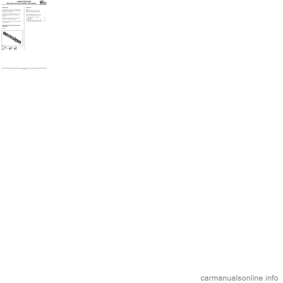
PRB4134
INTRODUCTION
The replacement of this part is a complementary
operation to the replacement of the sill panel clo-
sure panel for a side impact.
In the operation described below, there are only
descriptions of the joints specific to the part
concerned.
Information concerning the other parts will be
dealt with in the respective sections.
This part may be replaced partially (see diagram
and method below).
COMPOSITION OF THE PART FROM THE PARTS
DEPARTMENT
Part only.
JOINTS WITH:
Rear floor
Sill panel closure panel, front section
Sill panel closure panel, rear section
PARTS CONCERNED (thickness in mm):
1Rear floor front cross member,
front section 0.8
2Rear floor 1
3Sill panel closure panel, front section 1.2
4Sill panel closure panel, rear section 1.5
or
41-51
Page 104 of 255
LOWER STRUCTURE
Rear side member, part section
41S
PRB4139
INTRODUCTION
The replacement of this part is a complementary
operation to the replacement of the rear end
cross member for a rear impact
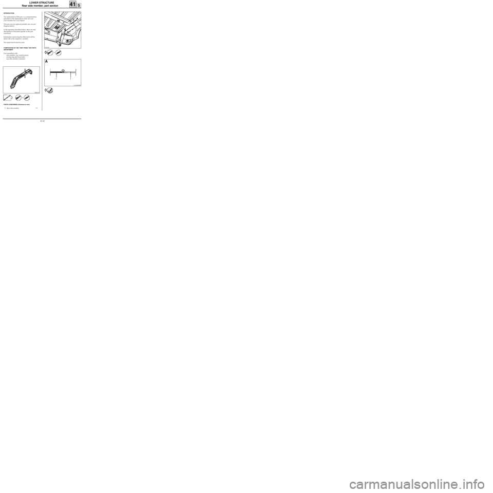
This part may be replaced partially (see cut and
diagram below).
In the operation described below, there are only
descriptions of the joints specific to the part
concerned.
Information concerning the other parts will be
dealt with in the respective sections.
The repair bench must be used.
COMPOSITION OF THE PART FROM THE PARTS
DEPARTMENT
Part assembled with :
- side member rear reinforcement
- towing ring (left hand side),
- rear side member extension .
PARTS CONCERNED (thickness in mm):
1Rear side member 1.5
13221R3
or
CAS13033R1
A
1 1 or
41-62
Page 121 of 255
UPPER FRONT STRUCTURE
Cowl side panel (pillar lining), part section
42C
PRB4210
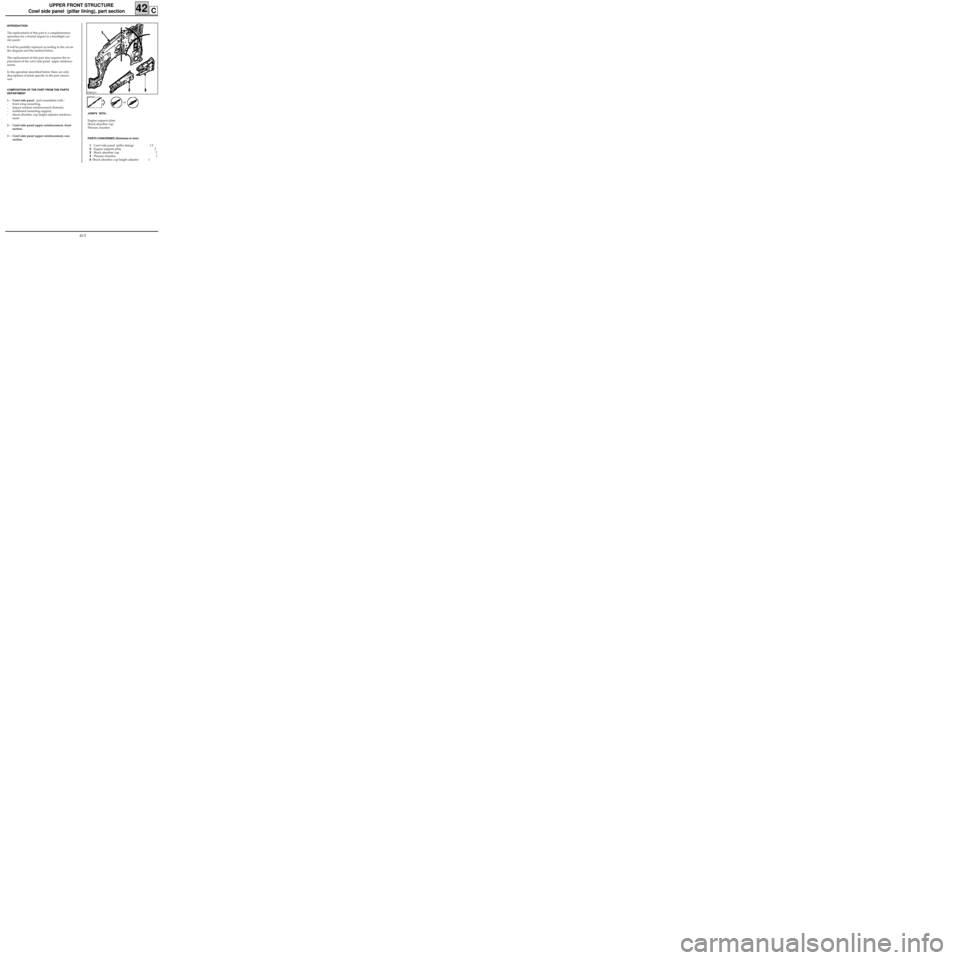
INTRODUCTION
The replacement of this part is a complementary
operation for a frontal impact to a headlight car-
rier panel.
It will be partially replaced according to the cut on
the diagram and the method below.
The replacement of this part also requires the re-
placement of the cowl side panel upper reinforce-
ments.
In the operation described below there are only
descriptions of joints specific to the part concer-
ned.
COMPOSITION OF THE PART FROM THE PARTS
DEPARTMENT
1 - Cowl side panel , part assembled with :
- front wing mounting,
- impact retainer reinforcement (bonnet),
- dashboard mounting support,
- shock absorber cup height adjuster reinforce-
ment .
2 - Cowl side panel upper reinforcement, front
section.
3 - Cowl side panel upper reinforcement, rear
section.
JOINTS WITH :
Engine support plate
Shock absorber cup
Plenum chamber
PARTS CONCERNED (thickness in mm):
1Cowl side panel (pillar lining) 1.5
2Engine support plate 2
3Shock absorber cup 2
4Plenum chamber 1
5 Shock absorber cup height adjuster 1or
42-5
Page 128 of 255
UPPER FRONT STRUCTURE
Wheel arch, front section
42E
PRB4212
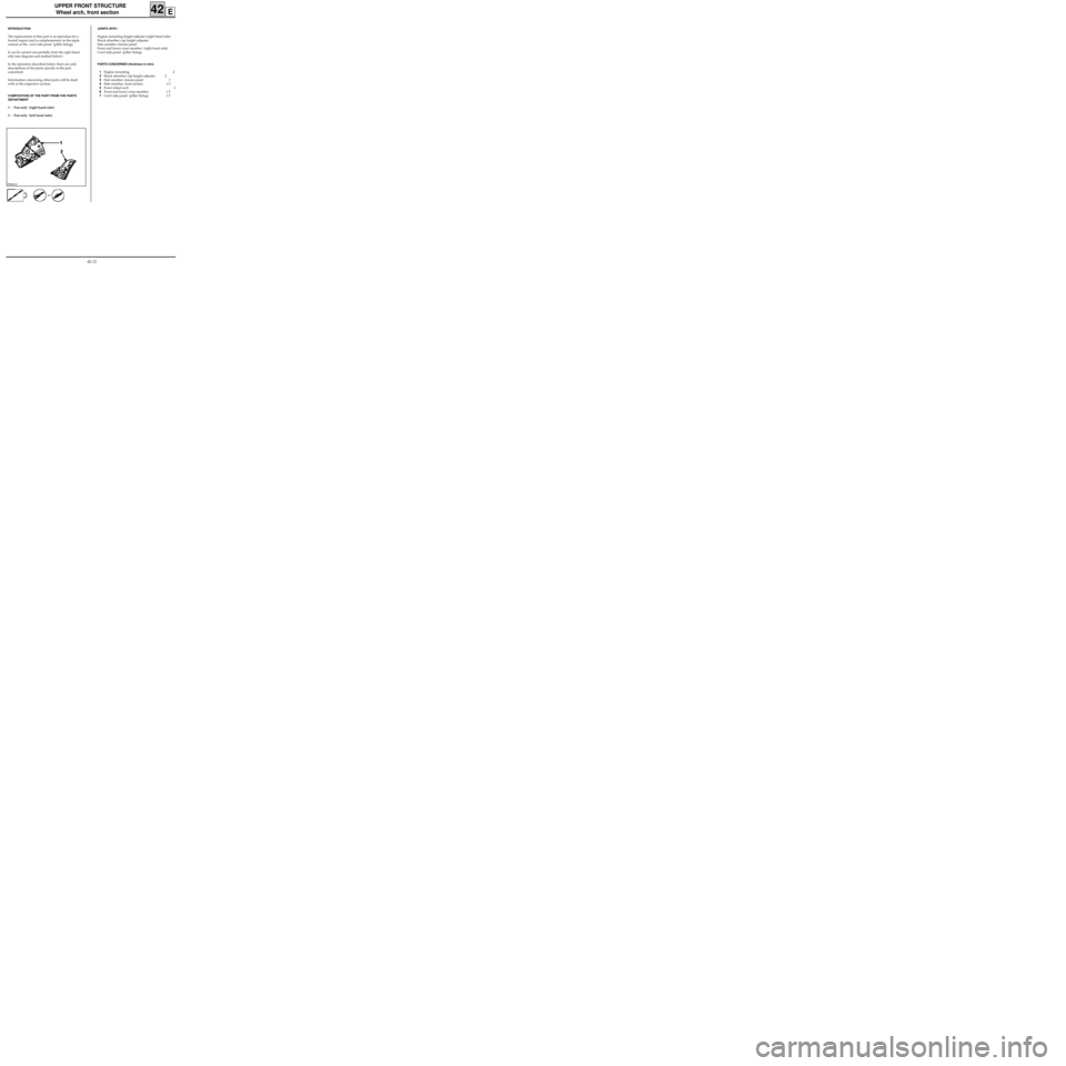
INTRODUCTION
The replacement of this part is an operation for a
frontal impact and is complementary to the repla-
cement of the cowl side panel (pillar lining).
It can be carried out partially from the right hand
side (see diagram and method below).
In the operation described below there are only
descriptions of the joints specific to the part
concerned.
Information concerning other parts will be dealt
with in the respective section.
COMPOSITION OF THE PART FROM THE PARTS
DEPARTMENT
1 - Part only (right hand side).
2 - Part only (left hand side).
JOINTS WITH :
Engine mounting height adjuster (right hand side)
Shock absorber cup height adjuster
Side member closure panel
Front end lower cross member (right hand side)
Cowl side panel (pillar lining)
PARTS CONCERNED (thickness in mm):
1Engine mounting 2
2Shock absorber cup height adjuster 2
3Side member closure panel 1
4Side member, front section 1.5
5Front wheel arch 1
6Front end lower cross member 1.5
7Cowl side panel (pillar lining) 1.5
or
42-12