brake RENAULT KANGOO 2013 X61 / 2.G ABS Bosch 8.1 Workshop Manual
[x] Cancel search | Manufacturer: RENAULT, Model Year: 2013, Model line: KANGOO, Model: RENAULT KANGOO 2013 X61 / 2.GPages: 57, PDF Size: 1.44 MB
Page 3 of 57
38C-3V1 MR-376-X76-38C000$020.mif
38C
ABS BOSCH 8.1
Vdiag No.: 18
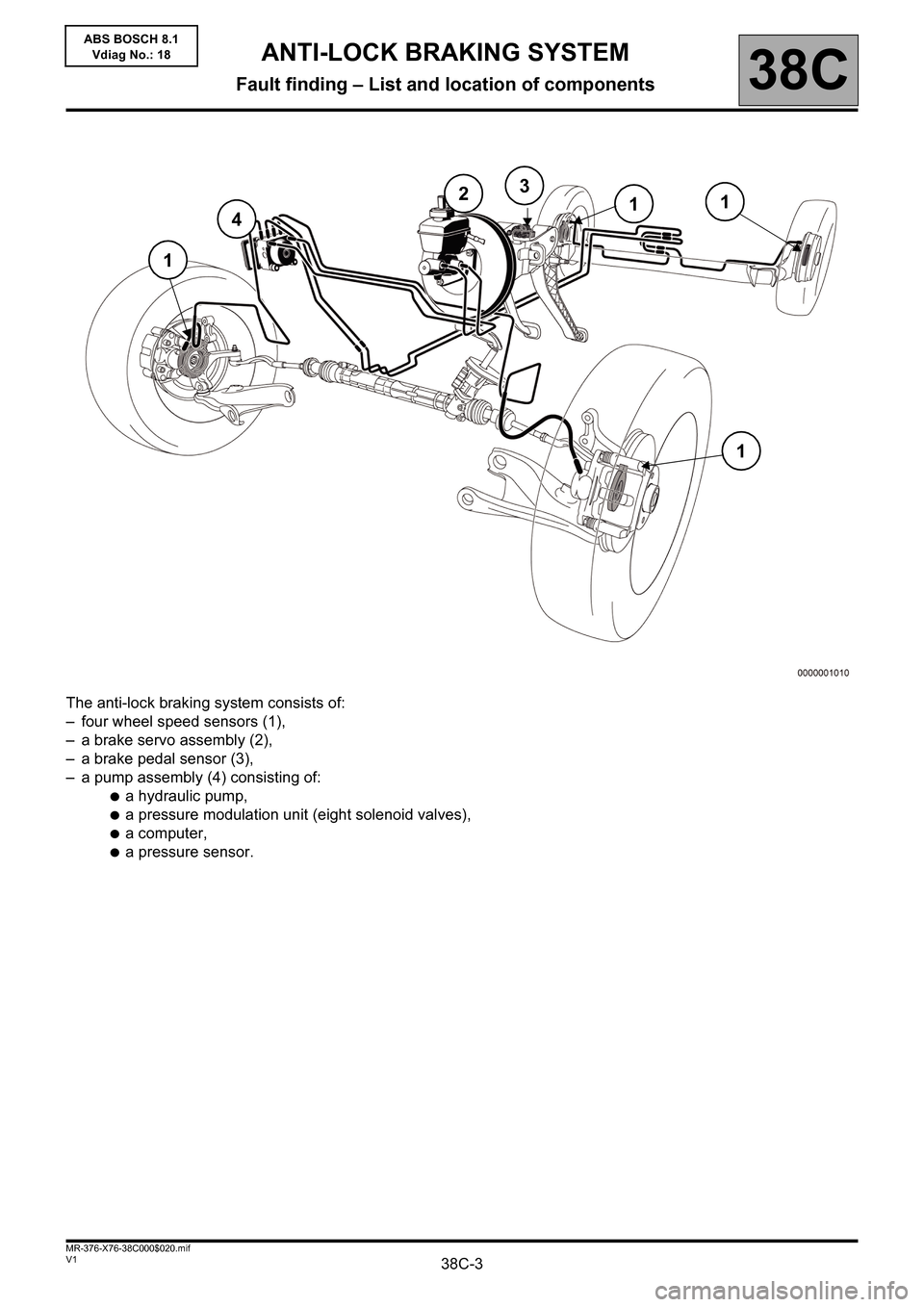
The anti-lock braking system consists of:
– four wheel speed sensors (1),
– a brake servo assembly (2),
– a brake pedal sensor (3),
– a pump assembly (4) consisting of:
●a hydraulic pump,
●a pressure modulation unit (eight solenoid valves),
●a computer,
●a pressure sensor.
1
4
23
11
1
ANTI-LOCK BRAKING SYSTEM
Fault finding – List and location of components
Page 4 of 57
38C-4V1 MR-376-X76-38C000$030.mif
38C
ABS BOSCH 8.1
Vdiag No.: 18
Wheel speed sensor:
Gives the speed of each of the vehicle's wheels.
Analysis of the speeds of the right-hand and left-hand wheel allows the turning direction of the vehicle to be
deduced.
Brake lights switch:
Visual indication of the brake pedal position.
It indicates whether the driver is depressing the brake pedal.
ANTI-LOCK BRAKING SYSTEM
Fault finding – Role of components
Page 6 of 57
38C-6V1 MR-376-X76-38C000$040.mif
ANTI-LOCK BRAKING SYSTEM
Fault finding – Operating diagram38C
ABS BOSCH 8.1
Vdiag No.: 18
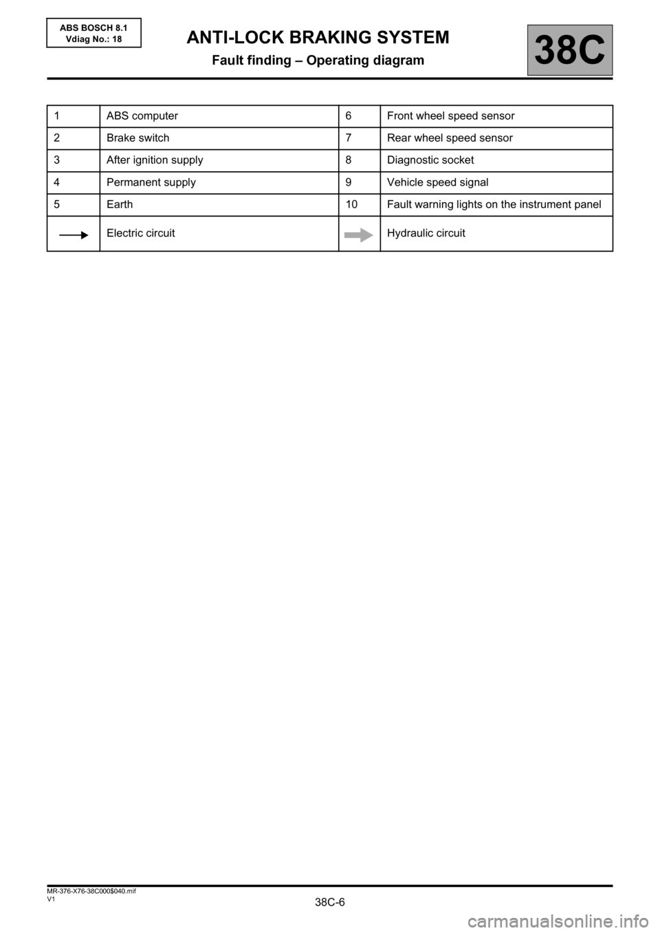
1 ABS computer 6 Front wheel speed sensor
2 Brake switch 7 Rear wheel speed sensor
3 After ignition supply 8 Diagnostic socket
4 Permanent supply 9 Vehicle speed signal
5 Earth 10 Fault warning lights on the instrument panel
Electric circuit Hydraulic circuit
Page 7 of 57
38C-7V1 MR-376-X76-38C000$050.mif
38C
ABS BOSCH 8.1
Vdiag No.: 18
On this vehicle, the main functions of the ABS are as follows:
● electronic distribution of braking between front and rear by controlling skidding of the rear wheels,
● keeping the wheels from locking by controlling skidding of the four wheels.
The ABS prevents the wheels from locking when braking. This function allows the vehicle to be steered under
braking and ensures vehicle stability under braking.
EBD (electronic braking distribution):
The electronic braking distribution unit optimises the brakeforce distribution between the front and rear axles. This
function ensures vehicle stability under braking.
Fault finding warning lights programming
Instrument panel warning light Meaning
- ABS ABS function inoperative.
Brake faults ABSElectronic braking regulation and ABS
function not working
Brake faults
flashing at 2HzABS flashing at 2HzABS computer is in fault finding mode.
- ABS flashing at 8HzTachometer index or vehicle
configuration not programmed.
ANTI-LOCK BRAKING SYSTEM
Fault finding – System operation
Page 29 of 57
38C-29V1 MR-376-X76-38C000$100.mif
38C
ABS BOSCH 8.1
Vdiag No.: 18
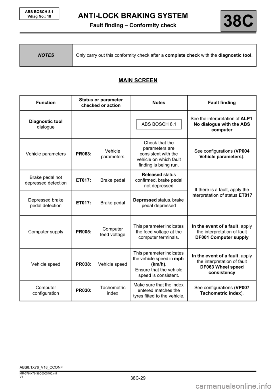
MAIN SCREEN
NOTESOnly carry out this conformity check after a complete check with the diagnostic tool.
FunctionStatus or parameter
checked or actionNotes Fault finding
Diagnostic tool
dialogueSee the interpretation of ALP1
No dialogue with the ABS
computer ABS BOSCH 8.1
Vehicle parametersPR063:Vehicle
parametersCheck that the
parameters are
consistent with the
vehicle on which fault
finding is being run.See configurations (VP004
Vehicle parameters).
Brake pedal not
depressed detectionET017:Brake pedalReleased status
confirmed, brake pedal
not depressed
If there is a fault, apply the
interpretation of status ET017
Depressed brake
pedal detectionET017:Brake pedalDepressed status, brake
pedal depressed
Computer supplyPR005:Computer
feed voltageThis parameter indicates
the feed voltage at the
computer terminals.In the event of a fault, apply
the interpretation of fault
DF001 Computer supply
Vehicle speedPR038:Vehicle speedThis parameter indicates
the vehicle speed in mph
(km/h).
Ensure that the vehicle
speed is consistent.In the event of a fault, apply
the interpretation of fault
DF063 Wheel speed
consistency
Computer
configurationPR030:Tachometric
indexMake sure that the index
entered matches the
tyres fitted to the vehicle.See configurations (VP007
Tachometric index).
ABS8.1X76_V18_CCONF
ANTI-LOCK BRAKING SYSTEM
Fault finding – Conformity check
Page 32 of 57
38C-32V1 MR-376-X76-38C000$110.mif
38C
ABS BOSCH 8.1
Vdiag No.: 18
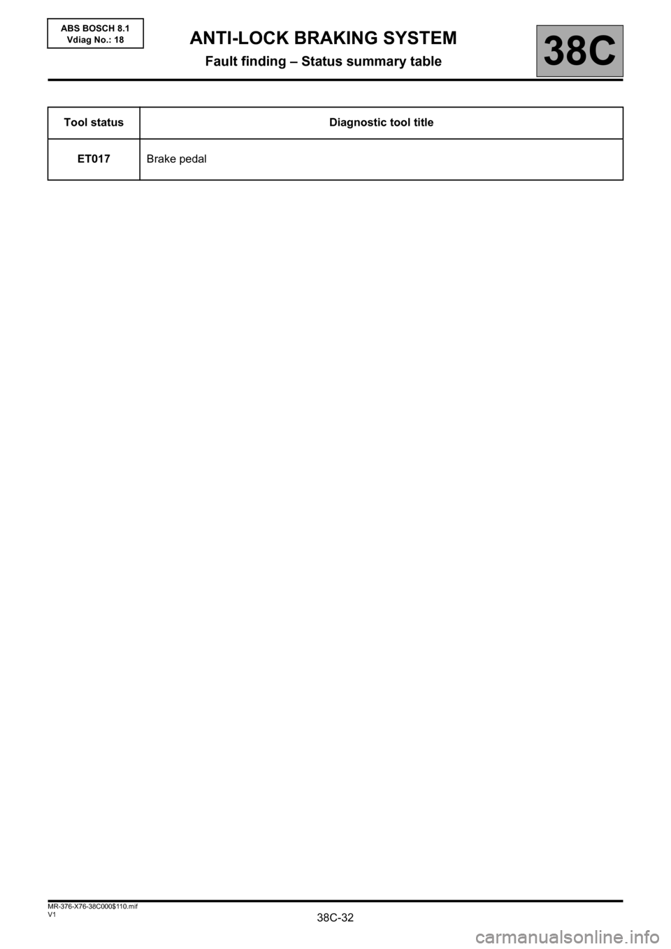
Tool status Diagnostic tool title
ET017Brake pedal
ANTI-LOCK BRAKING SYSTEM
Fault finding – Status summary table
Page 33 of 57
38C-33
AFTER REPAIRClear the computer memory using command RZ001 Fault memory.
Carry out a road test followed by another check with the diagnostic tool.
V1 MR-376-X76-38C000$120.mif
38C
ABS BOSCH 8.1
Vdiag No.: 18
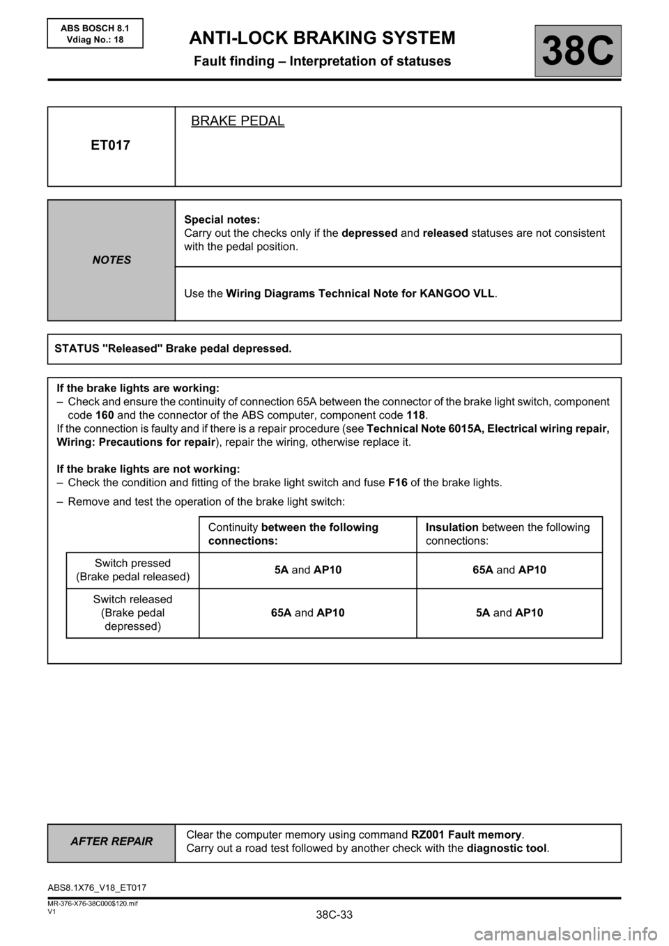
ET017BRAKE PEDAL
NOTESSpecial notes:
Carry out the checks only if the depressed and released statuses are not consistent
with the pedal position.
Use the Wiring Diagrams Technical Note for KANGOO VLL.
STATUS "Released" Brake pedal depressed.
If the brake lights are working:
– Check and ensure the continuity of connection 65A between the connector of the brake light switch, component
code 160 and the connector of the ABS computer, component code 118.
If the connection is faulty and if there is a repair procedure (see Technical Note 6015A, Electrical wiring repair,
Wiring: Precautions for repair), repair the wiring, otherwise replace it.
If the brake lights are not working:
– Check the condition and fitting of the brake light switch and fuse F16 of the brake lights.
– Remove and test the operation of the brake light switch:
Continuity between the following
connections:Insulation between the following
connections:
Switch pressed
(Brake pedal released)5A and AP10 65A and AP10
Switch released
(Brake pedal
depressed)65A and AP10 5A and AP10
ABS8.1X76_V18_ET017
ANTI-LOCK BRAKING SYSTEM
Fault finding – Interpretation of statuses
Page 34 of 57
38C-34
AFTER REPAIRClear the computer memory using command RZ001 Fault memory.
Carry out a road test followed by another check with the diagnostic tool.
V1 MR-376-X76-38C000$120.mif
ANTI-LOCK BRAKING SYSTEM
Fault finding – Interpretation of statuses38C
ABS BOSCH 8.1
Vdiag No.: 18
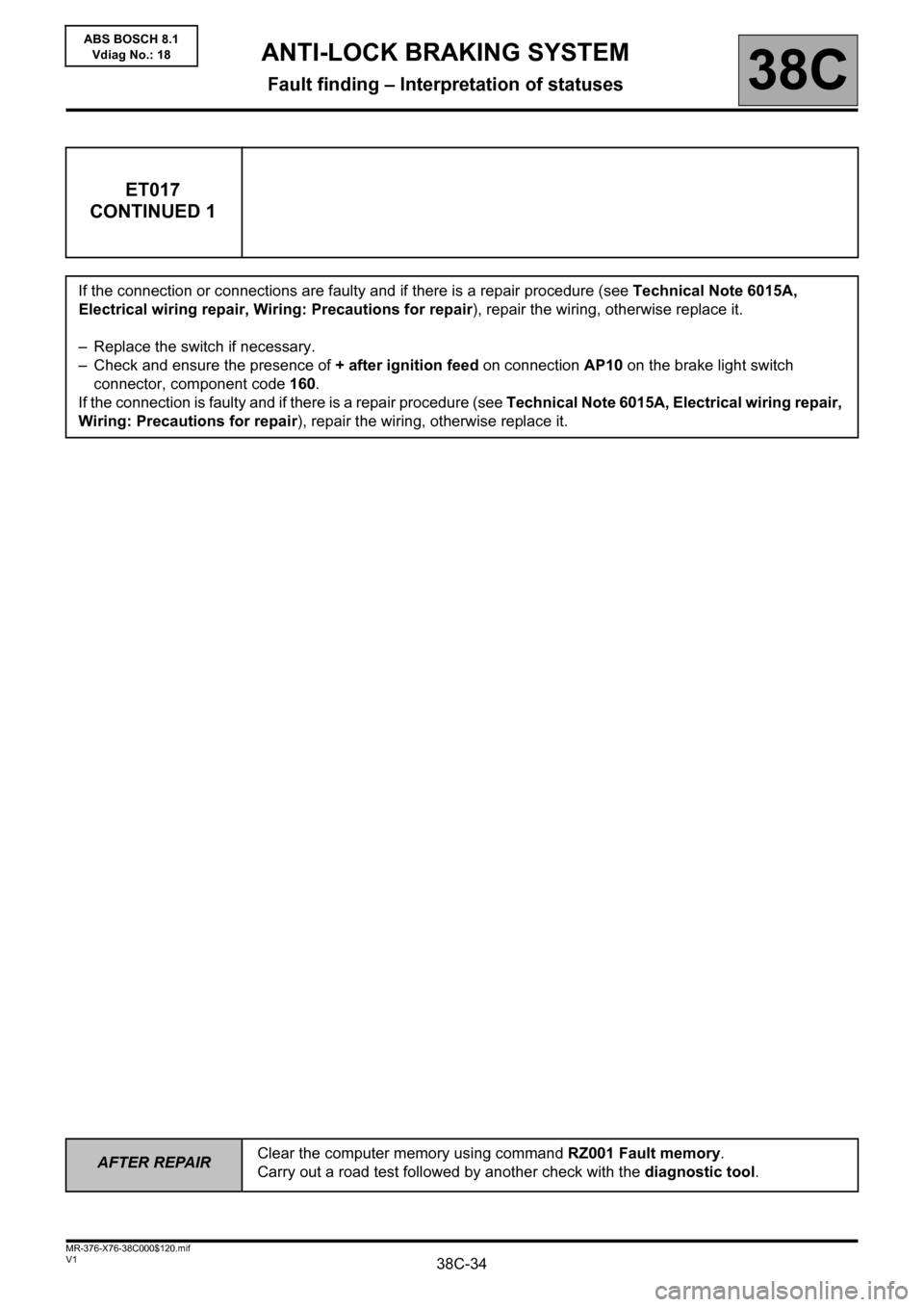
ET017
CONTINUED 1
If the connection or connections are faulty and if there is a repair procedure (see Technical Note 6015A,
Electrical wiring repair, Wiring: Precautions for repair), repair the wiring, otherwise replace it.
– Replace the switch if necessary.
– Check and ensure the presence of + after ignition feed on connection AP10 on the brake light switch
connector, component code 160.
If the connection is faulty and if there is a repair procedure (see Technical Note 6015A, Electrical wiring repair,
Wiring: Precautions for repair), repair the wiring, otherwise replace it.
Page 35 of 57
38C-35
AFTER REPAIRClear the computer memory using command RZ001 Fault memory.
Carry out a road test followed by another check with the diagnostic tool.
V1 MR-376-X76-38C000$120.mif
ANTI-LOCK BRAKING SYSTEM
Fault finding – Interpretation of statuses38C
ABS BOSCH 8.1
Vdiag No.: 18
ET017
CONTINUED 2
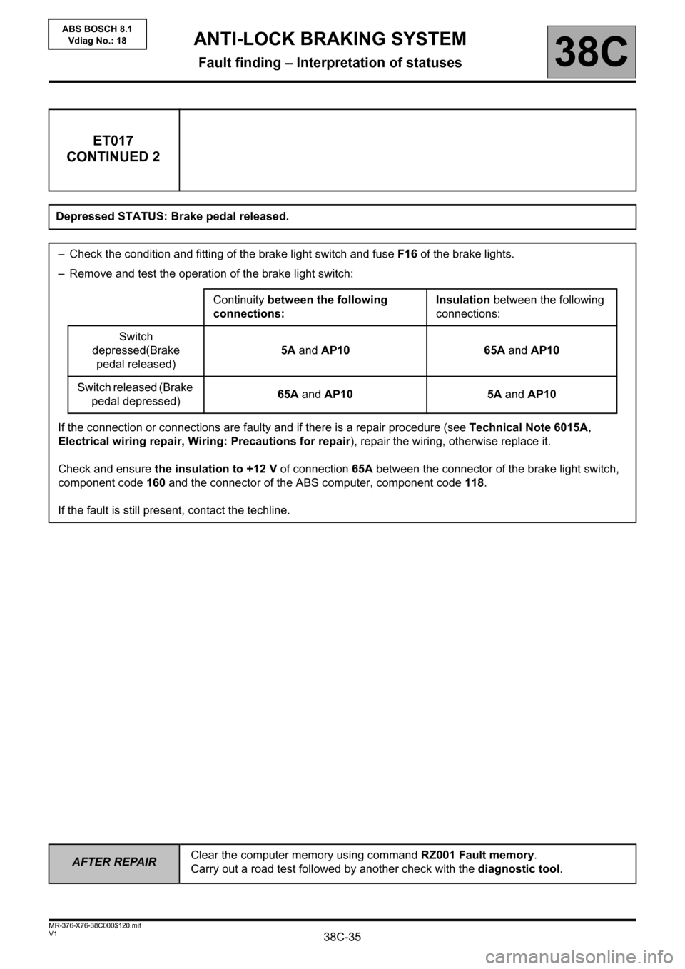
Depressed STATUS: Brake pedal released.
– Check the condition and fitting of the brake light switch and fuse F16 of the brake lights.
– Remove and test the operation of the brake light switch:
Continuity between the following
connections:Insulation between the following
connections:
Switch
depressed(Brake
pedal released)5A and AP10 65A and AP10
Switch released (Brake
pedal depressed)65A and AP10 5A and AP10
If the connection or connections are faulty and if there is a repair procedure (see Technical Note 6015A,
Electrical wiring repair, Wiring: Precautions for repair), repair the wiring, otherwise replace it.
Check and ensure the insulation to +12 V of connection 65A between the connector of the brake light switch,
component code 160 and the connector of the ABS computer, component code 118.
If the fault is still present, contact the techline.
Page 38 of 57
38C-38V1 MR-376-X76-38C000$140.mif
ANTI-LOCK BRAKING SYSTEM
Fault finding – Command summary table38C
ABS BOSCH 8.1
Vdiag No.: 18
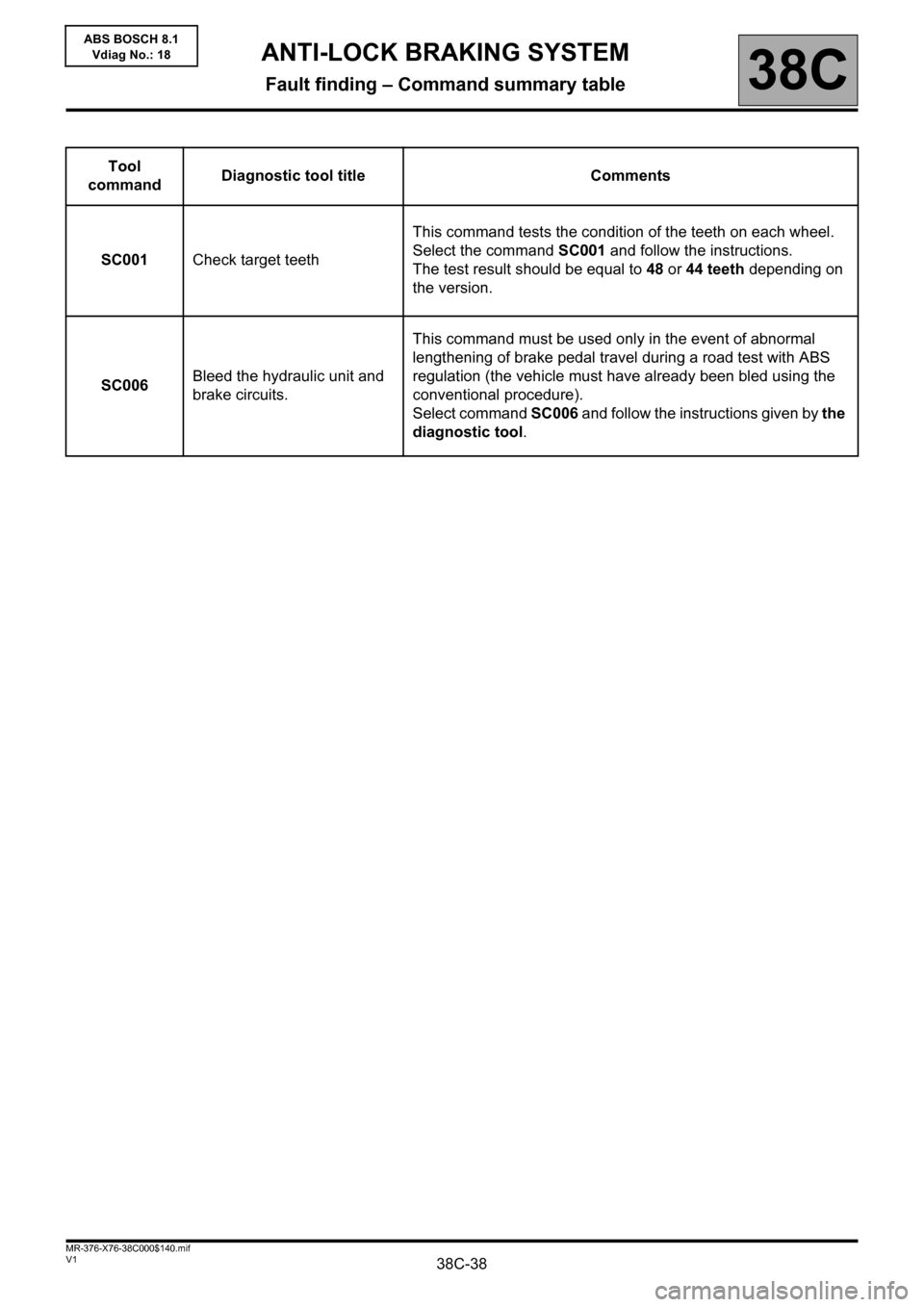
Tool
commandDiagnostic tool title Comments
SC001Check target teethThis command tests the condition of the teeth on each wheel.
Select the command SC001 and follow the instructions.
The test result should be equal to 48 or 44 teeth depending on
the version.
SC006Bleed the hydraulic unit and
brake circuits.This command must be used only in the event of abnormal
lengthening of brake pedal travel during a road test with ABS
regulation (the vehicle must have already been bled using the
conventional procedure).
Select command SC006 and follow the instructions given by the
diagnostic tool.