RENAULT KANGOO 2013 X61 / 2.G Air Bags AC4 And Pretensioners Owner's Manual
Manufacturer: RENAULT, Model Year: 2013, Model line: KANGOO, Model: RENAULT KANGOO 2013 X61 / 2.GPages: 40, PDF Size: 0.55 MB
Page 21 of 40
88C-21
AFTER REPAIRDeal with any faults displayed by the diagnostic tool.
Clear the computer memory.
Carry out a road test followed by another check with the diagnostic tool.
V1 MR-376-X76-88C000$060.mif
AIRBAGS AND PRETENSIONERS
Fault finding – Interpretation of faults88C
2nd generation
(AC4 phase II)
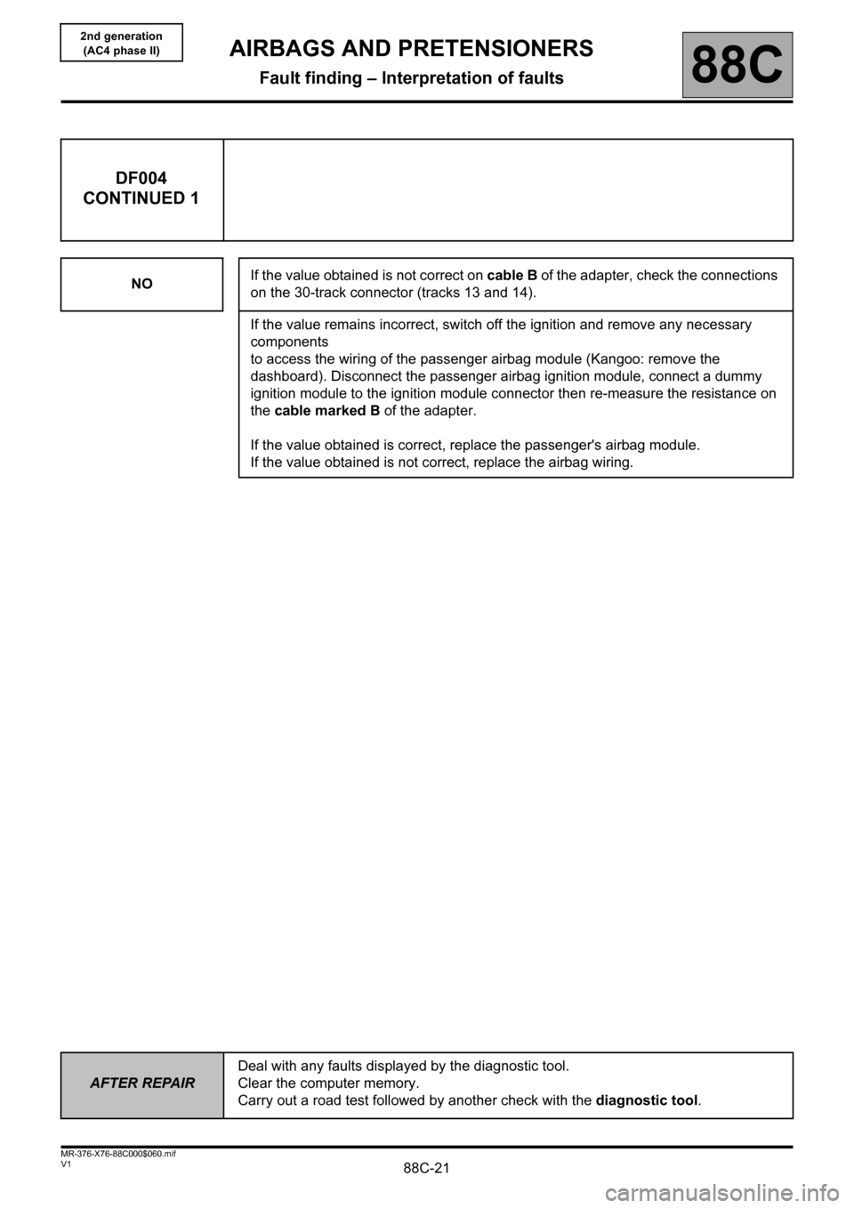
DF004
CONTINUED 1
NOIf the value obtained is not correct on cable B of the adapter, check the connections
on the 30-track connector (tracks 13 and 14).
If the value remains incorrect, switch off the ignition and remove any necessary
components
to access the wiring of the passenger airbag module (Kangoo: remove the
dashboard). Disconnect the passenger airbag ignition module, connect a dummy
ignition module to the ignition module connector then re-measure the resistance on
the cable marked B of the adapter.
If the value obtained is correct, replace the passenger's airbag module.
If the value obtained is not correct, replace the airbag wiring.
Page 22 of 40

88C-22
AFTER REPAIRDeal with any faults displayed by the diagnostic tool.
Clear the computer memory.
Carry out a road test followed by another check with the diagnostic tool.
V1 MR-376-X76-88C000$060.mif
AIRBAGS AND PRETENSIONERS
Fault finding – Interpretation of faults88C
2nd generation
(AC4 phase II)
DF004
CONTINUED 2
CC.1 - CC.0NOTESNone.
Lock the computer.
Switch off the ignition, disconnect the computer connector and fit the B40 30-track adapter.
The CLIP, NXR or XRBAG tools must be used for measuring the insulation appropriate to the type of fault on the
cable marked B on the adapter.
Is the value obtained correct?
YESIf the value obtained is correct on cable B of the adapter, check the condition of the
connections on the computer.
NOIf the value obtained is not correct on cable B of the adapter, check the connections
on the 30-track connector (tracks 13/14).
If the value remains incorrect, replace the airbag wiring.
Page 23 of 40
88C-23
AFTER REPAIRDeal with any faults displayed by the diagnostic tool.
Clear the computer memory.
Carry out a road test followed by another check with the diagnostic tool.
V1 MR-376-X76-88C000$060.mif
AIRBAGS AND PRETENSIONERS
Fault finding – Interpretation of faults88C
2nd generation
(AC4 phase II)
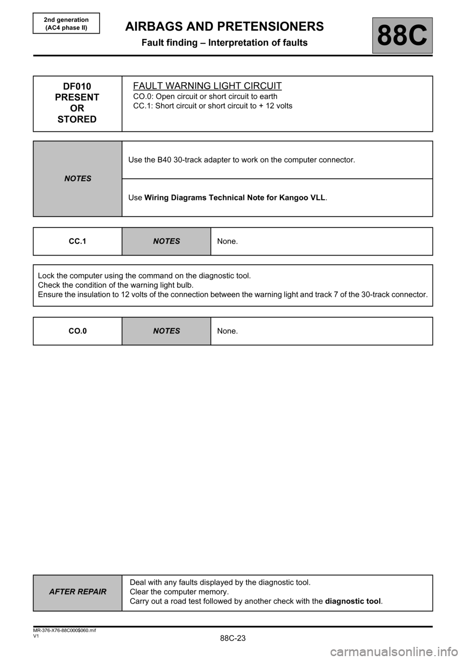
DF010
PRESENT
OR
STOREDFAULT WARNING LIGHT CIRCUIT
CO.0: Open circuit or short circuit to earth
CC.1: Short circuit or short circuit to + 12 volts
NOTESUse the B40 30-track adapter to work on the computer connector.
Use Wiring Diagrams Technical Note for Kangoo VLL.
CC.1
NOTESNone.
Lock the computer using the command on the diagnostic tool.
Check the condition of the warning light bulb.
Ensure the insulation to 12 volts of the connection between the warning light and track 7 of the 30-track connector.
CO.0
NOTESNone.
Page 24 of 40
88C-24
AFTER REPAIRDeal with any faults displayed by the diagnostic tool.
Clear the computer memory.
Carry out a road test followed by another check with the diagnostic tool.
V1 MR-376-X76-88C000$060.mif
AIRBAGS AND PRETENSIONERS
Fault finding – Interpretation of faults88C
2nd generation
(AC4 phase II)
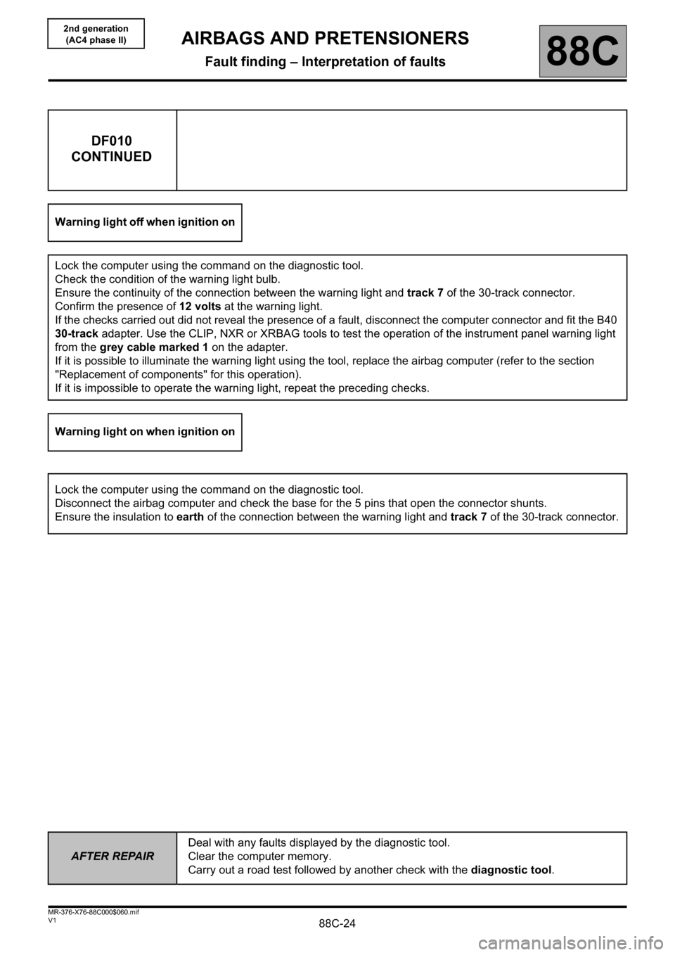
DF010
CONTINUED
Warning light off when ignition on
Lock the computer using the command on the diagnostic tool.
Check the condition of the warning light bulb.
Ensure the continuity of the connection between the warning light and track 7 of the 30-track connector.
Confirm the presence of 12 volts at the warning light.
If the checks carried out did not reveal the presence of a fault, disconnect the computer connector and fit the B40
30-track adapter. Use the CLIP, NXR or XRBAG tools to test the operation of the instrument panel warning light
from the grey cable marked 1 on the adapter.
If it is possible to illuminate the warning light using the tool, replace the airbag computer (refer to the section
"Replacement of components" for this operation).
If it is impossible to operate the warning light, repeat the preceding checks.
Warning light on when ignition on
Lock the computer using the command on the diagnostic tool.
Disconnect the airbag computer and check the base for the 5 pins that open the connector shunts.
Ensure the insulation to earth of the connection between the warning light and track 7 of the 30-track connector.
Page 25 of 40

88C-25
AFTER REPAIRDeal with any faults displayed by the diagnostic tool.
Clear the computer memory.
Carry out a road test followed by another check with the diagnostic tool.
V1 MR-376-X76-88C000$060.mif
AIRBAGS AND PRETENSIONERS
Fault finding – Interpretation of faults88C
2nd generation
(AC4 phase II)
DF016
PRESENTCOMPUTER CONFIGURATION
NOTESThis fault may appear after using the passenger airbag locking command, by not
observing the procedure described in the Technical Note (this command allows a child
seat to be fitted on the passenger seat).
It is vital that you never use this passenger airbag locking command before a
Technical Note dealing with the subject has been distributed.
This fault corresponds to an inconsistency between the computer configuration and the vehicle equipment
detected by the computer. The computer has detected the presence of a component additional to its configuration.
Modify the computer configuration using the Configuration command on the diagnostic tools.
Page 26 of 40
88C-26
AFTER REPAIRDeal with any faults displayed by the diagnostic tool.
Clear the computer memory.
Carry out a road test followed by another check with the diagnostic tool.
V1 MR-376-X76-88C000$060.mif
AIRBAGS AND PRETENSIONERS
Fault finding – Interpretation of faults88C
2nd generation
(AC4 phase II)
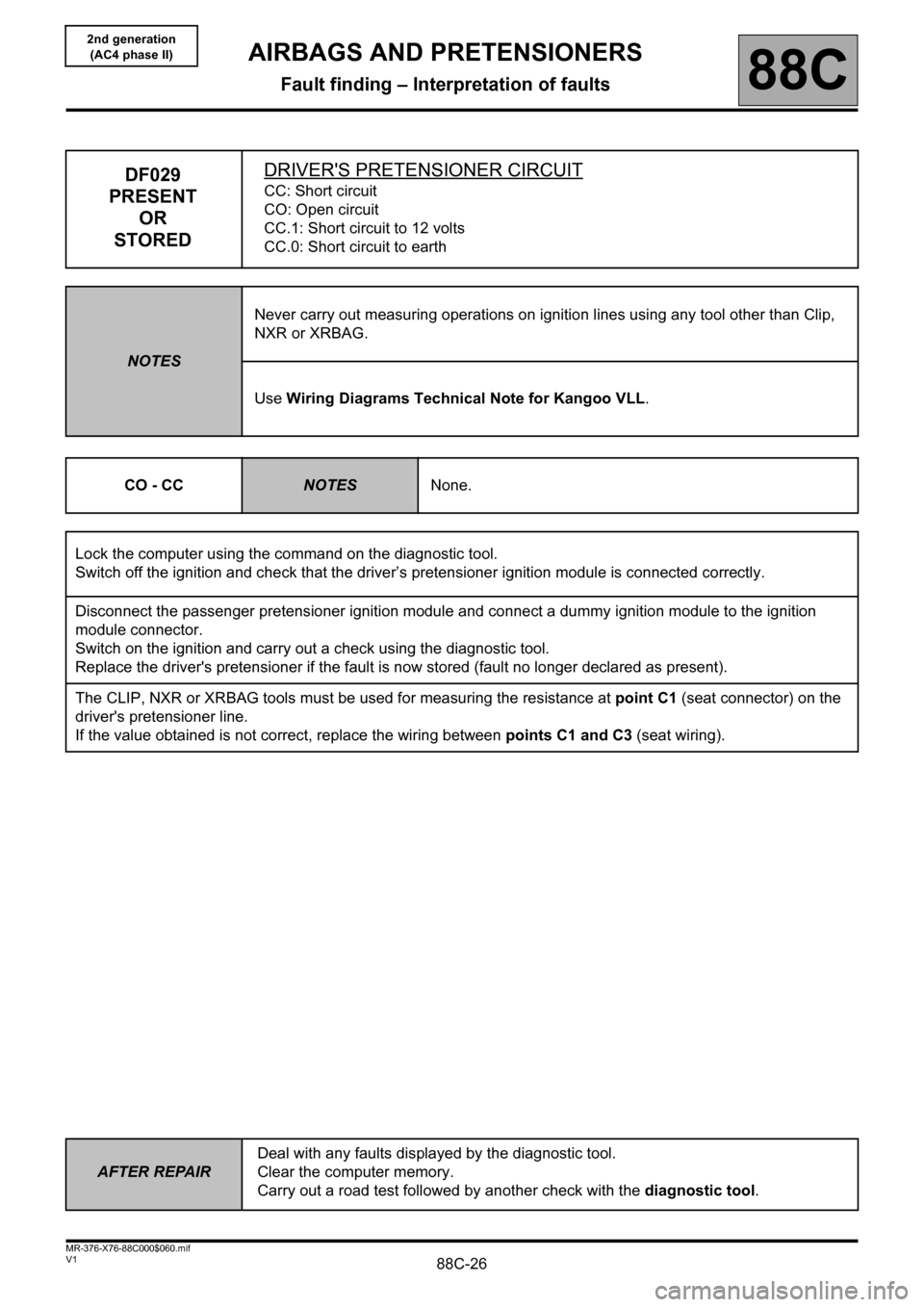
DF029
PRESENT
OR
STOREDDRIVER'S PRETENSIONER CIRCUITCC: Short circuit
CO: Open circuit
CC.1: Short circuit to 12 volts
CC.0: Short circuit to earth
NOTESNever carry out measuring operations on ignition lines using any tool other than Clip,
NXR or XRBAG.
Use Wiring Diagrams Technical Note for Kangoo VLL.
CO - CC
NOTESNone.
Lock the computer using the command on the diagnostic tool.
Switch off the ignition and check that the driver’s pretensioner ignition module is connected correctly.
Disconnect the passenger pretensioner ignition module and connect a dummy ignition module to the ignition
module connector.
Switch on the ignition and carry out a check using the diagnostic tool.
Replace the driver's pretensioner if the fault is now stored (fault no longer declared as present).
The CLIP, NXR or XRBAG tools must be used for measuring the resistance at point C1 (seat connector) on the
driver's pretensioner line.
If the value obtained is not correct, replace the wiring between points C1 and C3 (seat wiring).
Page 27 of 40
88C-27
AFTER REPAIRDeal with any faults displayed by the diagnostic tool.
Clear the computer memory.
Carry out a road test followed by another check with the diagnostic tool.
V1 MR-376-X76-88C000$060.mif
AIRBAGS AND PRETENSIONERS
Fault finding – Interpretation of faults88C
2nd generation
(AC4 phase II)
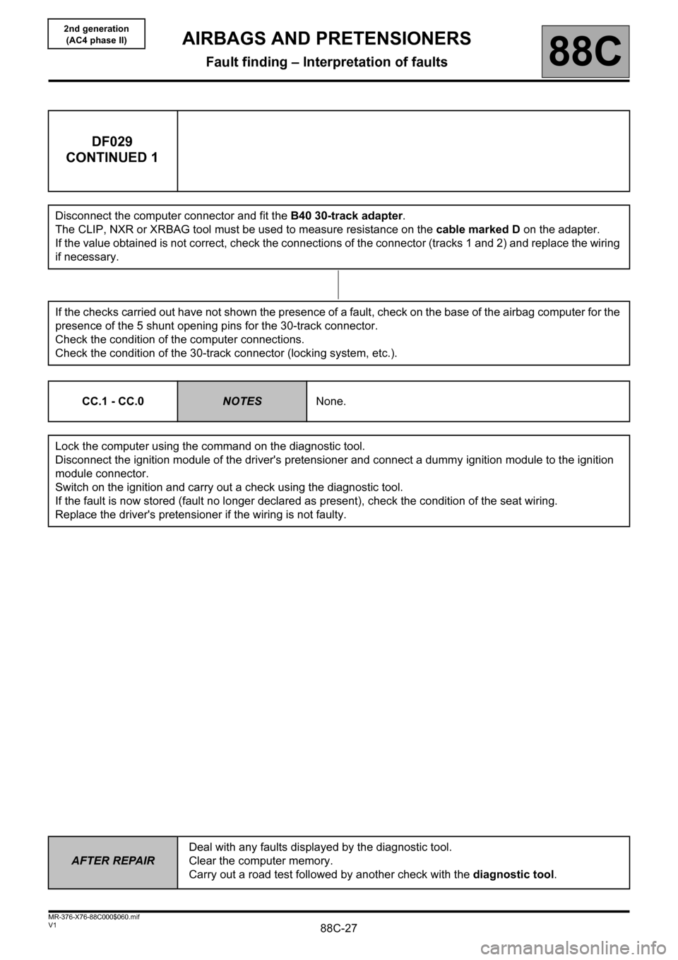
DF029
CONTINUED 1
Disconnect the computer connector and fit the B40 30-track adapter.
The CLIP, NXR or XRBAG tool must be used to measure resistance on the cable marked D on the adapter.
If the value obtained is not correct, check the connections of the connector (tracks 1 and 2) and replace the wiring
if necessary.
If the checks carried out have not shown the presence of a fault, check on the base of the airbag computer for the
presence of the 5 shunt opening pins for the 30-track connector.
Check the condition of the computer connections.
Check the condition of the 30-track connector (locking system, etc.).
CC.1 - CC.0
NOTESNone.
Lock the computer using the command on the diagnostic tool.
Disconnect the ignition module of the driver's pretensioner and connect a dummy ignition module to the ignition
module connector.
Switch on the ignition and carry out a check using the diagnostic tool.
If the fault is now stored (fault no longer declared as present), check the condition of the seat wiring.
Replace the driver's pretensioner if the wiring is not faulty.
Page 28 of 40

88C-28
AFTER REPAIRDeal with any faults displayed by the diagnostic tool.
Clear the computer memory.
Carry out a road test followed by another check with the diagnostic tool.
V1 MR-376-X76-88C000$060.mif
AIRBAGS AND PRETENSIONERS
Fault finding – Interpretation of faults88C
2nd generation
(AC4 phase II)
DF029
CONTINUED 2
The CLIP, NXR or XRBAG tool must be used for measuring the insulation appropriate to the type of fault at point
C1 (seat connector) of the driver's pretensioner line.
If the value obtained is not correct, replace the wiring between points C1 and C3 (seat wiring).
Disconnect the computer connector and fit the B40 30-track adapter.
The CLIP, NXR or XRBAG tools must be used for measuring the insulation appropriate to the type of fault on the
cable marked D on the adapter.
If the value obtained is not correct, check the connections of the connector (tracks 1 and 2) and replace the wiring
if necessary.
If the checks carried out have not shown the presence of a fault on the driver's pretensioner circuit, check on the
base of the airbag computer for the presence of the 5 shunt opening pins for the 30-track connector.
Check the condition of the computer connections.
Check the condition of the 30-track connector (locking system, etc.).
Page 29 of 40
88C-29
AFTER REPAIRDeal with any faults displayed by the diagnostic tool.
Clear the computer memory.
Carry out a road test followed by another check with the diagnostic tool.
V1 MR-376-X76-88C000$060.mif
AIRBAGS AND PRETENSIONERS
Fault finding – Interpretation of faults88C
2nd generation
(AC4 phase II)
DF030
PRESENT
OR
STOREDPASSENGER'S PRETENSIONER CIRCUITCC: Short circuit
CO: Open circuit
CC.1: Short circuit to 12 volts
CC.0: Short circuit to earth
NOTESNever carry out measuring operations on ignition lines using any tool other than Clip,
NXR or XRBAG.
Use Wiring Diagrams Technical Note for Kangoo VLL.
CO - CC
NOTESNone.
Lock the computer using the command on the diagnostic tool.
Switch off the ignition and check that the passenger pretensioner ignition module is connected correctly.
Disconnect the passenger pretensioner ignition module and connect a dummy ignition module to the ignition
module connector.
Switch on the ignition and carry out a check using the diagnostic tool.
Replace the passenger's pretensioner if the fault has been stored (fault no longer indicated).
The CLIP, NXR or XRBAG tools must be used for measuring the resistance at point C1 (seat connector) on the
passenger pretensioner line.
If the value obtained is not correct, replace the wiring between points C1 and C3 (seat wiring).
Page 30 of 40
88C-30
AFTER REPAIRDeal with any faults displayed by the diagnostic tool.
Clear the computer memory.
Carry out a road test followed by another check with the diagnostic tool.
V1 MR-376-X76-88C000$060.mif
AIRBAGS AND PRETENSIONERS
Fault finding – Interpretation of faults88C
2nd generation
(AC4 phase II)
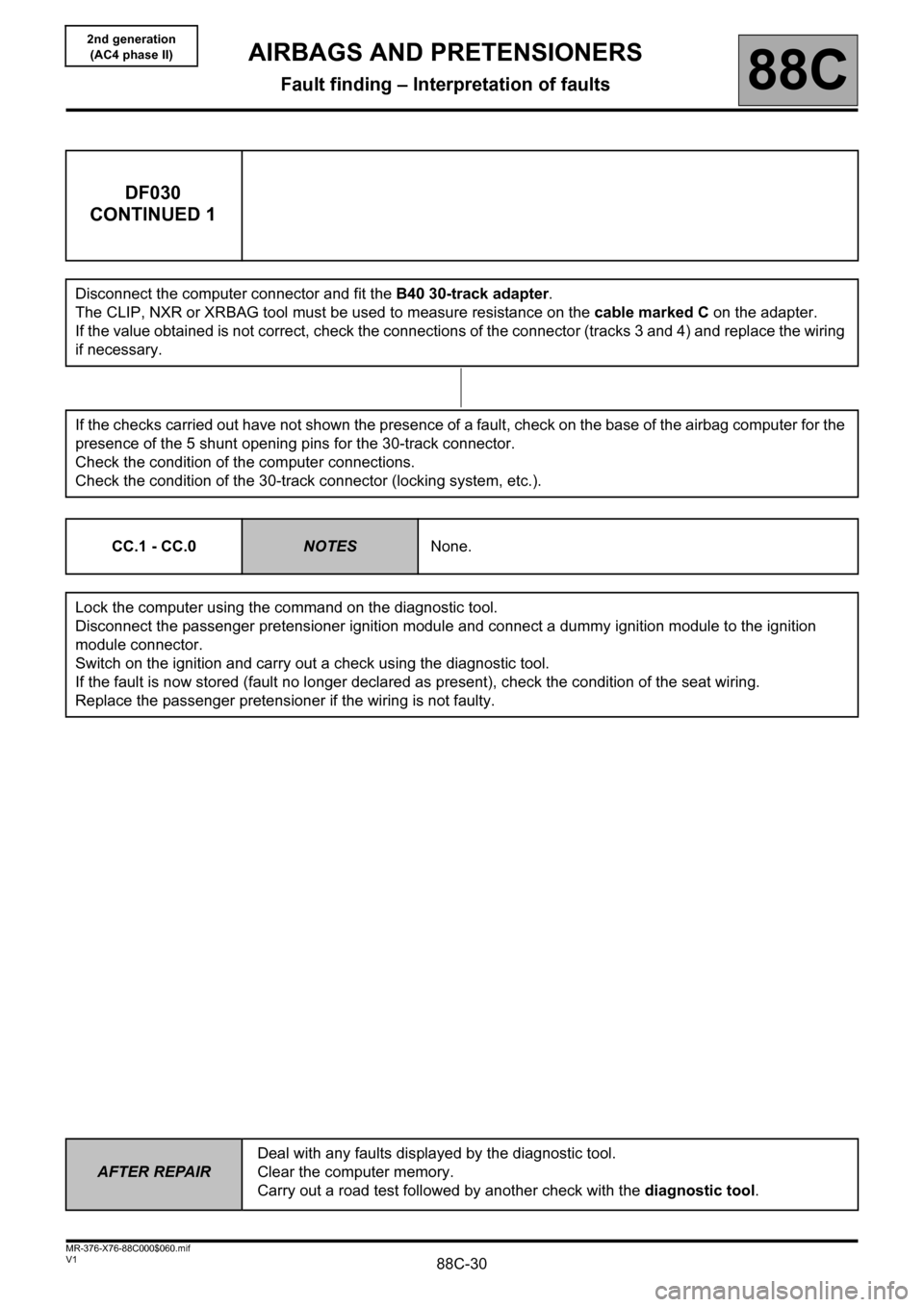
DF030
CONTINUED 1
Disconnect the computer connector and fit the B40 30-track adapter.
The CLIP, NXR or XRBAG tool must be used to measure resistance on the cable marked C on the adapter.
If the value obtained is not correct, check the connections of the connector (tracks 3 and 4) and replace the wiring
if necessary.
If the checks carried out have not shown the presence of a fault, check on the base of the airbag computer for the
presence of the 5 shunt opening pins for the 30-track connector.
Check the condition of the computer connections.
Check the condition of the 30-track connector (locking system, etc.).
CC.1 - CC.0
NOTESNone.
Lock the computer using the command on the diagnostic tool.
Disconnect the passenger pretensioner ignition module and connect a dummy ignition module to the ignition
module connector.
Switch on the ignition and carry out a check using the diagnostic tool.
If the fault is now stored (fault no longer declared as present), check the condition of the seat wiring.
Replace the passenger pretensioner if the wiring is not faulty.