ignition RENAULT KANGOO 2013 X61 / 2.G Diesel DCM 1.2 Injection Owner's Manual
[x] Cancel search | Manufacturer: RENAULT, Model Year: 2013, Model line: KANGOO, Model: RENAULT KANGOO 2013 X61 / 2.GPages: 204, PDF Size: 0.99 MB
Page 69 of 204
13B-69
AFTER
REPAIRDeal with any faults declared by the diagnostic tool.
Clear the computer memory.
Carry out a road test followed by another check with the diagnostic tool.
V1 MR-376-X76-13B000$072.mif
DIESEL INJECTION
Fault finding – Interpretation of faults13B
DCM 1.2 Injection
Program no.: 4C
Vdiag No.: 08
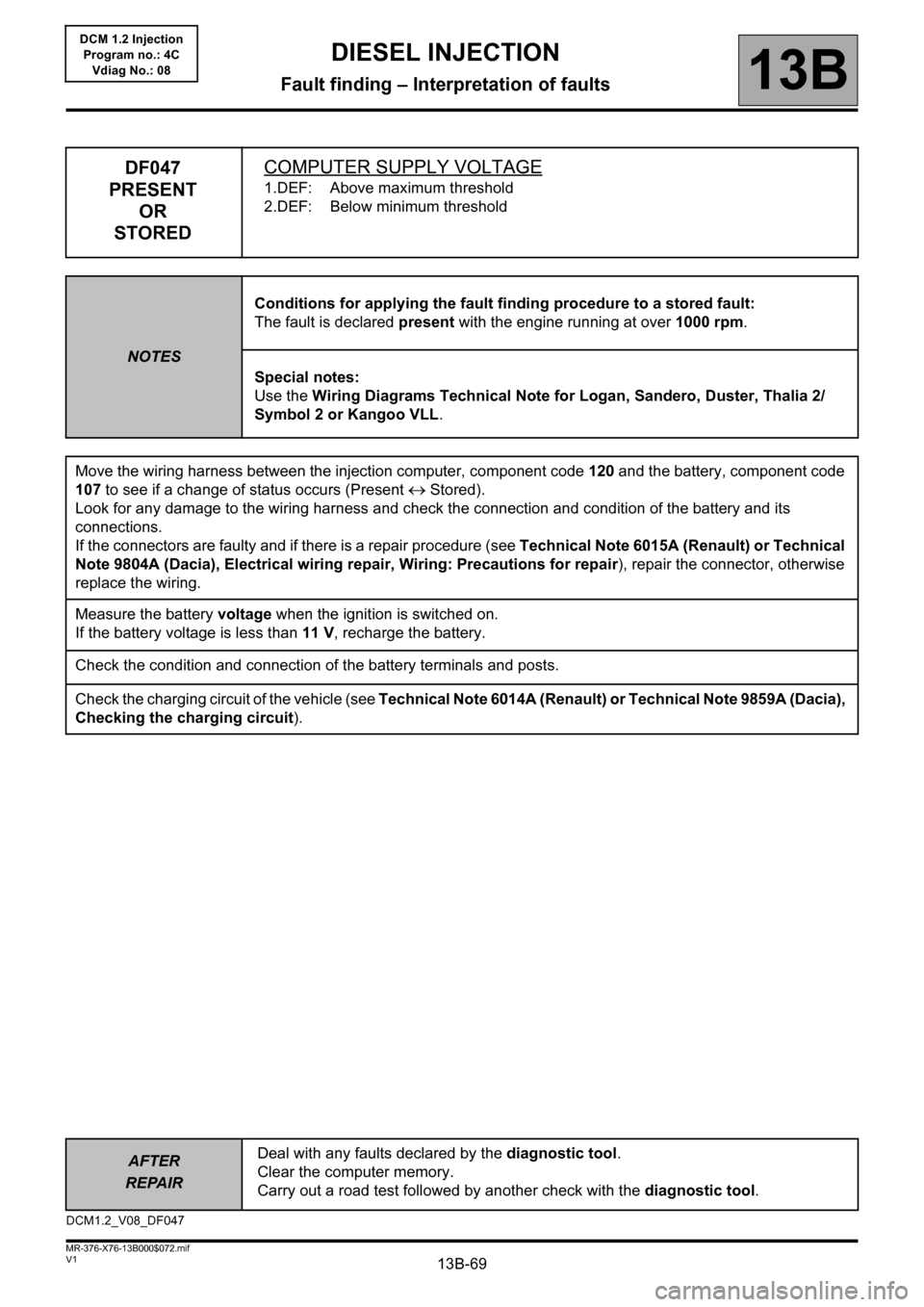
DF047
PRESENT
OR
STOREDCOMPUTER SUPPLY VOLTAGE
1.DEF: Above maximum threshold
2.DEF: Below minimum threshold
NOTESConditions for applying the fault finding procedure to a stored fault:
The fault is declared present with the engine running at over 1000 rpm.
Special notes:
Use the Wiring Diagrams Technical Note for Logan, Sandero, Duster, Thalia 2/
Symbol 2 or Kangoo VLL.
Move the wiring harness between the injection computer, component code 120 and the battery, component code
107 to see if a change of status occurs (Present
Stored).
Look for any damage to the wiring harness and check the connection and condition of the battery and its
connections.
If the connectors are faulty and if there is a repair procedure (see Technical Note 6015A (Renault) or Technical
Note 9804A (Dacia), Electrical wiring repair, Wiring: Precautions for repair), repair the connector, otherwise
replace the wiring.
Measure the battery voltage when the ignition is switched on.
If the battery voltage is less than 11 V, recharge the battery.
Check the condition and connection of the battery terminals and posts.
Check the charging circuit of the vehicle (see Technical Note 6014A (Renault) or Technical Note 9859A (Dacia),
Checking the charging circuit).
DCM1.2_V08_DF047
Page 74 of 204
13B-74
AFTER
REPAIRDeal with any faults declared by the diagnostic tool.
Clear the computer memory.
Carry out a road test followed by another check with the diagnostic tool.
V1 MR-376-X76-13B000$072.mif
DIESEL INJECTION
Fault finding – Interpretation of faults13B
DCM 1.2 Injection
Program no.: 4C
Vdiag No.: 08
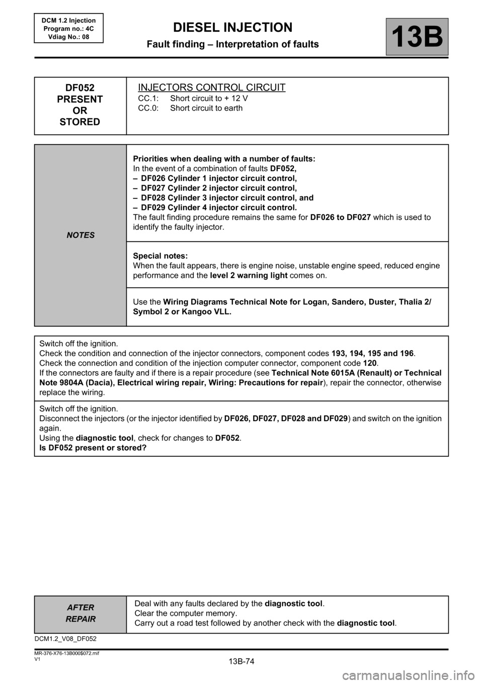
DF052
PRESENT
OR
STOREDINJECTORS CONTROL CIRCUIT
CC.1: Short circuit to + 12 V
CC.0: Short circuit to earth
NOTESPriorities when dealing with a number of faults:
In the event of a combination of faults DF052,
– DF026 Cylinder 1 injector circuit control,
– DF027 Cylinder 2 injector circuit control,
– DF028 Cylinder 3 injector circuit control, and
– DF029 Cylinder 4 injector circuit control.
The fault finding procedure remains the same for DF026 to DF027 which is used to
identify the faulty injector.
Special notes:
When the fault appears, there is engine noise, unstable engine speed, reduced engine
performance and the level 2 warning light comes on.
Use the Wiring Diagrams Technical Note for Logan, Sandero, Duster, Thalia 2/
Symbol 2 or Kangoo VLL.
Switch off the ignition.
Check the condition and connection of the injector connectors, component codes 193, 194, 195 and 196.
Check the connection and condition of the injection computer connector, component code 120.
If the connectors are faulty and if there is a repair procedure (see Technical Note 6015A (Renault) or Technical
Note 9804A (Dacia), Electrical wiring repair, Wiring: Precautions for repair), repair the connector, otherwise
replace the wiring.
Switch off the ignition.
Disconnect the injectors (or the injector identified by DF026, DF027, DF028 and DF029) and switch on the ignition
again.
Using the diagnostic tool, check for changes to DF052.
Is DF052 present or stored?
DCM1.2_V08_DF052
Page 75 of 204
13B-75
AFTER
REPAIRDeal with any faults declared by the diagnostic tool.
Clear the computer memory.
Carry out a road test followed by another check with the diagnostic tool.
V1 MR-376-X76-13B000$072.mif
DIESEL INJECTION
Fault finding – Interpretation of faults13B
DCM 1.2 Injection
Program no.: 4C
Vdiag No.: 08
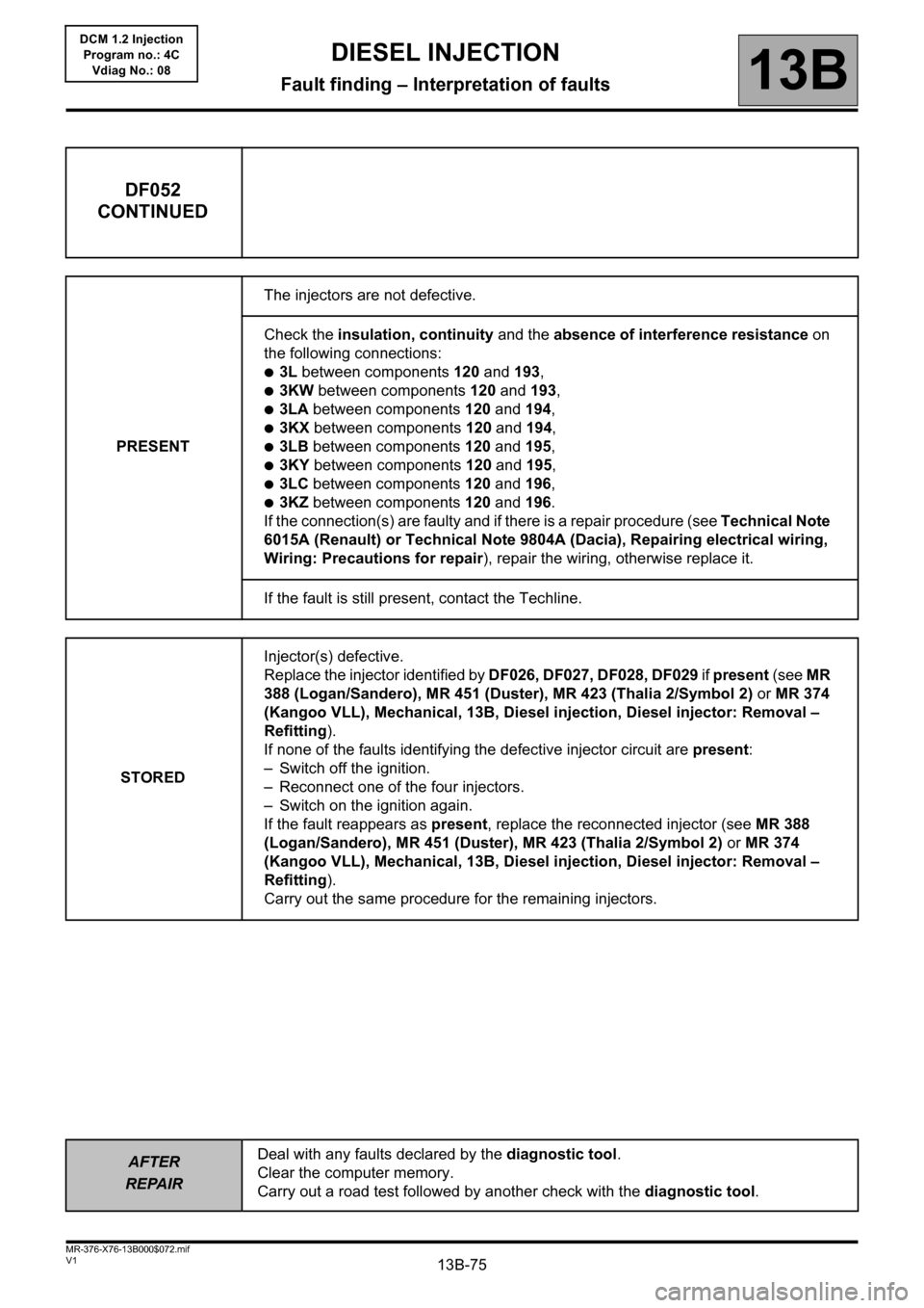
DF052
CONTINUED
PRESENTThe injectors are not defective.
Check the insulation, continuity and the absence of interference resistance on
the following connections:
●3L between components 120 and 193,
●3KW between components 120 and 193,
●3LA between components 120 and 194,
●3KX between components 120 and 194,
●3LB between components 120 and 195,
●3KY between components 120 and 195,
●3LC between components 120 and 196,
●3KZ between components 120 and 196.
If the connection(s) are faulty and if there is a repair procedure (see Technical Note
6015A (Renault) or Technical Note 9804A (Dacia), Repairing electrical wiring,
Wiring: Precautions for repair), repair the wiring, otherwise replace it.
If the fault is still present, contact the Techline.
STOREDInjector(s) defective.
Replace the injector identified by DF026, DF027, DF028, DF029 if present (see MR
388 (Logan/Sandero), MR 451 (Duster), MR 423 (Thalia 2/Symbol 2) or MR 374
(Kangoo VLL), Mechanical, 13B, Diesel injection, Diesel injector: Removal –
Refitting).
If none of the faults identifying the defective injector circuit are present:
– Switch off the ignition.
– Reconnect one of the four injectors.
– Switch on the ignition again.
If the fault reappears as present, replace the reconnected injector (see MR 388
(Logan/Sandero), MR 451 (Duster), MR 423 (Thalia 2/Symbol 2) or MR 374
(Kangoo VLL), Mechanical, 13B, Diesel injection, Diesel injector: Removal –
Refitting).
Carry out the same procedure for the remaining injectors.
Page 79 of 204
13B-79
AFTER
REPAIRDeal with any faults declared by the diagnostic tool.
Clear the computer memory.
Carry out a road test followed by another check with the diagnostic tool.
V1 MR-376-X76-13B000$072.mif
DIESEL INJECTION
Fault finding – Interpretation of faults13B
DCM 1.2 Injection
Program no.: 4C
Vdiag No.: 08
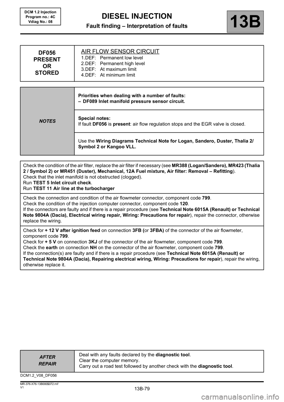
DF056
PRESENT
OR
STOREDAIR FLOW SENSOR CIRCUIT1.DEF: Permanent low level
2.DEF: Permanent high level
3.DEF: At maximum limit
4.DEF: At minimum limit
NOTESPriorities when dealing with a number of faults:
– DF089 Inlet manifold pressure sensor circuit.
Special notes:
If fault DF056 is present: air flow regulation stops and the EGR valve is closed.
Use the Wiring Diagrams Technical Note for Logan, Sandero, Duster, Thalia 2/
Symbol 2 or Kangoo VLL.
Check the condition of the air filter, replace the air filter if necessary (see MR388 (Logan/Sandero), MR423 (Thalia
2 / Symbol 2) or MR451 (Duster), Mechanical, 12A Fuel mixture, Air filter: Removal – Refitting).
Check that the inlet manifold is not obstructed (clogged).
Run TEST 5 Inlet circuit check.
Run TEST 11 Air line at the turbocharger
Check the connection and condition of the air flowmeter connector, component code 799.
Check the condition of the injection computer connector, component code 120.
If the connectors are faulty and if there is a repair procedure (see Technical Note 6015A (Renault) or Technical
Note 9804A (Dacia), Electrical wiring repair, Wiring: Precautions for repair), repair the connector, otherwise
replace the wiring.
Check for + 12 V after ignition feed on connection 3FB (or 3FBA) of the connector of the air flowmeter,
component code 799.
Check for + 5 V on connection 3KJ of the connector of the air flowmeter, component code 799.
Check the earth on connection NH on the connector of the air flowmeter, component code 799.
If the connection(s) are faulty and if there is a repair procedure (see Technical Note 6015A (Renault) or
Technical Note 9804A (Dacia), Repairing electrical wiring, Wiring: Precautions for repair), repair the wiring,
otherwise replace it.
DCM1.2_V08_DF056
Page 81 of 204
13B-81
AFTER
REPAIRDeal with any faults declared by the diagnostic tool.
Clear the computer memory.
Carry out a road test followed by another check with the diagnostic tool.
V1 MR-376-X76-13B000$072.mif
DIESEL INJECTION
Fault finding – Interpretation of faults13B
DCM 1.2 Injection
Program no.: 4C
Vdiag No.: 08
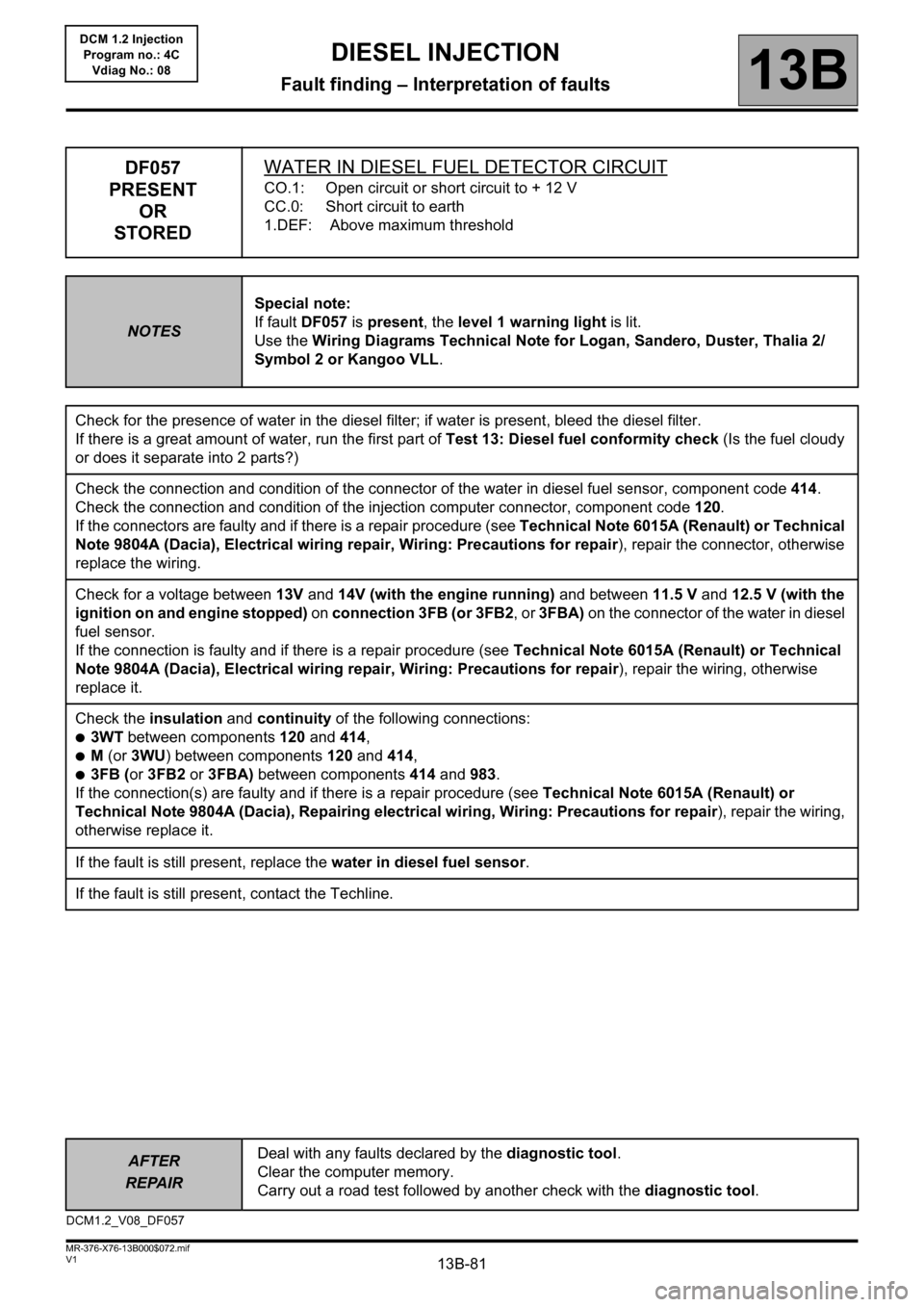
DF057
PRESENT
OR
STOREDWATER IN DIESEL FUEL DETECTOR CIRCUIT
CO.1: Open circuit or short circuit to + 12 V
CC.0: Short circuit to earth
1.DEF: Above maximum threshold
NOTESSpecial note:
If fault DF057 is present, the level 1 warning light is lit.
Use the Wiring Diagrams Technical Note for Logan, Sandero, Duster, Thalia 2/
Symbol 2 or Kangoo VLL.
Check for the presence of water in the diesel filter; if water is present, bleed the diesel filter.
If there is a great amount of water, run the first part of Test 13: Diesel fuel conformity check (Is the fuel cloudy
or does it separate into 2 parts?)
Check the connection and condition of the connector of the water in diesel fuel sensor, component code 414.
Check the connection and condition of the injection computer connector, component code 120.
If the connectors are faulty and if there is a repair procedure (see Technical Note 6015A (Renault) or Technical
Note 9804A (Dacia), Electrical wiring repair, Wiring: Precautions for repair), repair the connector, otherwise
replace the wiring.
Check for a voltage between 13V and 14V (with the engine running) and between 11.5 V and 12.5 V (with the
ignition on and engine stopped) on connection 3FB (or 3FB2, or 3FBA) on the connector of the water in diesel
fuel sensor.
If the connection is faulty and if there is a repair procedure (see Technical Note 6015A (Renault) or Technical
Note 9804A (Dacia), Electrical wiring repair, Wiring: Precautions for repair), repair the wiring, otherwise
replace it.
Check the insulation and continuity of the following connections:
●3WT between components 120 and 414,
●M (or 3WU) between components 120 and 414,
●3FB (or 3FB2 or 3FBA) between components 414 and 983.
If the connection(s) are faulty and if there is a repair procedure (see Technical Note 6015A (Renault) or
Technical Note 9804A (Dacia), Repairing electrical wiring, Wiring: Precautions for repair), repair the wiring,
otherwise replace it.
If the fault is still present, replace the water in diesel fuel sensor.
If the fault is still present, contact the Techline.
DCM1.2_V08_DF057
Page 90 of 204
13B-90
AFTER
REPAIRDeal with any faults declared by the diagnostic tool.
Clear the computer memory.
Carry out a road test followed by another check with the diagnostic tool.
V1 MR-376-X76-13B000$072.mif
DIESEL INJECTION
Fault finding – Interpretation of faults13B
DCM 1.2 Injection
Program no.: 4C
Vdiag No.: 08
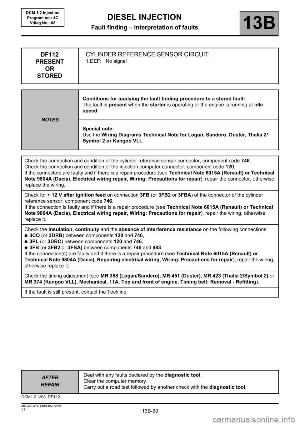
DF112
PRESENT
OR
STOREDCYLINDER REFERENCE SENSOR CIRCUIT
1.DEF: No signal
NOTESConditions for applying the fault finding procedure to a stored fault:
The fault is present when the starter is operating or the engine is running at idle
speed.
Special note:
Use the Wiring Diagrams Technical Note for Logan, Sandero, Duster, Thalia 2/
Symbol 2 or Kangoo VLL.
Check the connection and condition of the cylinder reference sensor connector, component code 746.
Check the connection and condition of the injection computer connector, component code 120.
If the connectors are faulty and if there is a repair procedure (see Technical Note 6015A (Renault) or Technical
Note 9804A (Dacia), Electrical wiring repair, Wiring: Precautions for repair), repair the connector, otherwise
replace the wiring.
Check for + 12 V after ignition feed on connection 3FB (or 3FB2 or 3FBA) of the connector of the cylinder
reference sensor, component code 746.
If the connection is faulty and if there is a repair procedure (see Technical Note 6015A (Renault) or Technical
Note 9804A (Dacia), Electrical wiring repair, Wiring: Precautions for repair), repair the wiring, otherwise
replace it.
Check the insulation, continuity and the absence of interference resistance on the following connections:
●3CQ (or 3DRB) between components 120 and 746,
●3PL (or 3DRC) between components 120 and 746,
●3FB (or 3FB2 or 3FBA) between components 746 and 983.
If the connection(s) are faulty and if there is a repair procedure (see Technical Note 6015A (Renault) or
Technical Note 9804A (Dacia), Repairing electrical wiring, Wiring: Precautions for repair), repair the wiring,
otherwise replace it.
Check the timing adjustment (see MR 388 (Logan/Sandero), MR 451 (Duster), MR 423 (Thalia 2/Symbol 2) or
MR 374 (Kangoo VLL), Mechanical, 11A, Top and front of engine, Timing belt: Removal - Refitting).
If the fault is still present, contact the Techline.
DCM1.2_V08_DF112
Page 100 of 204
13B-100
AFTER
REPAIRDeal with any faults declared by the diagnostic tool.
Clear the computer memory.
Carry out a road test followed by another check with the diagnostic tool.
V1 MR-376-X76-13B000$072.mif
DIESEL INJECTION
Fault finding – Interpretation of faults13B
DCM 1.2 Injection
Program no.: 4C
Vdiag No.: 08
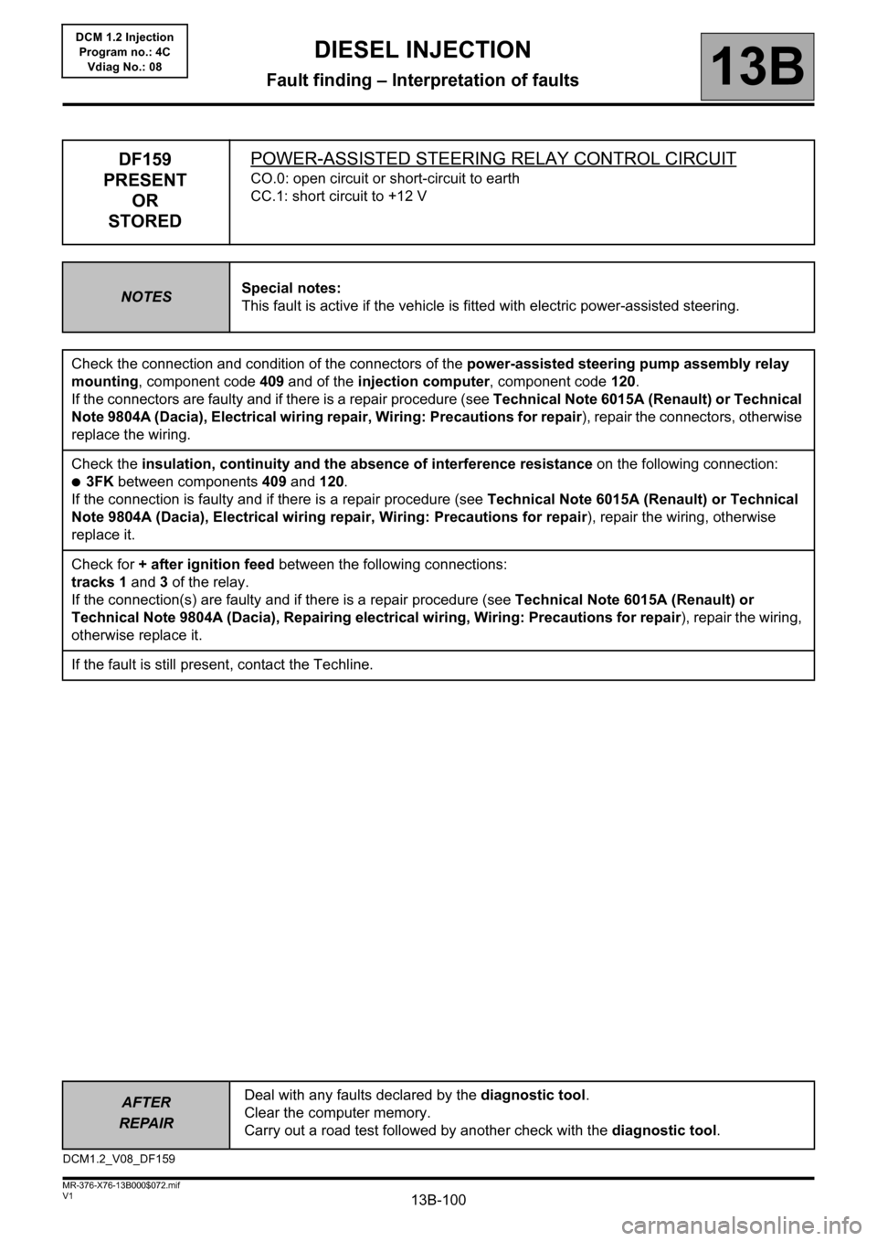
DF159
PRESENT
OR
STOREDPOWER-ASSISTED STEERING RELAY CONTROL CIRCUIT
CO.0: open circuit or short-circuit to earth
CC.1: short circuit to +12 V
NOTESSpecial notes:
This fault is active if the vehicle is fitted with electric power-assisted steering.
Check the connection and condition of the connectors of the power-assisted steering pump assembly relay
mounting, component code 409 and of the injection computer, component code 120.
If the connectors are faulty and if there is a repair procedure (see Technical Note 6015A (Renault) or Technical
Note 9804A (Dacia), Electrical wiring repair, Wiring: Precautions for repair), repair the connectors, otherwise
replace the wiring.
Check the insulation, continuity and the absence of interference resistance on the following connection:
●3FK between components 409 and 120.
If the connection is faulty and if there is a repair procedure (see Technical Note 6015A (Renault) or Technical
Note 9804A (Dacia), Electrical wiring repair, Wiring: Precautions for repair), repair the wiring, otherwise
replace it.
Check for + after ignition feed between the following connections:
tracks 1 and 3 of the relay.
If the connection(s) are faulty and if there is a repair procedure (see Technical Note 6015A (Renault) or
Technical Note 9804A (Dacia), Repairing electrical wiring, Wiring: Precautions for repair), repair the wiring,
otherwise replace it.
If the fault is still present, contact the Techline.
DCM1.2_V08_DF159
Page 112 of 204
13B-112
AFTER
REPAIRDeal with any faults declared by the diagnostic tool.
Clear the computer memory.
Carry out a road test followed by another check with the diagnostic tool.
V1 MR-376-X76-13B000$072.mif
DIESEL INJECTION
Fault finding – Interpretation of faults13B
DCM 1.2 Injection
Program no.: 4C
Vdiag No.: 08
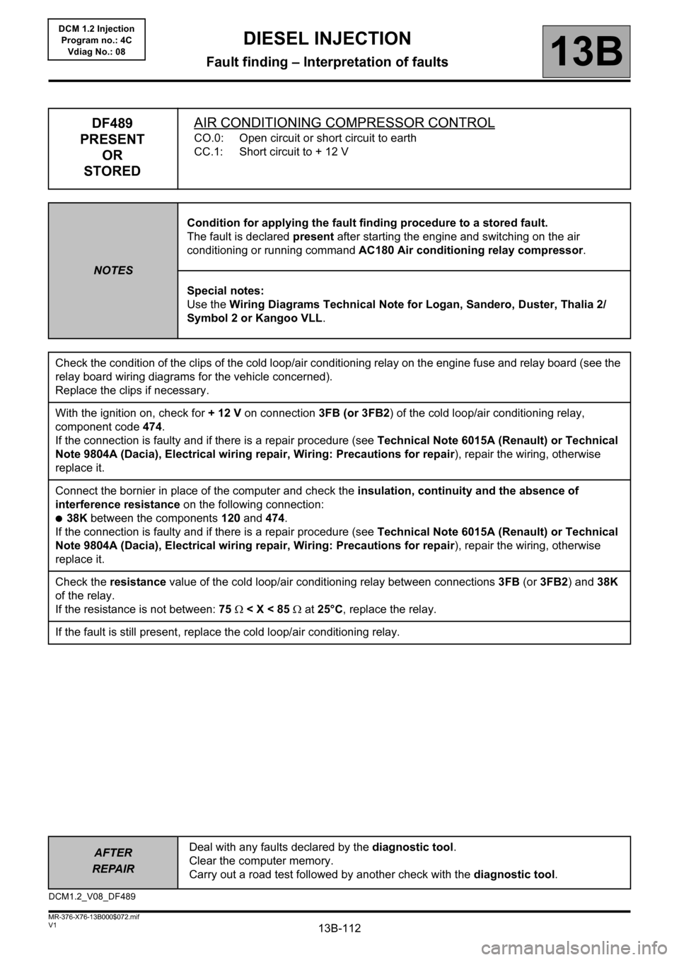
DF489
PRESENT
OR
STOREDAIR CONDITIONING COMPRESSOR CONTROL
CO.0: Open circuit or short circuit to earth
CC.1: Short circuit to + 12 V
NOTESCondition for applying the fault finding procedure to a stored fault.
The fault is declared present after starting the engine and switching on the air
conditioning or running command AC180 Air conditioning relay compressor.
Special notes:
Use the Wiring Diagrams Technical Note for Logan, Sandero, Duster, Thalia 2/
Symbol 2 or Kangoo VLL.
Check the condition of the clips of the cold loop/air conditioning relay on the engine fuse and relay board (see the
relay board wiring diagrams for the vehicle concerned).
Replace the clips if necessary.
With the ignition on, check for + 12 V on connection 3FB (or 3FB2) of the cold loop/air conditioning relay,
component code 474.
If the connection is faulty and if there is a repair procedure (see Technical Note 6015A (Renault) or Technical
Note 9804A (Dacia), Electrical wiring repair, Wiring: Precautions for repair), repair the wiring, otherwise
replace it.
Connect the bornier in place of the computer and check the insulation, continuity and the absence of
interference resistance on the following connection:
●38K between the components 120 and 474.
If the connection is faulty and if there is a repair procedure (see Technical Note 6015A (Renault) or Technical
Note 9804A (Dacia), Electrical wiring repair, Wiring: Precautions for repair), repair the wiring, otherwise
replace it.
Check the resistance value of the cold loop/air conditioning relay between connections 3FB (or 3FB2) and 38K
of the relay.
If the resistance is not between: 75 < X < 85 at 25°C, replace the relay.
If the fault is still present, replace the cold loop/air conditioning relay.
DCM1.2_V08_DF489
Page 115 of 204
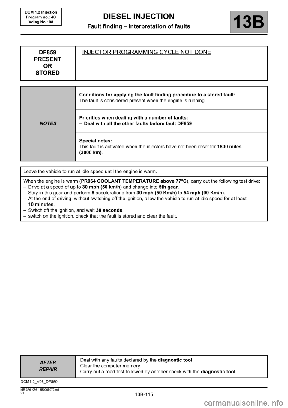
13B-115
AFTER
REPAIRDeal with any faults declared by the diagnostic tool.
Clear the computer memory.
Carry out a road test followed by another check with the diagnostic tool.
V1 MR-376-X76-13B000$072.mif
DIESEL INJECTION
Fault finding – Interpretation of faults13B
DCM 1.2 Injection
Program no.: 4C
Vdiag No.: 08
DF859
PRESENT
OR
STOREDINJECTOR PROGRAMMING CYCLE NOT DONE
NOTESConditions for applying the fault finding procedure to a stored fault:
The fault is considered present when the engine is running.
Priorities when dealing with a number of faults:
– Deal with all the other faults before fault DF859
Special notes:
This fault is activated when the injectors have not been reset for 1800 miles
(3000 km).
Leave the vehicle to run at idle speed until the engine is warm.
When the engine is warm (PR064 COOLANT TEMPERATURE above 77°C), carry out the following test drive:
– Drive at a speed of up to 30 mph (50 km/h) and change into 5th gear.
– Stay in this gear and perform 8 accelerations from 30 mph (50 Km/h) to 54 mph (90 Km/h).
– At the end of driving: without switching off the ignition, allow the vehicle to run at idle speed for at least
10 minutes.
– Switch off the ignition, and wait 30 seconds.
– switch on the ignition, check that the fault is stored and clear the fault.
DCM1.2_V08_DF859
Page 116 of 204
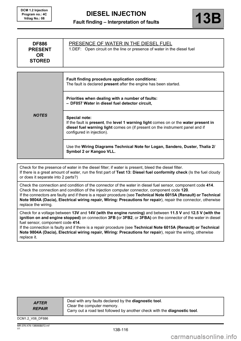
13B-116
AFTER
REPAIRDeal with any faults declared by the diagnostic tool.
Clear the computer memory.
Carry out a road test followed by another check with the diagnostic tool.
V1 MR-376-X76-13B000$072.mif
DIESEL INJECTION
Fault finding – Interpretation of faults13B
DCM 1.2 Injection
Program no.: 4C
Vdiag No.: 08
DF886
PRESENT
OR
STOREDPRESENCE OF WATER IN THE DIESEL FUEL
1.DEF: Open circuit on the line or presence of water in the diesel fuel
NOTESFault finding procedure application conditions:
The fault is declared present after the engine has been started.
Priorities when dealing with a number of faults:
– DF057 Water in diesel fuel detector circuit,
Special note:
If the fault is present, the level 1 warning light comes on or the water present in
diesel fuel warning light comes on (if present on the instrument panel and if
configured in injection).
Use the Wiring Diagrams Technical Note for Logan, Sandero, Duster, Thalia 2/
Symbol 2 or Kangoo VLL.
Check for the presence of water in the diesel filter; if water is present, bleed the diesel filter.
If there is a great amount of water, run the first part of Test 13: Diesel fuel conformity check (Is the fuel cloudy
or does it separate into 2 parts?)
Check the connection and condition of the connector of the water in diesel fuel sensor, component code 414.
Check the connection and condition of the injection computer connector, component code 120.
If the connectors are faulty and if there is a repair procedure (see Technical Note 6015A (Renault) or Technical
Note 9804A (Dacia), Electrical wiring repair, Wiring: Precautions for repair), repair the connector, otherwise
replace the wiring.
Check for a voltage between 13V and 14V (with the engine running) and between 11.5 V and 12.5 V (with the
ignition on and engine stopped) on connection 3FB (or 3FB2, or 3FBA) on the connector of the water in diesel
fuel sensor, component code 414.
If the connection is faulty and if there is a repair procedure (see Technical Note 6015A (Renault) or Technical
Note 9804A (Dacia), Electrical wiring repair, Wiring: Precautions for repair), repair the wiring, otherwise
replace it.
DCM1.2_V08_DF886