display RENAULT KANGOO 2013 X61 / 2.G Diesel DCM 1.2 Injection Workshop Manual
[x] Cancel search | Manufacturer: RENAULT, Model Year: 2013, Model line: KANGOO, Model: RENAULT KANGOO 2013 X61 / 2.GPages: 204, PDF Size: 0.99 MB
Page 3 of 204
13B-3V1 MR-376-X76-13B000$010.mif
DIESEL INJECTION
Fault finding – Introduction13B
DCM 1.2 Injection
Program no.: 4C
Vdiag No.: 08
Faults
Faults are declared either present or stored (depending on whether they appeared in a certain context and have
disappeared since, or whether they remain present but have not been diagnosed within the current context).
The present or stored status of the faults should be taken into consideration when the diagnostic tool is used after
the + after ignition feed has been activated (without any of the system components being activated).
For a present fault, apply the procedure described in the Interpretation of faults section.
For a stored fault, note the faults displayed and apply the Notes section.
If the fault is confirmed when the instructions are applied, the fault is present. Deal with the fault.
If the fault is not confirmed, check:
– the electrical lines which correspond to the fault,
– the connectors on these lines (corrosion, bent pins, etc.),
– the resistance of the faulty component,
– the condition of the wires (melted or cut insulation, wear).
Conformity check
The purpose of the conformity check is to check data that does not produce a fault on the diagnostic tool when the
data is inconsistent. Therefore, this stage is used to:
– carry out fault finding on faults that do not have a fault display, and which may correspond to a customer complaint,
– check that the system is operating correctly and that there is no risk of a fault recurring after repair.
This section gives the fault finding procedures for statuses and parameters and the conditions for checking them.
If a status is not behaving normally or a parameter is outside permitted tolerance values, you should consult the
corresponding fault finding page.
Customer complaints - Fault finding chart
If the test with the diagnostic tool is OK but the customer complaint is still present, the fault should be dealt with by
customer complaints.
A synopsis of the general procedure to follow is provided on the following page in the form of a flow chart.
Page 15 of 204
13B-15V1 MR-376-X76-13B000$030.mif
DIESEL INJECTION
Fault finding – System operation13B
DCM 1.2 Injection
Program no.: 4C
Vdiag No.: 08
Instrument panel display
The computer manages the data display on the instrument panel relating to engine operation.
There are six functions concerned:
–the On board diagnostics MIL (Malfunction Indicator Lamp),
– pre-postheating,
– the coolant temperature,
– engine problems; Level 1 (non-critical fault) and Level 2 (emergency stop).
– detection of water in the fuel (depending on instrument panel).
These six functions are represented using four indicator lights.
Pre-postheating and electronic fault warning light (Level 1)
This light is used to indicate that the heater plugs are preheating and as a system fault indicator light:
– Continuously illuminated during + after ignition feed: indicates preheating of the heater plugs.
– Flashing after preheating and an automatic 3-second stop indicates a Level 1 fault (the function is not working
optimally and safety levels are reduced). The user must carry out repairs as soon as possible).
Engine coolant temperature warning light (Level 2)
This indicator light is used both as an in-operation indicator light and as a system fault warning light. It illuminates for
3 seconds when the power is switched on (automatic test procedure).
Continuously illuminated during + after ignition feed: indicates engine overheating or a Level 2 fault.
OBD warning light
This warning light is used to alert the driver of any injection faults that could lead to excessive pollution, or if the OBD
system has been deactivated.
The injection computer requests illumination of the OBD warning light for a present fault only after three successive
driving cycles.
The 3 second visual inspection when the ignition is switched on (automatic test procedure managed by the
instrument panel) is carried out by the injection computer.
Page 71 of 204
13B-71
AFTER
REPAIRDeal with any faults declared by the diagnostic tool.
Clear the computer memory.
Carry out a road test followed by another check with the diagnostic tool.
V1 MR-376-X76-13B000$072.mif
DIESEL INJECTION
Fault finding – Interpretation of faults13B
DCM 1.2 Injection
Program no.: 4C
Vdiag No.: 08
DF049
PRESENT
OR
STOREDREFRIGERANT SENSOR CIRCUIT
CO.1: Open circuit or short circuit to + 12 V
CC.0: Short circuit to earth
NOTESConditions for applying the fault finding procedure to a stored fault:
Apply the fault finding procedure below if the fault is present or stored.
Priority when dealing with a number of faults:
– DF113 Sensor supply voltage.
Special notes:
Use the Wiring Diagrams Technical Note for Logan, Sandero, Duster, Thalia 2/
Symbol 2 or Kangoo VLL.
Display PR037 Refrigerant pressure; if the value is less than 2 bar, top up the refrigerant fluid (see MR 388
(Logan/Sandero), MR 423 (Thalia 2/Symbol 2), MR 451 (Duster), or MR 374 (Kangoo VLL), Mechanical, 62A,
Air conditioning, Refrigerant circuit: Draining – Filling).
Move the wiring harness between the injection computer, component code 120 and the refrigerant pressure
sensor, component code 1202 to see if the status changes (present
stored).
Look for any damage to the wiring and check the condition and connection of the refrigerant pressure sensor and
its connections.
If the connector is faulty and if there is a repair procedure (see Technical Note 6015A (Renault) or Technical
Note 9804A (Dacia), Electrical wiring repair, Wiring: Precautions for repair), repair the connector, otherwise
replace the wiring.
Check the connection and condition of the injection computer connector, component code 120.
If the connector is faulty and if there is a repair procedure (see Technical Note 6015A (Renault) or Technical
Note 9804A (Dacia), Electrical wiring repair, Wiring: Precautions for repair), repair the connector, otherwise
replace the wiring.
DCM1.2_V08_DF049
Page 73 of 204
13B-73
AFTER
REPAIRDeal with any faults declared by the diagnostic tool.
Clear the computer memory.
Carry out a road test followed by another check with the diagnostic tool.
V1 MR-376-X76-13B000$072.mif
DIESEL INJECTION
Fault finding – Interpretation of faults13B
DCM 1.2 Injection
Program no.: 4C
Vdiag No.: 08
DF050
PRESENT
OR
STOREDBRAKE SWITCH CIRCUIT
CO.0: Open circuit or short circuit to earth
1.DEF: No signal
NOTESSpecial notes:
The fault is declared present when decelerating, when the brake pedal is depressed.
Use the Wiring Diagrams Technical Note for Logan, Sandero, Duster, Thalia 2/
Symbol 2 or Kangoo VLL.
Conditions for applying the fault finding procedure to a stored fault:
Apply the fault finding procedure below if the fault is present or stored.
Check that brake switch works correctly by displaying ET039 Brake pedal.
Check the connection and condition of the brake light switch connector, component code160.
Check the connection and condition of the injection computer connector, component code 120.
If the connectors are faulty and if there is a repair procedure (see Technical Note 6015A (Renault) or Technical
Note 9804A (Dacia), Electrical wiring repair, Wiring: Precautions for repair), repair the connector, otherwise
replace the wiring.
Check for + 12 V on the supply of the brake light switch on connections AP1 or AP10.
If the connection(s) are faulty and if there is a repair procedure (see Technical Note 6015A (Renault) or
Technical Note 9804A (Dacia), Repairing electrical wiring, Wiring: Precautions for repair), repair the wiring,
otherwise replace it.
Check the insulation, continuity and the absence of interference resistance on the following connections:
●65A between components 120 and 160,
●AP1 or AP10 between components 160 and 1016 or 260.
If the connection(s) are faulty and if there is a repair procedure (see Technical Note 6015A (Renault) or
Technical Note 9804A (Dacia), Repairing electrical wiring, Wiring: Precautions for repair), repair the wiring,
otherwise replace it.
If the fault is still present, contact the Techline.
DCM1.2_V08_DF050
Page 76 of 204
13B-76
AFTER
REPAIRDeal with any faults declared by the diagnostic tool.
Clear the computer memory.
Carry out a road test followed by another check with the diagnostic tool.
V1 MR-376-X76-13B000$072.mif
DIESEL INJECTION
Fault finding – Interpretation of faults13B
DCM 1.2 Injection
Program no.: 4C
Vdiag No.: 08
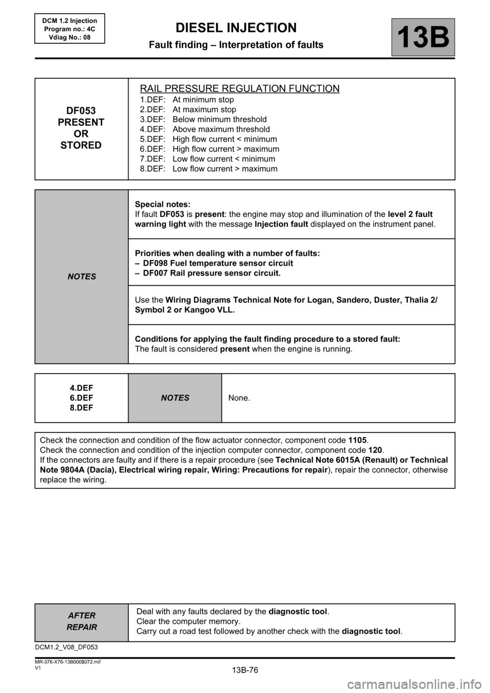
DF053
PRESENT
OR
STOREDRAIL PRESSURE REGULATION FUNCTION
1.DEF: At minimum stop
2.DEF: At maximum stop
3.DEF: Below minimum threshold
4.DEF: Above maximum threshold
5.DEF: High flow current < minimum
6.DEF: High flow current > maximum
7.DEF: Low flow current < minimum
8.DEF: Low flow current > maximum
NOTESSpecial notes:
If fault DF053 is present: the engine may stop and illumination of the level 2 fault
warning light with the message Injection fault displayed on the instrument panel.
Priorities when dealing with a number of faults:
– DF098 Fuel temperature sensor circuit
– DF007 Rail pressure sensor circuit.
Use the Wiring Diagrams Technical Note for Logan, Sandero, Duster, Thalia 2/
Symbol 2 or Kangoo VLL.
Conditions for applying the fault finding procedure to a stored fault:
The fault is considered present when the engine is running.
4.DEF
6.DEF
8.DEF
NOTESNone.
Check the connection and condition of the flow actuator connector, component code 1105.
Check the connection and condition of the injection computer connector, component code 120.
If the connectors are faulty and if there is a repair procedure (see Technical Note 6015A (Renault) or Technical
Note 9804A (Dacia), Electrical wiring repair, Wiring: Precautions for repair), repair the connector, otherwise
replace the wiring.
DCM1.2_V08_DF053
Page 109 of 204
13B-109
AFTER
REPAIRDeal with any faults declared by the diagnostic tool.
Clear the computer memory.
Carry out a road test followed by another check with the diagnostic tool.
V1 MR-376-X76-13B000$072.mif
DIESEL INJECTION
Fault finding – Interpretation of faults13B
DCM 1.2 Injection
Program no.: 4C
Vdiag No.: 08
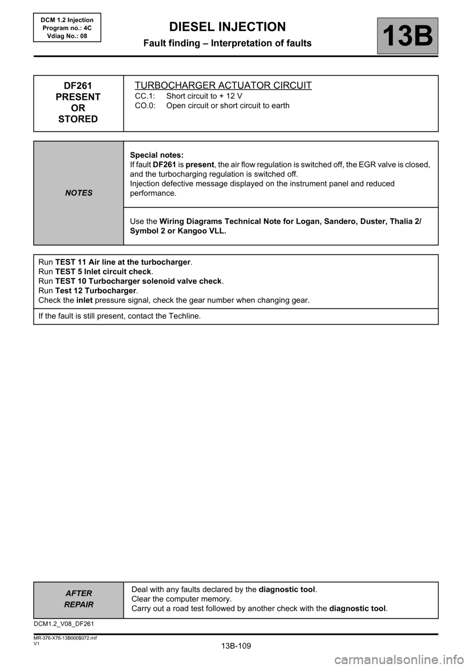
DF261
PRESENT
OR
STOREDTURBOCHARGER ACTUATOR CIRCUIT
CC.1: Short circuit to + 12 V
CO.0: Open circuit or short circuit to earth
NOTESSpecial notes:
If fault DF261 is present, the air flow regulation is switched off, the EGR valve is closed,
and the turbocharging regulation is switched off.
Injection defective message displayed on the instrument panel and reduced
performance.
Use the Wiring Diagrams Technical Note for Logan, Sandero, Duster, Thalia 2/
Symbol 2 or Kangoo VLL.
Run TEST 11 Air line at the turbocharger.
Run TEST 5 Inlet circuit check.
Run TEST 10 Turbocharger solenoid valve check.
Run Test 12 Turbocharger.
Check the inlet pressure signal, check the gear number when changing gear.
If the fault is still present, contact the Techline.
DCM1.2_V08_DF261
Page 119 of 204
13B-119V1 MR-376-X76-13B000$080.mif
13B
DCM 1.2 Injection
Program no.: 4C
Vdiag No.: 08
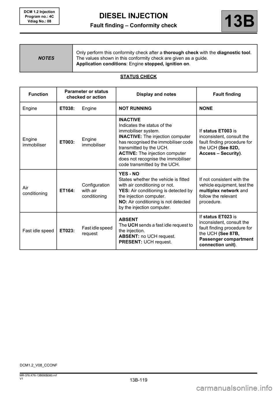
STATUS CHECK
NOTESOnly perform this conformity check after a thorough check with the diagnostic tool.
The values shown in this conformity check are given as a guide.
Application conditions: Engine stopped, ignition on.
FunctionParameter or status
checked or actionDisplay and notes Fault finding
EngineET038:EngineNOT RUNNING NONE
Engine
immobiliserET003:Engine
immobiliserINACTIVE
Indicates the status of the
immobiliser system.
INACTIVE: The injection computer
has recognised the immobiliser code
transmitted by the UCH.
ACTIVE: The injection computer
does not recognise the immobiliser
code transmitted by the UCH.If status ET003 is
inconsistent, consult the
fault finding procedure for
the UCH (See 82D,
Access – Security).
Air
conditioningET164:Configuration
with air
conditioningYES - NO
States whether the vehicle is fitted
with air conditioning or not.
YES: Air conditioning is detected by
the injection computer.
NO: Air conditioning is not detected
by the injection computer.If not consistent with the
vehicle equipment, test the
multiplex network and
follow the relevant
procedure.
Fast idle speedET023:Fast idle speed
requestABSENT
The UCH sends a fast idle request to
the injection.
ABSENT: no UCH request.
PRESENT: UCH request.If status ET023 is
inconsistent, consult the
fault finding procedure for
the UCH (See 87B,
Passenger compartment
connection unit).
DCM1.2_V08_CCONF
DIESEL INJECTION
Fault finding – Conformity check
Page 120 of 204

13B-120V1 MR-376-X76-13B000$080.mif
DIESEL INJECTION
Fault finding – Conformity check13B
DCM 1.2 Injection
Program no.: 4C
Vdiag No.: 08
STATUS CHECK (CONTINUED 1)
NOTESOnly perform this conformity check after a thorough check with the diagnostic tool.
The values shown in this conformity check are given as a guide.
Application conditions: Engine stopped, ignition on.
FunctionParameter or status
checked or actionDisplay and notes Fault finding
Air
conditioningET116:Climate control
authorisationNO
YES: The UCH should send an
activation request to the injection.
The coolant pressure sensor must
not be defective. Satisfactory engine
operating conditions (coolant
temperature, engine load etc.).
NO: One of the above conditions has
not been fulfilled.NONE
EGRET008:EGR solenoid
valve controlINACTIVE
Shows the condition of the EGR
valve control.
INACTIVE: The valve is not
controlled by the computer.
ACTIVE: The valve is controlled by
the computer.NONE
PreheatingET007:Pre-
postheating
controlACTIVE/INACTIVE
Shows the status of the preheating
unit control.In the event of a fault,
consult the interpretation
of fault DF017 Preheating
unit control circuit.
Page 121 of 204
13B-121V1 MR-376-X76-13B000$080.mif
DIESEL INJECTION
Fault finding – Conformity check13B
DCM 1.2 Injection
Program no.: 4C
Vdiag No.: 08
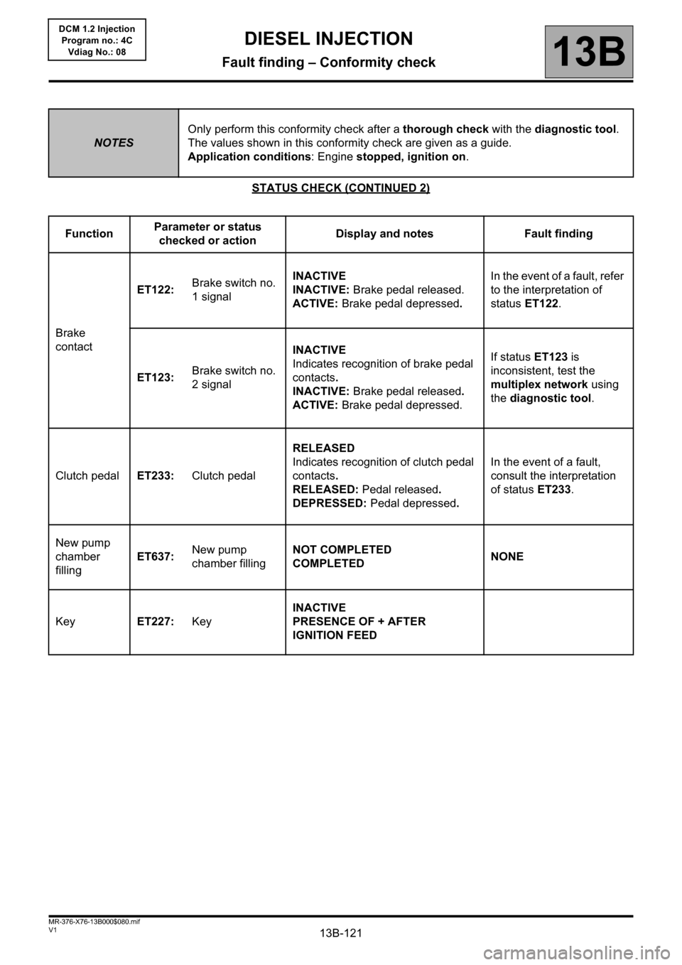
STATUS CHECK (CONTINUED 2)
NOTESOnly perform this conformity check after a thorough check with the diagnostic tool.
The values shown in this conformity check are given as a guide.
Application conditions: Engine stopped, ignition on.
FunctionParameter or status
checked or actionDisplay and notes Fault finding
Brake
contactET122:Brake switch no.
1 signalINACTIVE
INACTIVE: Brake pedal released.
ACTIVE: Brake pedal depressed.In the event of a fault, refer
to the interpretation of
status ET122.
ET123:Brake switch no.
2 signalINACTIVE
Indicates recognition of brake pedal
contacts.
INACTIVE: Brake pedal released.
ACTIVE: Brake pedal depressed.If status ET123 is
inconsistent, test the
multiplex network using
the diagnostic tool.
Clutch pedalET233:Clutch pedalRELEASED
Indicates recognition of clutch pedal
contacts.
RELEASED: Pedal released.
DEPRESSED: Pedal depressed.In the event of a fault,
consult the interpretation
of status ET233.
New pump
chamber
fillingET637:New pump
chamber fillingNOT COMPLETED
COMPLETEDNONE
KeyET227:KeyINACTIVE
PRESENCE OF + AFTER
IGNITION FEED
Page 122 of 204
13B-122V1 MR-376-X76-13B000$080.mif
DIESEL INJECTION
Fault finding – Conformity check13B
DCM 1.2 Injection
Program no.: 4C
Vdiag No.: 08
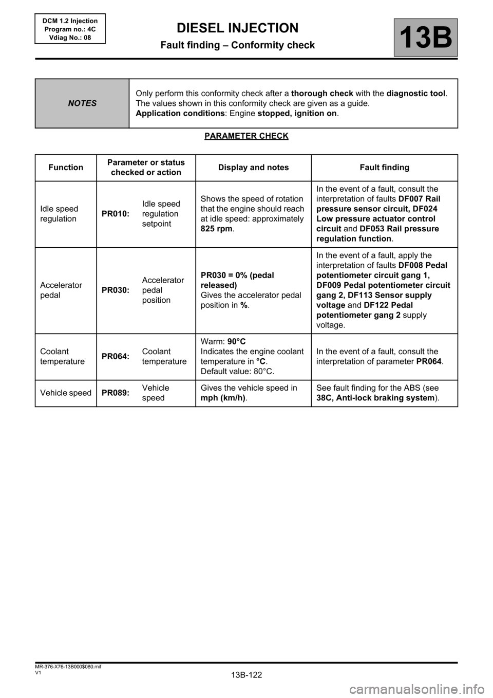
PARAMETER CHECK
NOTESOnly perform this conformity check after a thorough check with the diagnostic tool.
The values shown in this conformity check are given as a guide.
Application conditions: Engine stopped, ignition on.
FunctionParameter or status
checked or actionDisplay and notes Fault finding
Idle speed
regulationPR010:Idle speed
regulation
setpointShows the speed of rotation
that the engine should reach
at idle speed: approximately
825 rpm.In the event of a fault, consult the
interpretation of faults DF007 Rail
pressure sensor circuit, DF024
Low pressure actuator control
circuit and DF053 Rail pressure
regulation function.
Accelerator
pedalPR030:Accelerator
pedal
positionPR030 = 0% (pedal
released)
Gives the accelerator pedal
position in %.In the event of a fault, apply the
interpretation of faults DF008 Pedal
potentiometer circuit gang 1,
DF009 Pedal potentiometer circuit
gang 2, DF113 Sensor supply
voltage and DF122 Pedal
potentiometer gang 2 supply
voltage.
Coolant
temperaturePR064:Coolant
temperatureWarm: 90°C
Indicates the engine coolant
temperature in °C.
Default value: 80°C.In the event of a fault, consult the
interpretation of parameter PR064.
Vehicle speedPR089:Vehicle
speedGives the vehicle speed in
mph (km/h).See fault finding for the ABS (see
38C, Anti-lock braking system).