fuse diagram RENAULT KANGOO 2013 X61 / 2.G Diesel DCM 1.2 Injection Workshop Manual
[x] Cancel search | Manufacturer: RENAULT, Model Year: 2013, Model line: KANGOO, Model: RENAULT KANGOO 2013 X61 / 2.GPages: 204, PDF Size: 0.99 MB
Page 41 of 204
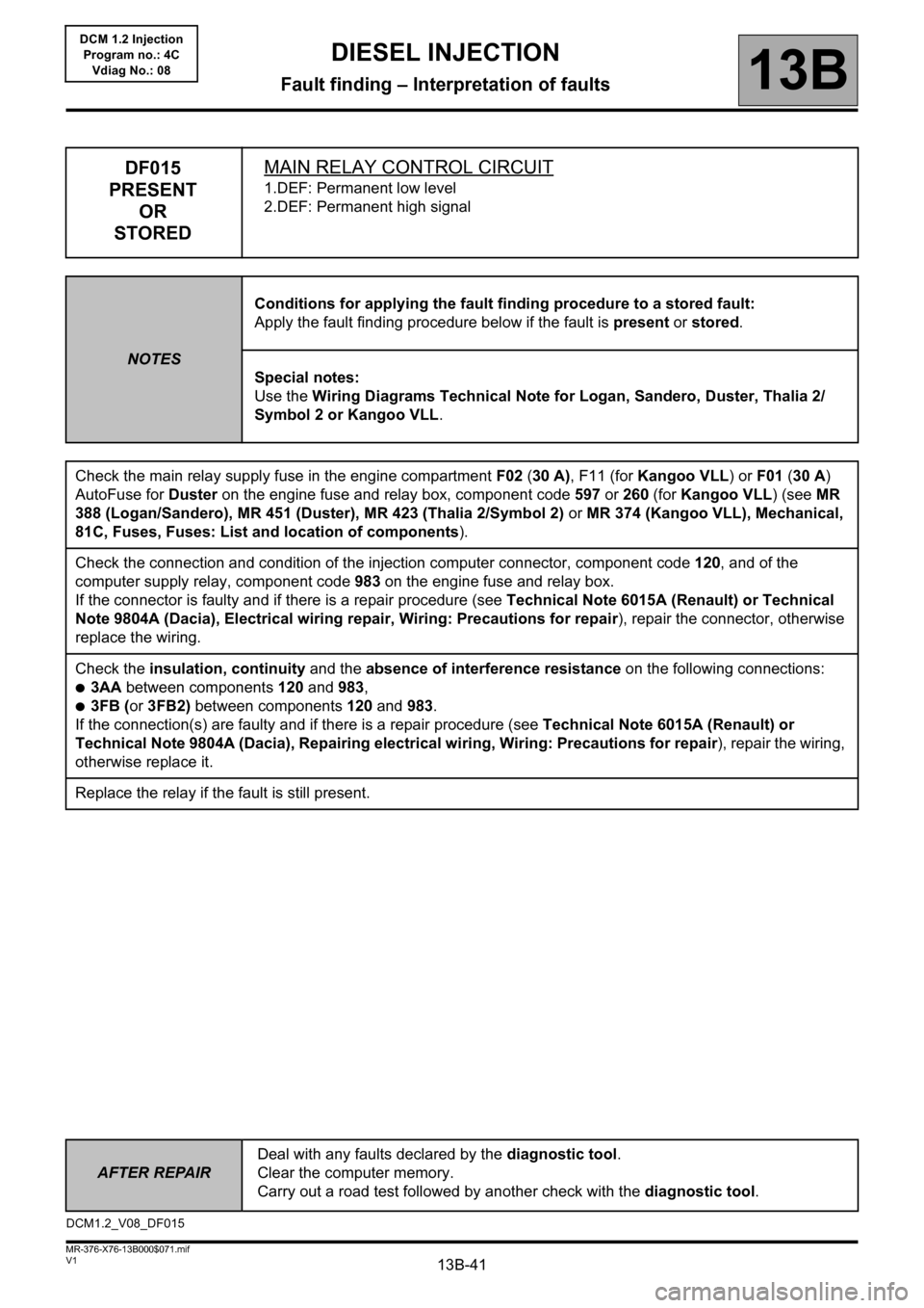
13B-41
AFTER REPAIRDeal with any faults declared by the diagnostic tool.
Clear the computer memory.
Carry out a road test followed by another check with the diagnostic tool.
V1 MR-376-X76-13B000$071.mif
DIESEL INJECTION
Fault finding – Interpretation of faults13B
DCM 1.2 Injection
Program no.: 4C
Vdiag No.: 08
DF015
PRESENT
OR
STOREDMAIN RELAY CONTROL CIRCUIT
1.DEF: Permanent low level
2.DEF: Permanent high signal
NOTESConditions for applying the fault finding procedure to a stored fault:
Apply the fault finding procedure below if the fault is present or stored.
Special notes:
Use the Wiring Diagrams Technical Note for Logan, Sandero, Duster, Thalia 2/
Symbol 2 or Kangoo VLL.
Check the main relay supply fuse in the engine compartment F02 (30 A), F11 (for Kangoo VLL) or F01 (30 A)
AutoFuse for Duster on the engine fuse and relay box, component code 597 or 260 (for Kangoo VLL) (see MR
388 (Logan/Sandero), MR 451 (Duster), MR 423 (Thalia 2/Symbol 2) or MR 374 (Kangoo VLL), Mechanical,
81C, Fuses, Fuses: List and location of components).
Check the connection and condition of the injection computer connector, component code 120, and of the
computer supply relay, component code 983 on the engine fuse and relay box.
If the connector is faulty and if there is a repair procedure (see Technical Note 6015A (Renault) or Technical
Note 9804A (Dacia), Electrical wiring repair, Wiring: Precautions for repair), repair the connector, otherwise
replace the wiring.
Check the insulation, continuity and the absence of interference resistance on the following connections:
●3AA between components 120 and 983,
●3FB (or 3FB2) between components 120 and 983.
If the connection(s) are faulty and if there is a repair procedure (see Technical Note 6015A (Renault) or
Technical Note 9804A (Dacia), Repairing electrical wiring, Wiring: Precautions for repair), repair the wiring,
otherwise replace it.
Replace the relay if the fault is still present.
DCM1.2_V08_DF015
Page 53 of 204
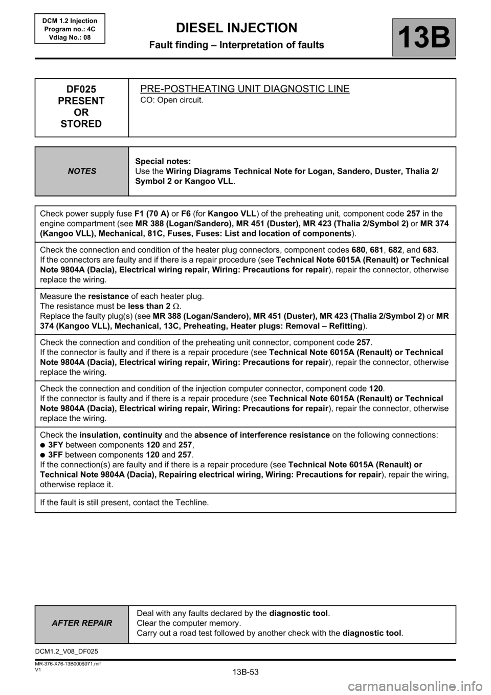
13B-53
AFTER REPAIRDeal with any faults declared by the diagnostic tool.
Clear the computer memory.
Carry out a road test followed by another check with the diagnostic tool.
V1 MR-376-X76-13B000$071.mif
DIESEL INJECTION
Fault finding – Interpretation of faults13B
DCM 1.2 Injection
Program no.: 4C
Vdiag No.: 08
DF025
PRESENT
OR
STOREDPRE-POSTHEATING UNIT DIAGNOSTIC LINE
CO: Open circuit.
NOTESSpecial notes:
Use the Wiring Diagrams Technical Note for Logan, Sandero, Duster, Thalia 2/
Symbol 2 or Kangoo VLL.
Check power supply fuse F1 (70 A) or F6 (for Kangoo VLL) of the preheating unit, component code 257 in the
engine compartment (see MR 388 (Logan/Sandero), MR 451 (Duster), MR 423 (Thalia 2/Symbol 2) or MR 374
(Kangoo VLL), Mechanical, 81C, Fuses, Fuses: List and location of components).
Check the connection and condition of the heater plug connectors, component codes 680, 681, 682, and 683.
If the connectors are faulty and if there is a repair procedure (see Technical Note 6015A (Renault) or Technical
Note 9804A (Dacia), Electrical wiring repair, Wiring: Precautions for repair), repair the connector, otherwise
replace the wiring.
Measure the resistance of each heater plug.
The resistance must be less than 2 .
Replace the faulty plug(s) (see MR 388 (Logan/Sandero), MR 451 (Duster), MR 423 (Thalia 2/Symbol 2) or MR
374 (Kangoo VLL), Mechanical, 13C, Preheating, Heater plugs: Removal – Refitting).
Check the connection and condition of the preheating unit connector, component code 257.
If the connector is faulty and if there is a repair procedure (see Technical Note 6015A (Renault) or Technical
Note 9804A (Dacia), Electrical wiring repair, Wiring: Precautions for repair), repair the connector, otherwise
replace the wiring.
Check the connection and condition of the injection computer connector, component code 120.
If the connector is faulty and if there is a repair procedure (see Technical Note 6015A (Renault) or Technical
Note 9804A (Dacia), Electrical wiring repair, Wiring: Precautions for repair), repair the connector, otherwise
replace the wiring.
Check the insulation, continuity and the absence of interference resistance on the following connections:
●3FY between components120 and 257,
●3FF between components120 and 257.
If the connection(s) are faulty and if there is a repair procedure (see Technical Note 6015A (Renault) or
Technical Note 9804A (Dacia), Repairing electrical wiring, Wiring: Precautions for repair), repair the wiring,
otherwise replace it.
If the fault is still present, contact the Techline.
DCM1.2_V08_DF025
Page 112 of 204
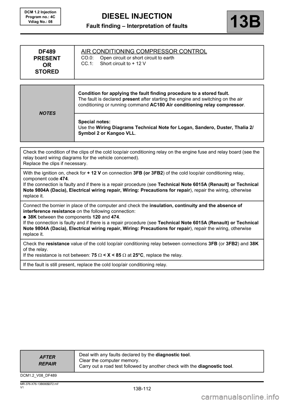
13B-112
AFTER
REPAIRDeal with any faults declared by the diagnostic tool.
Clear the computer memory.
Carry out a road test followed by another check with the diagnostic tool.
V1 MR-376-X76-13B000$072.mif
DIESEL INJECTION
Fault finding – Interpretation of faults13B
DCM 1.2 Injection
Program no.: 4C
Vdiag No.: 08
DF489
PRESENT
OR
STOREDAIR CONDITIONING COMPRESSOR CONTROL
CO.0: Open circuit or short circuit to earth
CC.1: Short circuit to + 12 V
NOTESCondition for applying the fault finding procedure to a stored fault.
The fault is declared present after starting the engine and switching on the air
conditioning or running command AC180 Air conditioning relay compressor.
Special notes:
Use the Wiring Diagrams Technical Note for Logan, Sandero, Duster, Thalia 2/
Symbol 2 or Kangoo VLL.
Check the condition of the clips of the cold loop/air conditioning relay on the engine fuse and relay board (see the
relay board wiring diagrams for the vehicle concerned).
Replace the clips if necessary.
With the ignition on, check for + 12 V on connection 3FB (or 3FB2) of the cold loop/air conditioning relay,
component code 474.
If the connection is faulty and if there is a repair procedure (see Technical Note 6015A (Renault) or Technical
Note 9804A (Dacia), Electrical wiring repair, Wiring: Precautions for repair), repair the wiring, otherwise
replace it.
Connect the bornier in place of the computer and check the insulation, continuity and the absence of
interference resistance on the following connection:
●38K between the components 120 and 474.
If the connection is faulty and if there is a repair procedure (see Technical Note 6015A (Renault) or Technical
Note 9804A (Dacia), Electrical wiring repair, Wiring: Precautions for repair), repair the wiring, otherwise
replace it.
Check the resistance value of the cold loop/air conditioning relay between connections 3FB (or 3FB2) and 38K
of the relay.
If the resistance is not between: 75 < X < 85 at 25°C, replace the relay.
If the fault is still present, replace the cold loop/air conditioning relay.
DCM1.2_V08_DF489
Page 136 of 204
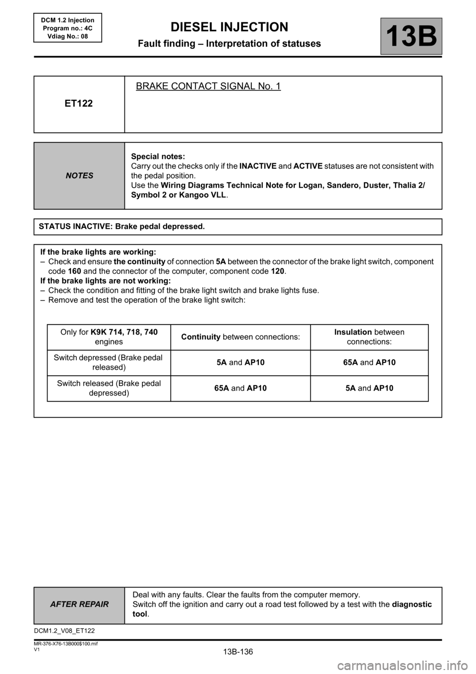
13B-136
AFTER REPAIRDeal with any faults. Clear the faults from the computer memory.
Switch off the ignition and carry out a road test followed by a test with the diagnostic
tool.
V1 MR-376-X76-13B000$100.mif
13B
DCM 1.2 Injection
Program no.: 4C
Vdiag No.: 08
ET122BRAKE CONTACT SIGNAL No. 1
NOTESSpecial notes:
Carry out the checks only if the INACTIVE and ACTIVE statuses are not consistent with
the pedal position.
Use the Wiring Diagrams Technical Note for Logan, Sandero, Duster, Thalia 2/
Symbol 2 or Kangoo VLL.
STATUS INACTIVE: Brake pedal depressed.
If the brake lights are working:
– Check and ensure the continuity of connection 5A between the connector of the brake light switch, component
code 160 and the connector of the computer, component code 120.
If the brake lights are not working:
– Check the condition and fitting of the brake light switch and brake lights fuse.
– Remove and test the operation of the brake light switch:
Only for K9K 714, 718, 740
enginesContinuity between connections:Insulation between
connections:
Switch depressed (Brake pedal
released)5A and AP10 65A and AP10
Switch released (Brake pedal
depressed)65A and AP10 5A and AP10
DCM1.2_V08_ET122
DIESEL INJECTION
Fault finding – Interpretation of statuses
Page 188 of 204
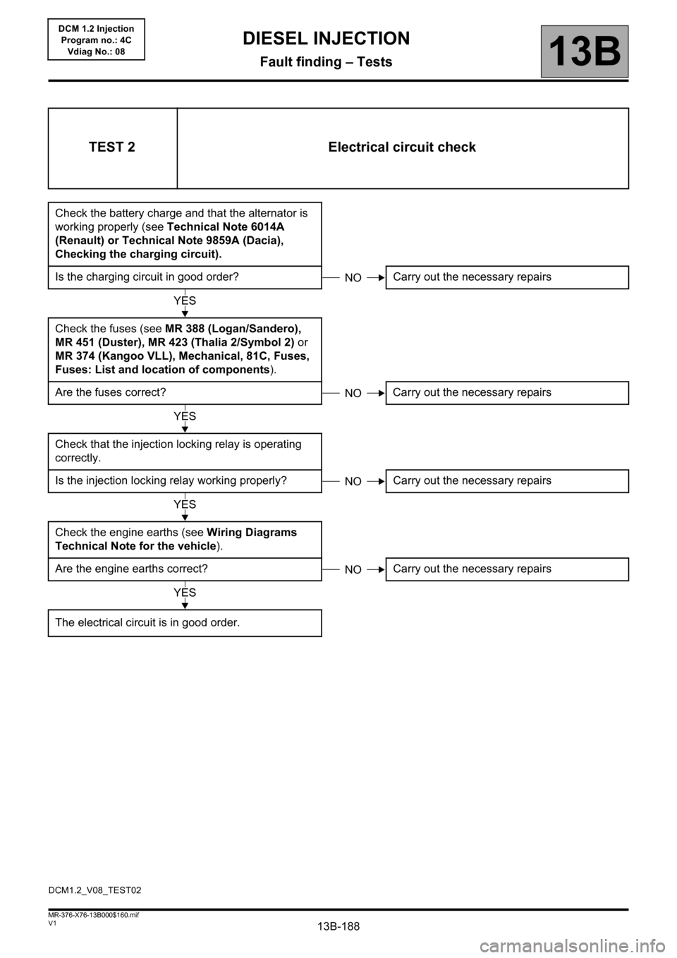
13B-188V1 MR-376-X76-13B000$160.mif
DIESEL INJECTION
Fault finding – Tests13B
DCM 1.2 Injection
Program no.: 4C
Vdiag No.: 08
TEST 2 Electrical circuit check
Check the battery charge and that the alternator is
working properly (see Technical Note 6014A
(Renault) or Technical Note 9859A (Dacia),
Checking the charging circuit).
Is the charging circuit in good order? Carry out the necessary repairs
Check the fuses (see MR 388 (Logan/Sandero),
MR 451 (Duster), MR 423 (Thalia 2/Symbol 2) or
MR 374 (Kangoo VLL), Mechanical, 81C, Fuses,
Fuses: List and location of components).
Are the fuses correct? Carry out the necessary repairs
Check that the injection locking relay is operating
correctly.
Is the injection locking relay working properly? Carry out the necessary repairs
Check the engine earths (see Wiring Diagrams
Technical Note for the vehicle).
Are the engine earths correct? Carry out the necessary repairs
The electrical circuit is in good order.
NO
YES
NO
YES
NO
YES
NO
YES
DCM1.2_V08_TEST02