RENAULT KANGOO 2013 X61 / 2.G Lighting Owner's Manual
Manufacturer: RENAULT, Model Year: 2013, Model line: KANGOO, Model: RENAULT KANGOO 2013 X61 / 2.GPages: 30, PDF Size: 0.24 MB
Page 21 of 30
80D-21
AFTER REPAIRCarry out a road test and then a check using the diagnostic tool.
V1 MR-376-X76-80D000$100.mif
80D
UCH
Vdiag No.: 0F
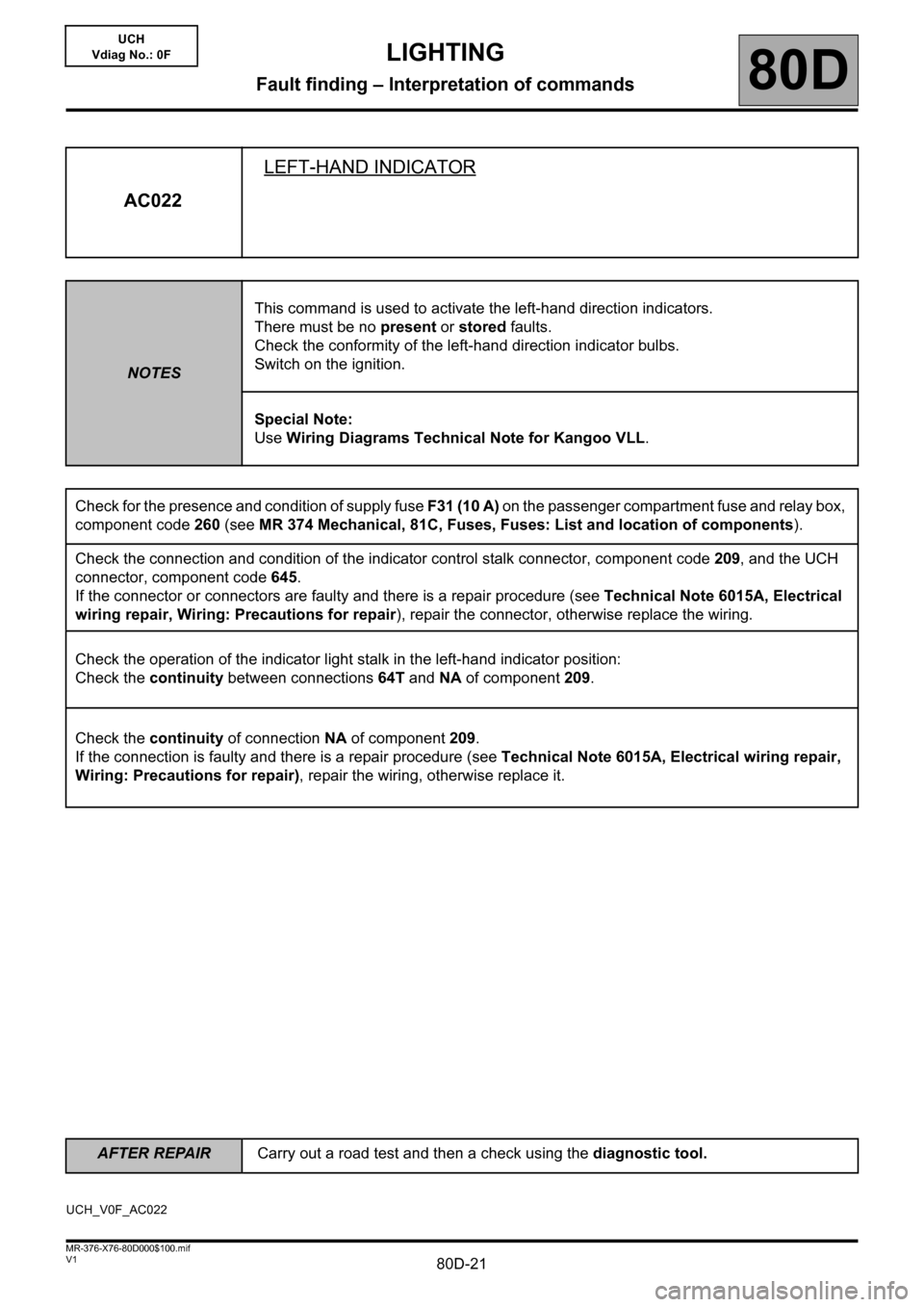
AC022LEFT-HAND INDICATOR
NOTESThis command is used to activate the left-hand direction indicators.
There must be no present or stored faults.
Check the conformity of the left-hand direction indicator bulbs.
Switch on the ignition.
Special Note:
Use Wiring Diagrams Technical Note for Kangoo VLL.
Check for the presence and condition of supply fuse F31 (10 A) on the passenger compartment fuse and relay box,
component code 260 (see MR 374 Mechanical, 81C, Fuses, Fuses: List and location of components).
Check the connection and condition of the indicator control stalk connector, component code 209, and the UCH
connector, component code 645.
If the connector or connectors are faulty and there is a repair procedure (see Technical Note 6015A, Electrical
wiring repair, Wiring: Precautions for repair), repair the connector, otherwise replace the wiring.
Check the operation of the indicator light stalk in the left-hand indicator position:
Check the continuity between connections 64T and NA of component 209.
Check the continuity of connection NA of component 209.
If the connection is faulty and there is a repair procedure (see Technical Note 6015A, Electrical wiring repair,
Wiring: Precautions for repair), repair the wiring, otherwise replace it.
UCH_V0F_AC022
LIGHTING
Fault finding – Interpretation of commands
Page 22 of 30
80D-22
AFTER REPAIRCarry out a road test and then a check using the diagnostic tool.
V1 MR-376-X76-80D000$100.mif
LIGHTING
Fault finding – Interpretation of commands80D
UCH
Vdiag No.: 0F
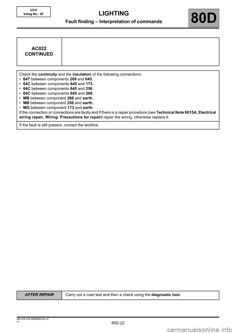
AC022
CONTINUED
Check the continuity and the insulation of the following connections:
•64T between components 209 and 645,
•64C between components 645 and 173,
•64C between components 645 and 256,
•64C between components 645 and 268,
•MB between component 268 and earth,
•MB between component 256 and earth,
•MG between component 173 and earth.
If the connection or connections are faulty and if there is a repair procedure (see Technical Note 6015A, Electrical
wiring repair, Wiring: Precautions for repair) repair the wiring, otherwise replace it.
If the fault is still present, contact the techline.
Page 23 of 30
80D-23
AFTER REPAIRCarry out a road test and then a check using the diagnostic tool.
V1 MR-376-X76-80D000$100.mif
LIGHTING
Fault finding – Interpretation of commands80D
UCH
Vdiag No.: 0F
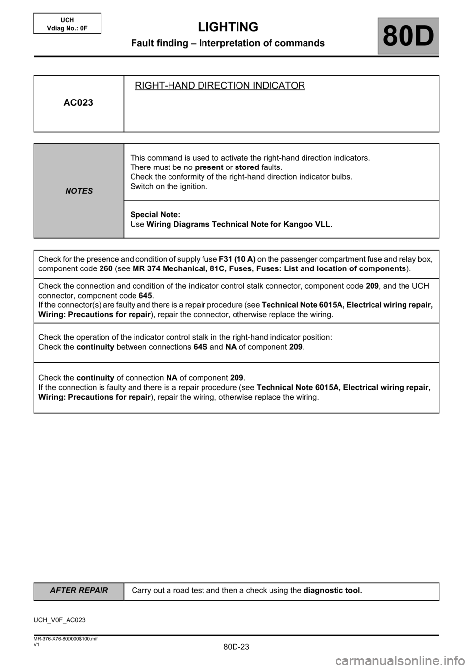
AC023RIGHT-HAND DIRECTION INDICATOR
NOTESThis command is used to activate the right-hand direction indicators.
There must be no present or stored faults.
Check the conformity of the right-hand direction indicator bulbs.
Switch on the ignition.
Special Note:
Use Wiring Diagrams Technical Note for Kangoo VLL.
Check for the presence and condition of supply fuse F31 (10 A) on the passenger compartment fuse and relay box,
component code 260 (see MR 374 Mechanical, 81C, Fuses, Fuses: List and location of components).
Check the connection and condition of the indicator control stalk connector, component code 209, and the UCH
connector, component code 645.
If the connector(s) are faulty and there is a repair procedure (see Technical Note 6015A, Electrical wiring repair,
Wiring: Precautions for repair), repair the connector, otherwise replace the wiring.
Check the operation of the indicator control stalk in the right-hand indicator position:
Check the continuity between connections 64S and NA of component 209.
Check the continuity of connection NA of component 209.
If the connection is faulty and there is a repair procedure (see Technical Note 6015A, Electrical wiring repair,
Wiring: Precautions for repair), repair the wiring, otherwise replace the wiring.
UCH_V0F_AC023
Page 24 of 30
80D-24
AFTER REPAIRCarry out a road test and then a check using the diagnostic tool.
V1 MR-376-X76-80D000$100.mif
LIGHTING
Fault finding – Interpretation of commands80D
UCH
Vdiag No.: 0F
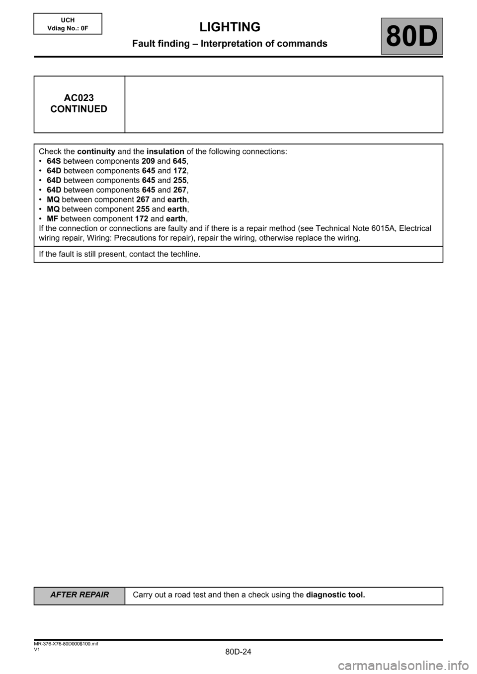
AC023
CONTINUED
Check the continuity and the insulation of the following connections:
•64S between components 209 and 645,
•64D between components 645 and 172,
•64D between components 645 and 255,
•64D between components 645 and 267,
•MQ between component 267 and earth,
•MQ between component 255 and earth,
•MF between component 172 and earth,
If the connection or connections are faulty and if there is a repair method (see Technical Note 6015A, Electrical
wiring repair, Wiring: Precautions for repair), repair the wiring, otherwise replace the wiring.
If the fault is still present, contact the techline.
Page 25 of 30
80D-25
AFTER REPAIRCarry out a road test and then a check using the diagnostic tool.
V1 MR-376-X76-80D000$100.mif
LIGHTING
Fault finding – Interpretation of commands80D
UCH
Vdiag No.: 0F
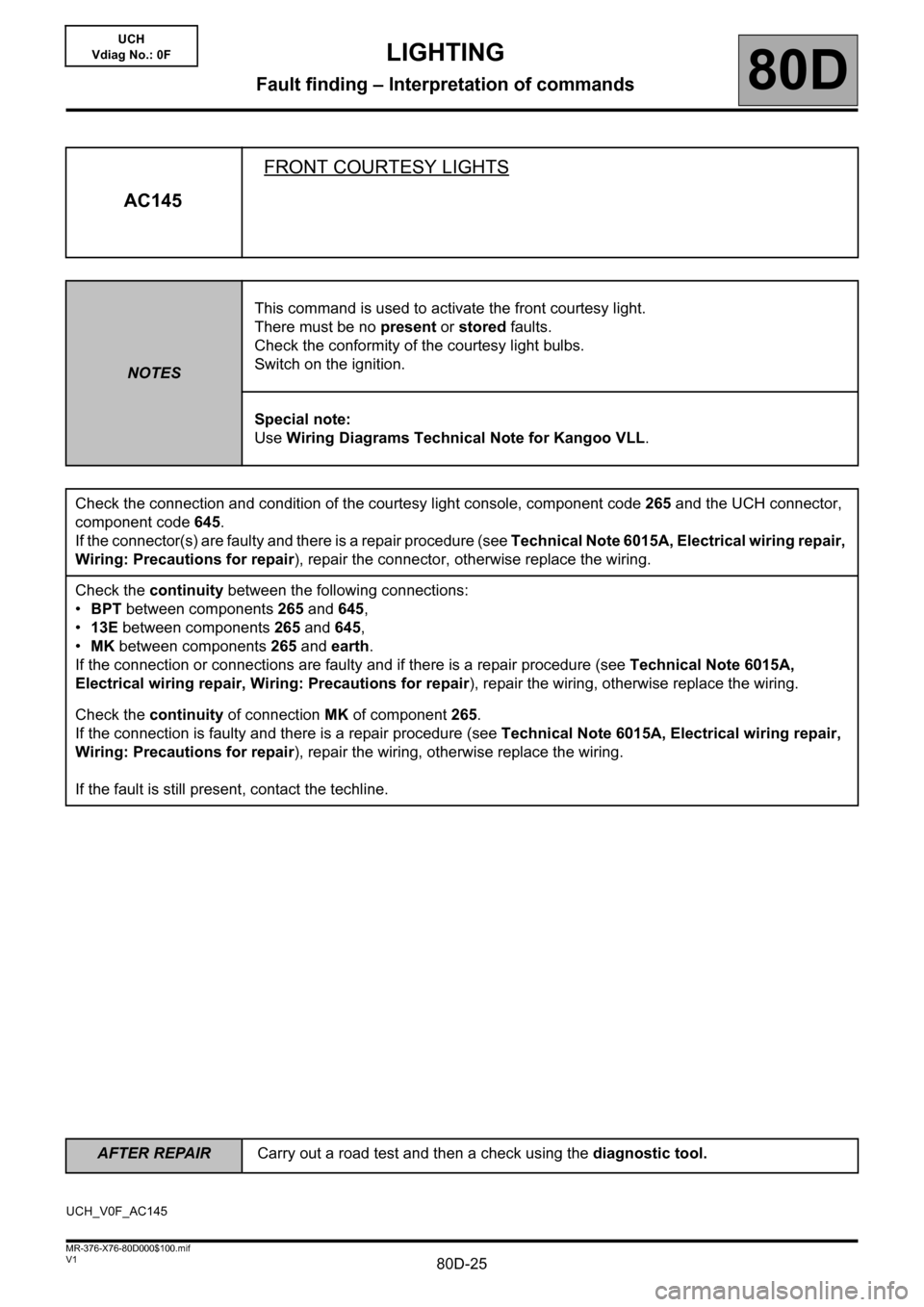
AC145FRONT COURTESY LIGHTS
NOTESThis command is used to activate the front courtesy light.
There must be no present or stored faults.
Check the conformity of the courtesy light bulbs.
Switch on the ignition.
Special note:
Use Wiring Diagrams Technical Note for Kangoo VLL.
Check the connection and condition of the courtesy light console, component code 265 and the UCH connector,
component code 645.
If the connector(s) are faulty and there is a repair procedure (see Technical Note 6015A, Electrical wiring repair,
Wiring: Precautions for repair), repair the connector, otherwise replace the wiring.
Check the continuity between the following connections:
•BPT between components 265 and 645,
•13E between components 265 and 645,
•MK between components 265 and earth.
If the connection or connections are faulty and if there is a repair procedure (see Technical Note 6015A,
Electrical wiring repair, Wiring: Precautions for repair), repair the wiring, otherwise replace the wiring.
Check the continuity of connection MK of component 265.
If the connection is faulty and there is a repair procedure (see Technical Note 6015A, Electrical wiring repair,
Wiring: Precautions for repair), repair the wiring, otherwise replace the wiring.
If the fault is still present, contact the techline.
UCH_V0F_AC145
Page 26 of 30
80D-26V1 MR-376-X76-80D000$110.mif
80D
UCH
Vdiag No.: 0F
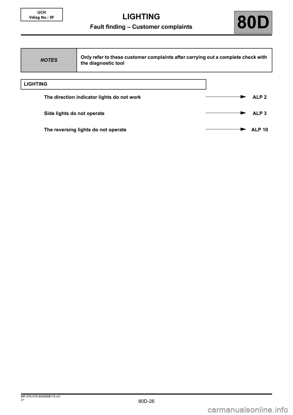
NOTESOnly refer to these customer complaints after carrying out a complete check with
the diagnostic tool
LIGHTING
The direction indicator lights do not work ALP 2
Side lights do not operate ALP 3
The reversing lights do not operate ALP 10
LIGHTING
Fault finding – Customer complaints
Page 27 of 30
80D-27
AFTER REPAIRCheck the system operation.
V1 MR-376-X76-80D000$120.mif
80D
UCH
Vdiag No.: 0F
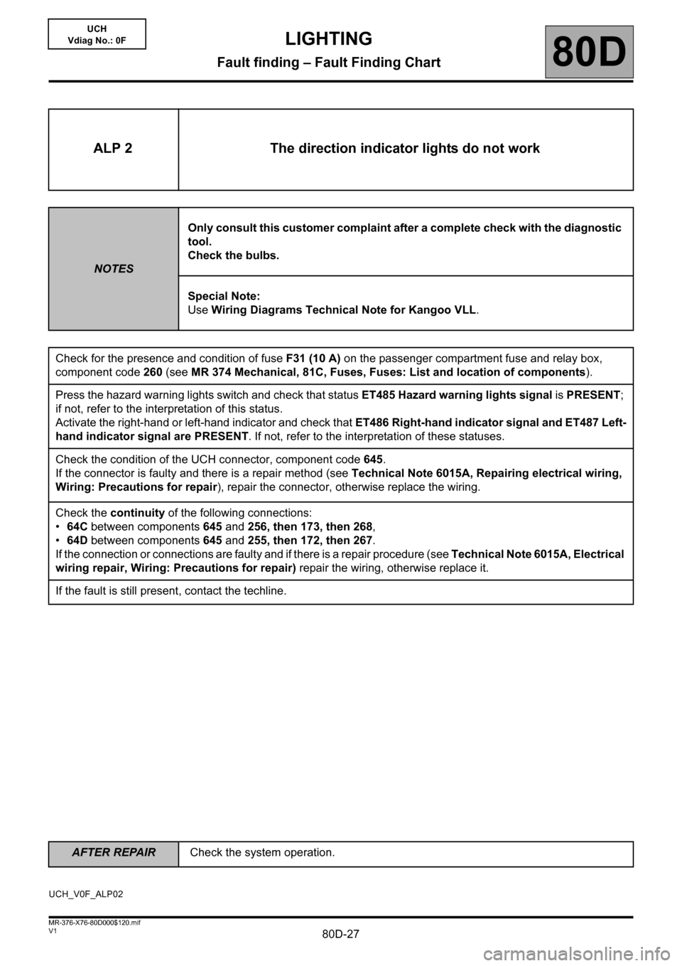
ALP 2 The direction indicator lights do not work
NOTESOnly consult this customer complaint after a complete check with the diagnostic
tool.
Check the bulbs.
Special Note:
Use Wiring Diagrams Technical Note for Kangoo VLL.
Check for the presence and condition of fuse F31 (10 A) on the passenger compartment fuse and relay box,
component code 260 (see MR 374 Mechanical, 81C, Fuses, Fuses: List and location of components).
Press the hazard warning lights switch and check that status ET485 Hazard warning lights signal is PRESENT;
if not, refer to the interpretation of this status.
Activate the right-hand or left-hand indicator and check that ET486 Right-hand indicator signal and ET487 Left-
hand indicator signal are PRESENT. If not, refer to the interpretation of these statuses.
Check the condition of the UCH connector, component code 645.
If the connector is faulty and there is a repair method (see Technical Note 6015A, Repairing electrical wiring,
Wiring: Precautions for repair), repair the connector, otherwise replace the wiring.
Check the continuity of the following connections:
•64C between components 645 and 256, then 173, then 268,
•64D between components 645 and 255, then 172, then 267.
If the connection or connections are faulty and if there is a repair procedure (see Technical Note 6015A, Electrical
wiring repair, Wiring: Precautions for repair) repair the wiring, otherwise replace it.
If the fault is still present, contact the techline.
UCH_V0F_ALP02
LIGHTING
Fault finding – Fault Finding Chart
Page 28 of 30
80D-28
AFTER REPAIRCheck the system operation.
V1 MR-376-X76-80D000$120.mif
LIGHTING
Fault finding – Fault Finding Chart80D
UCH
Vdiag No.: 0F
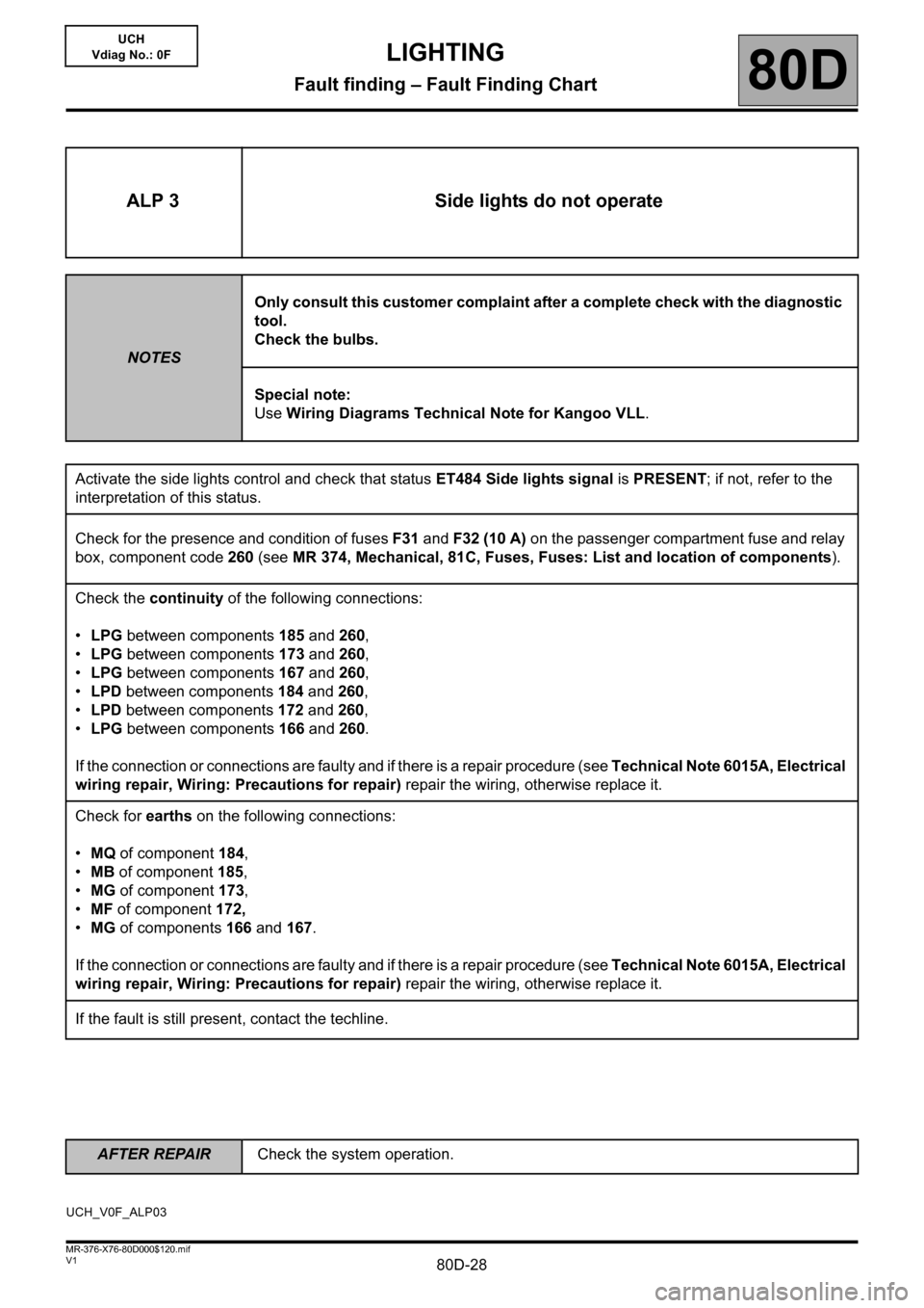
ALP 3 Side lights do not operate
NOTESOnly consult this customer complaint after a complete check with the diagnostic
tool.
Check the bulbs.
Special note:
Use Wiring Diagrams Technical Note for Kangoo VLL.
Activate the side lights control and check that status ET484 Side lights signal is PRESENT; if not, refer to the
interpretation of this status.
Check for the presence and condition of fuses F31 and F32 (10 A) on the passenger compartment fuse and relay
box, component code 260 (see MR 374, Mechanical, 81C, Fuses, Fuses: List and location of components).
Check the continuity of the following connections:
•LPG between components 185 and 260,
•LPG between components 173 and 260,
•LPG between components 167 and 260,
•LPD between components 184 and 260,
•LPD between components 172 and 260,
•LPG between components166 and 260.
If the connection or connections are faulty and if there is a repair procedure (see Technical Note 6015A, Electrical
wiring repair, Wiring: Precautions for repair) repair the wiring, otherwise replace it.
Check for earths on the following connections:
•MQ of component 184,
•MB of component 185,
•MG of component 173,
•MF of component 172,
•MG of components 166 and 167.
If the connection or connections are faulty and if there is a repair procedure (see Technical Note 6015A, Electrical
wiring repair, Wiring: Precautions for repair) repair the wiring, otherwise replace it.
If the fault is still present, contact the techline.
UCH_V0F_ALP03
Page 29 of 30

80D-29
AFTER REPAIRCarry out a check using the diagnostic tool.
V1 MR-376-X76-80D000$120.mif
LIGHTING
Fault finding – Fault Finding Chart80D
UCH
Vdiag No.: 0F
ALP 10 The reversing lights do not operate
Check for the presence and condition of fuse
F14 (15 A) in the passenger compartment fuse
and relay box, component code 260.
Is the result of the check correct? Replace the fuse if necessary (see MR
374, Mechanical, 81C, Fuses, Fuses:
List and location of components).
Check the bulbs and condition of the bulb
supports.
Are the checks correct?Replace the bulbs if necessary (see MR
374 Mechanical, 81A, Rear lighting,
Rear light bulb: Removal - Refitting).
Check the condition and connection of the
connectors of components 155 and 172.
Are the checks correct?If the connector or connectors are faulty
and there is a repair procedure (see
Technical Note 6015A, Electrical
wiring repair, Wiring: Precautions for
repair), repair the connector, otherwise
replace the wiring.
Check for earth on the following connections:
–MF between component 172 and earth.
Is it correct?If the connection or connections are faulty
and there is a repair procedure (see
Technical Note 6015A, Electrical
wiring repair, Wiring: Precautions for
repair), repair the wiring, otherwise
replace it.
NO
YES
NO
YES
NO
YES
NO
YES
A
UCH_V0F_ALP10
Page 30 of 30
80D-30
AFTER REPAIRCarry out a check using the diagnostic tool.
V1 MR-376-X76-80D000$120.mif
LIGHTING
Fault finding – Fault Finding Chart80D
UCH
Vdiag No.: 0F
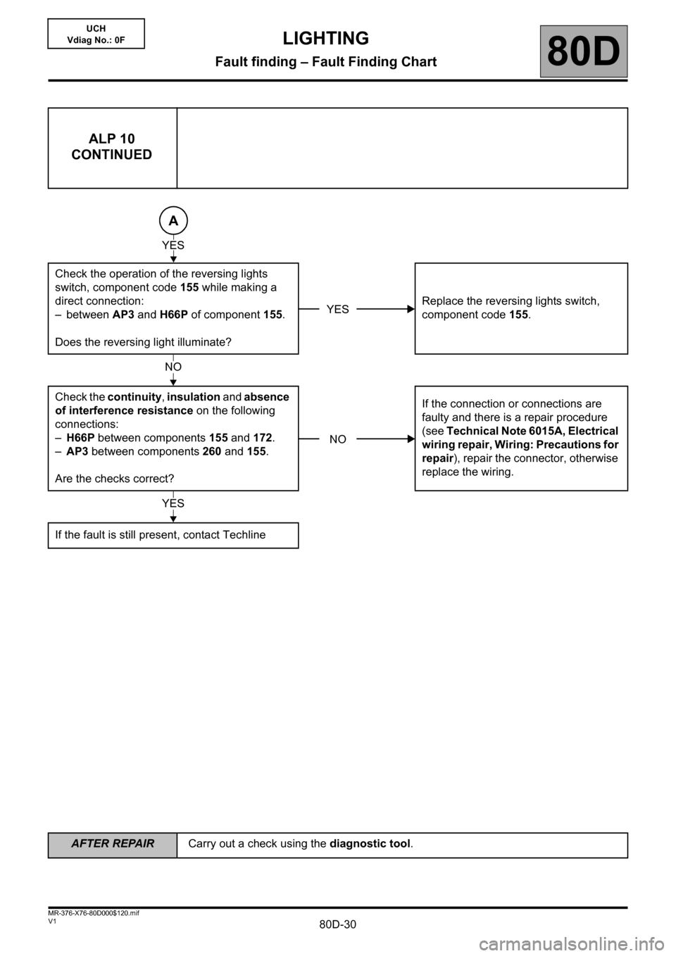
ALP 10
CONTINUED
Check the operation of the reversing lights
switch, component code 155 while making a
direct connection:
– between AP3 and H66P of component 155.
Does the reversing light illuminate?Replace the reversing lights switch,
component code 155.
Check the continuity, insulation and absence
of interference resistance on the following
connections:
–H66P between components 155 and 172.
–AP3 between components 260 and 155.
Are the checks correct?If the connection or connections are
faulty and there is a repair procedure
(see Technical Note 6015A, Electrical
wiring repair, Wiring: Precautions for
repair), repair the connector, otherwise
replace the wiring.
If the fault is still present, contact Techline
A
YES
YES
NO
NO
YES