RENAULT KANGOO 2013 X61 / 2.G Lighting User Guide
Manufacturer: RENAULT, Model Year: 2013, Model line: KANGOO, Model: RENAULT KANGOO 2013 X61 / 2.GPages: 30, PDF Size: 0.24 MB
Page 11 of 30
80D-11V1 MR-376-X76-80D000$040.mif
80D
UCH
Vdiag No.: 0F
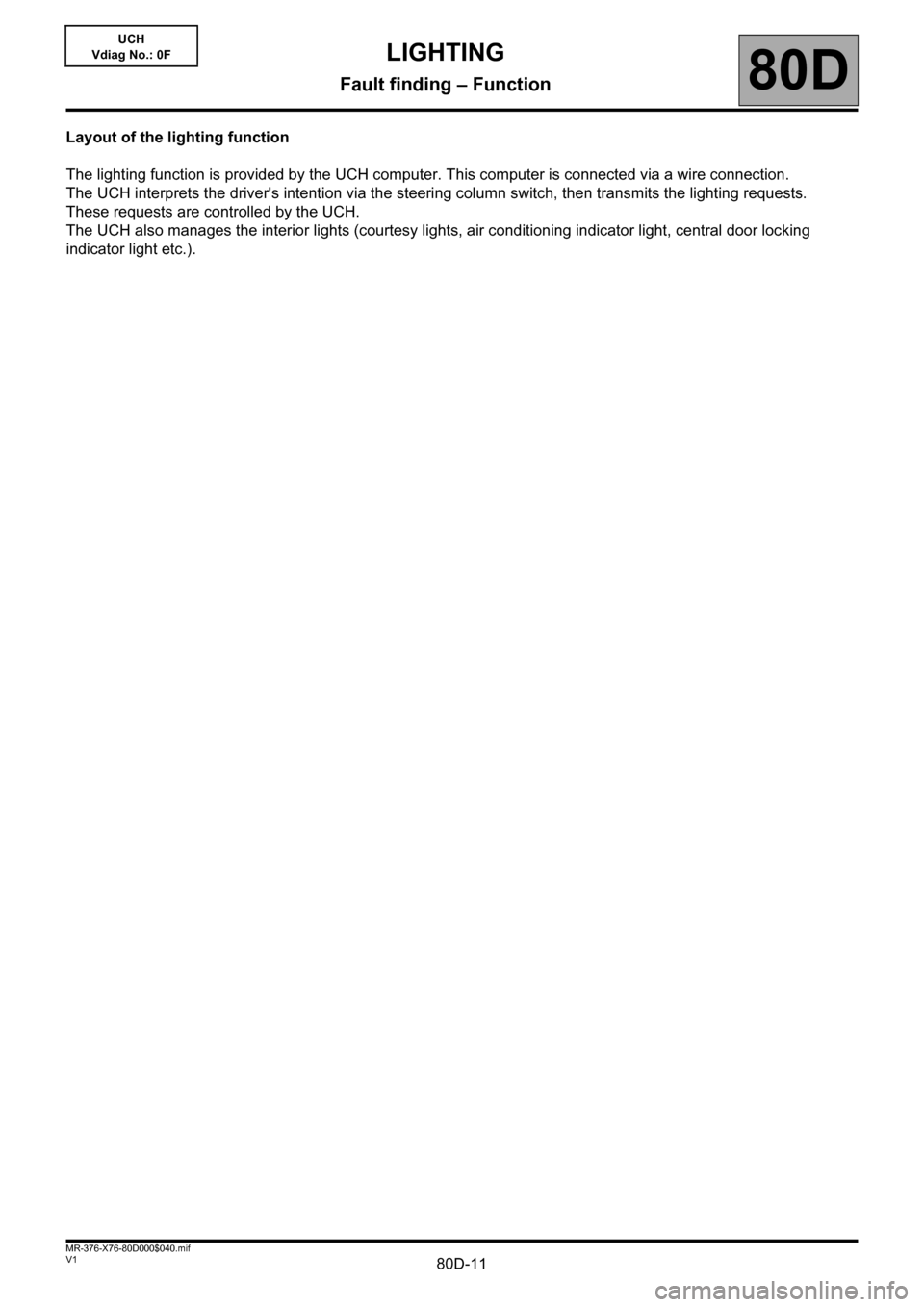
Layout of the lighting function
The lighting function is provided by the UCH computer. This computer is connected via a wire connection.
The UCH interprets the driver's intention via the steering column switch, then transmits the lighting requests.
These requests are controlled by the UCH.
The UCH also manages the interior lights (courtesy lights, air conditioning indicator light, central door locking
indicator light etc.).
LIGHTING
Fault finding – Function
Page 12 of 30
80D-12V1 MR-376-X76-80D000$040.mif
LIGHTING
Fault finding – Function80D
UCH
Vdiag No.: 0F
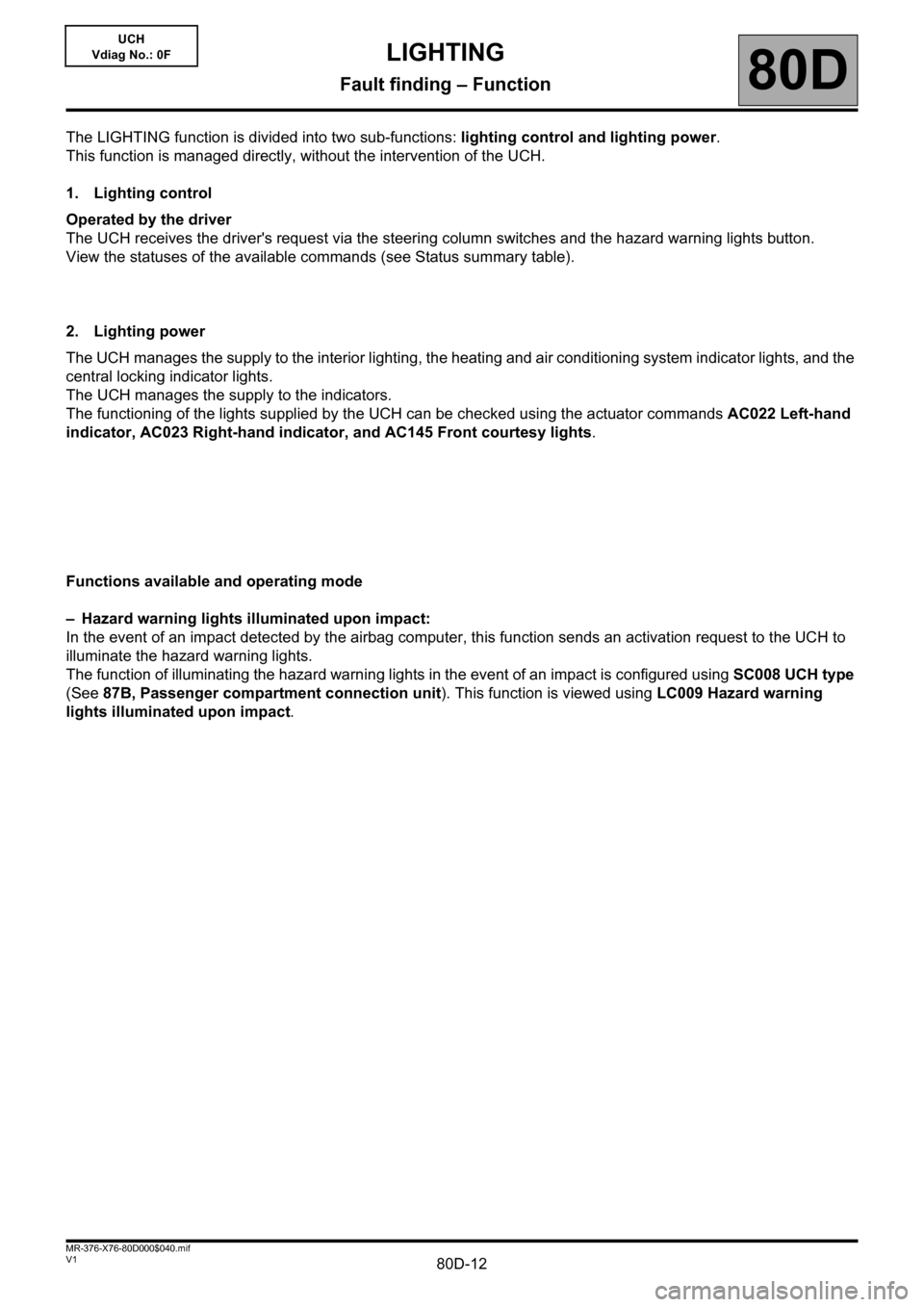
The LIGHTING function is divided into two sub-functions: lighting control and lighting power.
This function is managed directly, without the intervention of the UCH.
1. Lighting control
Operated by the driver
The UCH receives the driver's request via the steering column switches and the hazard warning lights button.
View the statuses of the available commands (see Status summary table).
2. Lighting power
The UCH manages the supply to the interior lighting, the heating and air conditioning system indicator lights, and the
central locking indicator lights.
The UCH manages the supply to the indicators.
The functioning of the lights supplied by the UCH can be checked using the actuator commands AC022 Left-hand
indicator, AC023 Right-hand indicator, and AC145 Front courtesy lights.
Functions available and operating mode
– Hazard warning lights illuminated upon impact:
In the event of an impact detected by the airbag computer, this function sends an activation request to the UCH to
illuminate the hazard warning lights.
The function of illuminating the hazard warning lights in the event of an impact is configured using SC008 UCH type
(See 87B, Passenger compartment connection unit). This function is viewed using LC009 Hazard warning
lights illuminated upon impact.
Page 13 of 30
80D-13V1 MR-376-X76-80D000$050.mif
80D
UCH
Vdiag No.: 0F
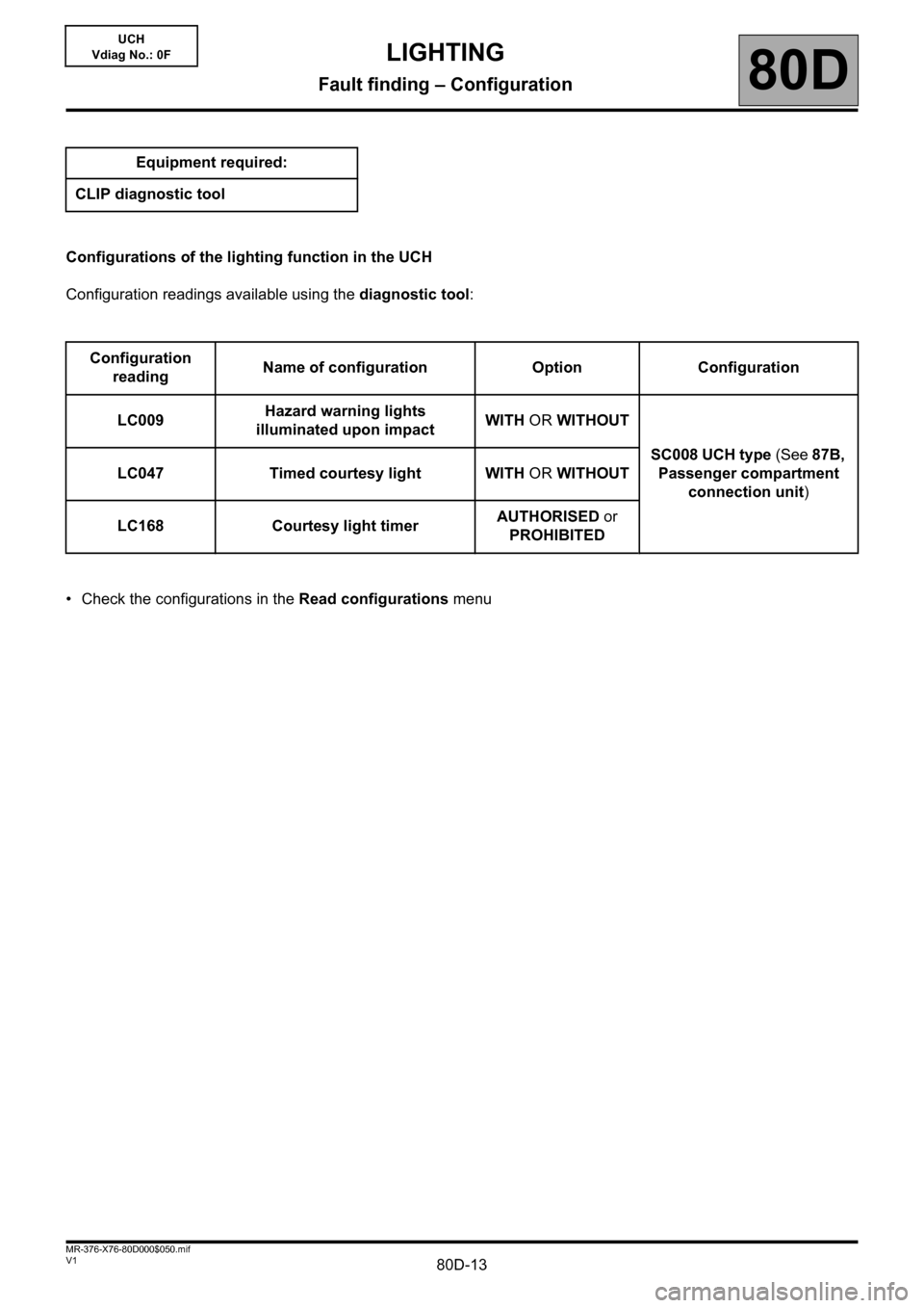
Configurations of the lighting function in the UCH
Configuration readings available using the diagnostic tool:
• Check the configurations in the Read configurations menu Equipment required:
CLIP diagnostic tool
Configuration
readingName of configuration Option Configuration
LC009Hazard warning lights
illuminated upon impactWITH OR WITHOUT
SC008 UCH type (See 87B,
Passenger compartment
connection unit) LC047 Timed courtesy light WITH OR WITHOUT
LC168 Courtesy light timerAUTHORISED or
PROHIBITED
LIGHTING
Fault finding – Configuration
Page 14 of 30
80D-14V1 MR-376-X76-80D000$060.mif
80D
UCH
Vdiag No.: 0F
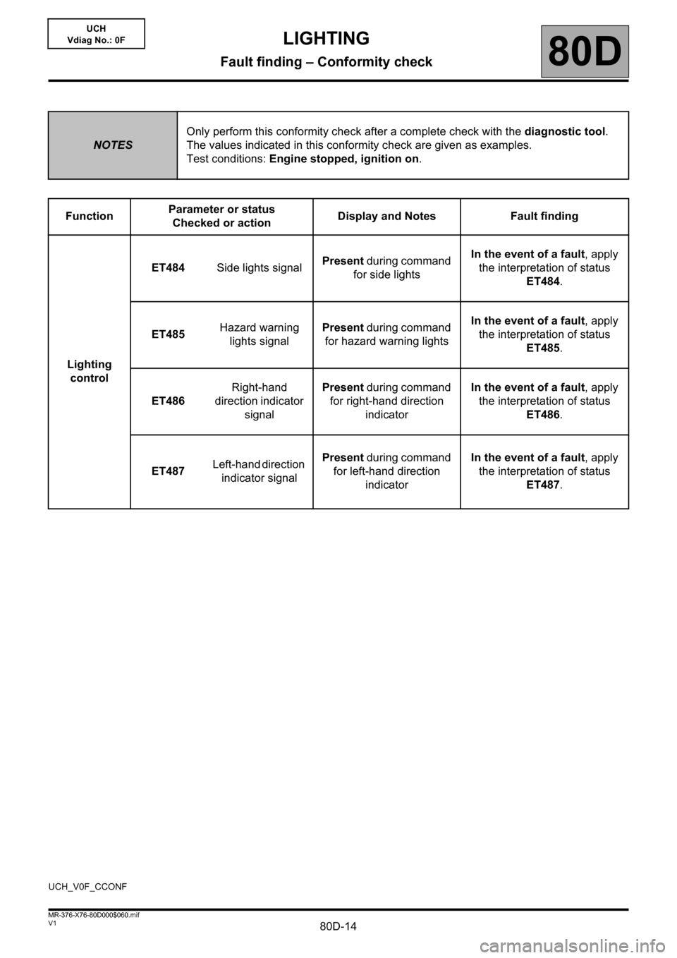
NOTESOnly perform this conformity check after a complete check with the diagnostic tool.
The values indicated in this conformity check are given as examples.
Test conditions: Engine stopped, ignition on.
FunctionParameter or status
Checked or actionDisplay and Notes Fault finding
Lighting
controlET484Side lights signalPresent during command
for side lights In the event of a fault, apply
the interpretation of status
ET484.
ET485Hazard warning
lights signalPresent during command
for hazard warning lightsIn the event of a fault, apply
the interpretation of status
ET485.
ET486Right-hand
direction indicator
signalPresent during command
for right-hand direction
indicatorIn the event of a fault, apply
the interpretation of status
ET486.
ET487Left-hand direction
indicator signalPresent during command
for left-hand direction
indicatorIn the event of a fault, apply
the interpretation of status
ET487.
UCH_V0F_CCONF
LIGHTING
Fault finding – Conformity check
Page 15 of 30
80D-15V1 MR-376-X76-80D000$070.mif
80D
UCH
Vdiag No.: 0F
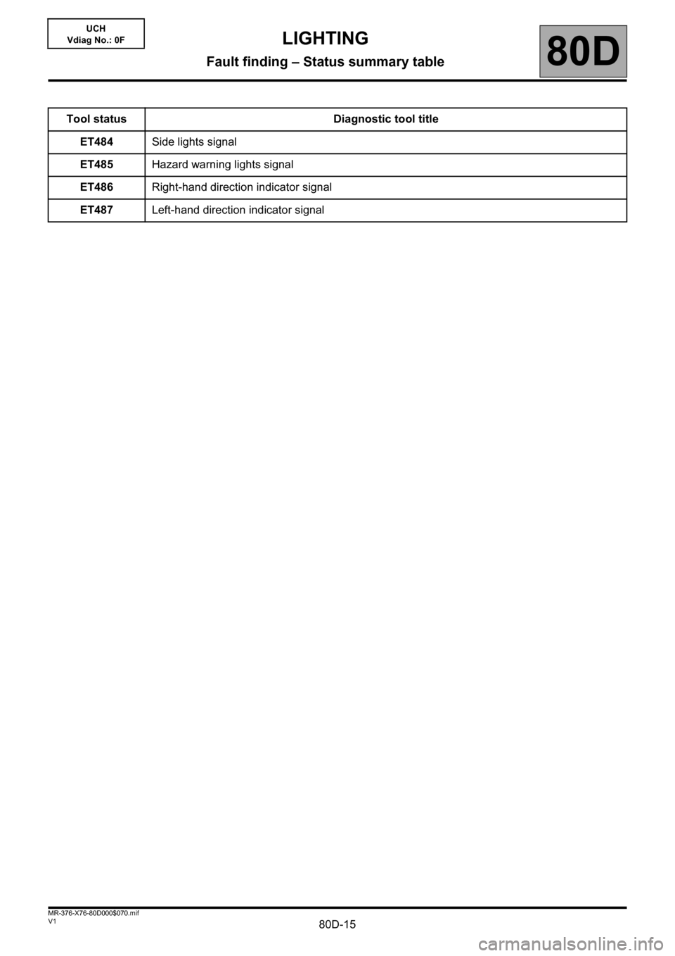
Tool status Diagnostic tool title
ET484Side lights signal
ET485Hazard warning lights signal
ET486Right-hand direction indicator signal
ET487Left-hand direction indicator signal
LIGHTING
Fault finding – Status summary table
Page 16 of 30
80D-16
AFTER REPAIRCarry out another fault finding check on the system.
Deal with any other faults.
Clear the stored faults.
V1 MR-376-X76-80D000$080.mif
80D
UCH
Vdiag No.: 0F
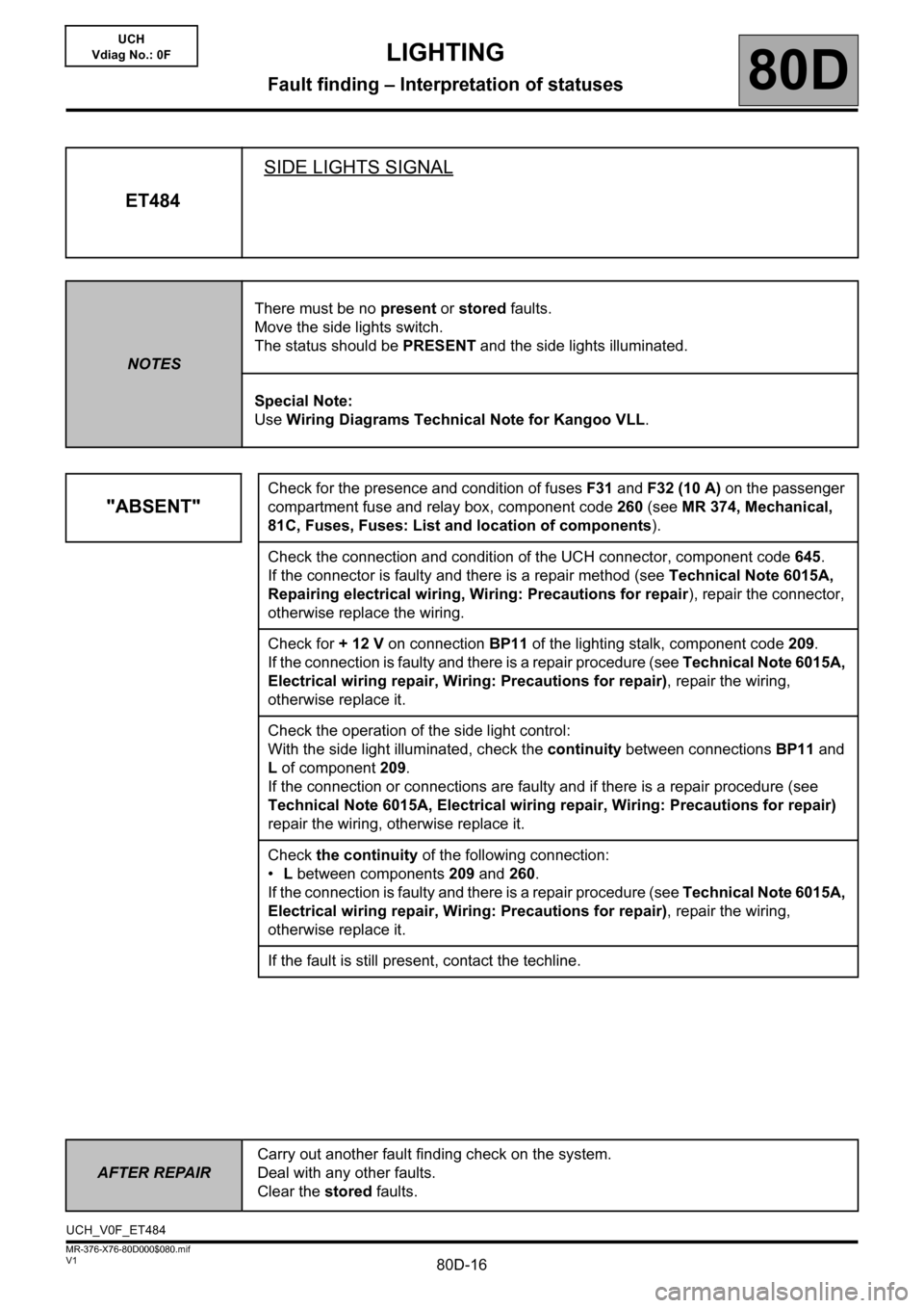
ET484SIDE LIGHTS SIGNAL
NOTESThere must be no present or stored faults.
Move the side lights switch.
The status should be PRESENT and the side lights illuminated.
Special Note:
Use Wiring Diagrams Technical Note for Kangoo VLL.
"ABSENT"
Check for the presence and condition of fuses F31 and F32 (10 A) on the passenger
compartment fuse and relay box, component code 260 (see MR 374, Mechanical,
81C, Fuses, Fuses: List and location of components).
Check the connection and condition of the UCH connector, component code 645.
If the connector is faulty and there is a repair method (see Technical Note 6015A,
Repairing electrical wiring, Wiring: Precautions for repair), repair the connector,
otherwise replace the wiring.
Check for + 12 V on connection BP11 of the lighting stalk, component code 209.
If the connection is faulty and there is a repair procedure (see Technical Note 6015A,
Electrical wiring repair, Wiring: Precautions for repair), repair the wiring,
otherwise replace it.
Check the operation of the side light control:
With the side light illuminated, check the continuity between connections BP11 and
L of component 209.
If the connection or connections are faulty and if there is a repair procedure (see
Technical Note 6015A, Electrical wiring repair, Wiring: Precautions for repair)
repair the wiring, otherwise replace it.
Check the continuity of the following connection:
•L between components 209 and 260.
If the connection is faulty and there is a repair procedure (see Technical Note 6015A,
Electrical wiring repair, Wiring: Precautions for repair), repair the wiring,
otherwise replace it.
If the fault is still present, contact the techline.
UCH_V0F_ET484
LIGHTING
Fault finding – Interpretation of statuses
Page 17 of 30
80D-17
AFTER REPAIRCarry out another fault finding check on the system.
Deal with any other faults.
Clear the stored faults.
V1 MR-376-X76-80D000$080.mif
LIGHTING
Fault finding – Interpretation of statuses80D
UCH
Vdiag No.: 0F
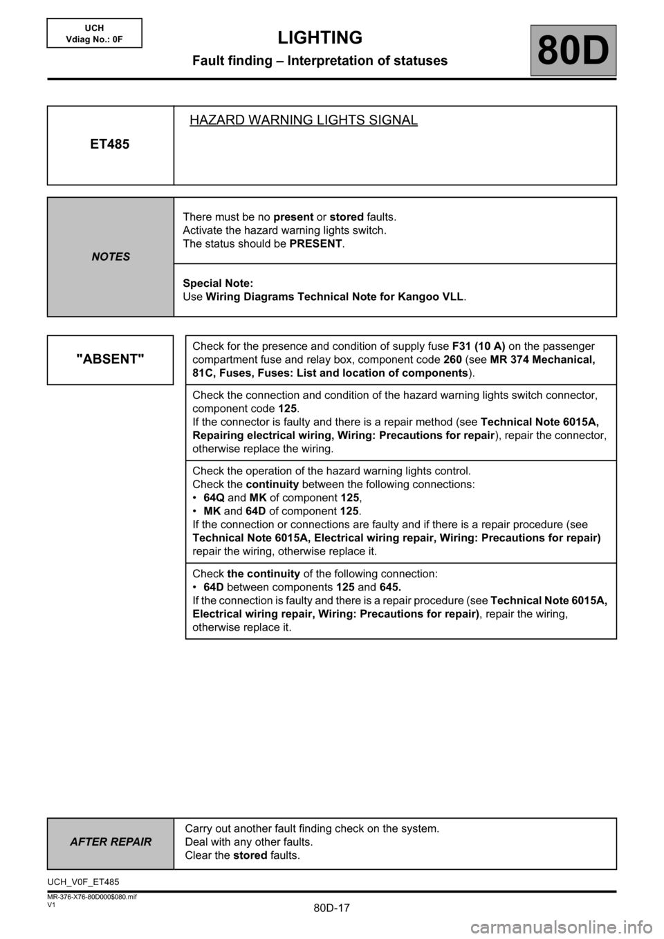
ET485HAZARD WARNING LIGHTS SIGNAL
NOTESThere must be no present or stored faults.
Activate the hazard warning lights switch.
The status should be PRESENT.
Special Note:
Use Wiring Diagrams Technical Note for Kangoo VLL.
"ABSENT"
Check for the presence and condition of supply fuse F31 (10 A) on the passenger
compartment fuse and relay box, component code 260 (see MR 374 Mechanical,
81C, Fuses, Fuses: List and location of components).
Check the connection and condition of the hazard warning lights switch connector,
component code 125.
If the connector is faulty and there is a repair method (see Technical Note 6015A,
Repairing electrical wiring, Wiring: Precautions for repair), repair the connector,
otherwise replace the wiring.
Check the operation of the hazard warning lights control.
Check the continuity between the following connections:
•64Q and MK of component 125,
•MK and 64D of component 125.
If the connection or connections are faulty and if there is a repair procedure (see
Technical Note 6015A, Electrical wiring repair, Wiring: Precautions for repair)
repair the wiring, otherwise replace it.
Check the continuity of the following connection:
•64D between components 125 and 645.
If the connection is faulty and there is a repair procedure (see Technical Note 6015A,
Electrical wiring repair, Wiring: Precautions for repair), repair the wiring,
otherwise replace it.
UCH_V0F_ET485
Page 18 of 30
80D-18
AFTER REPAIRCarry out another fault finding check on the system.
Deal with any other faults.
Clear the stored faults.
V1 MR-376-X76-80D000$080.mif
LIGHTING
Fault finding – Interpretation of statuses80D
UCH
Vdiag No.: 0F
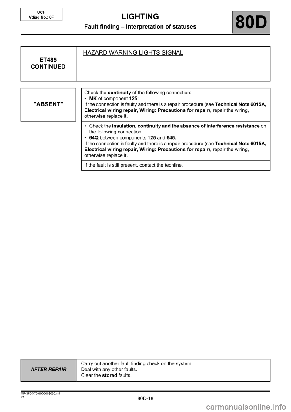
ET485
CONTINUEDHAZARD WARNING LIGHTS SIGNAL
"ABSENT"
Check the continuity of the following connection:
•MK of component 125:
If the connection is faulty and there is a repair procedure (see Technical Note 6015A,
Electrical wiring repair, Wiring: Precautions for repair), repair the wiring,
otherwise replace it.
• Check the insulation, continuity and the absence of interference resistance on
the following connection:
•64Q between components 125 and 645.
If the connection is faulty and there is a repair procedure (see Technical Note 6015A,
Electrical wiring repair, Wiring: Precautions for repair), repair the wiring,
otherwise replace it.
If the fault is still present, contact the techline.
Page 19 of 30
80D-19
AFTER REPAIRCarry out another fault finding check on the system.
Deal with any other faults.
Clear the stored faults.
V1 MR-376-X76-80D000$080.mif
LIGHTING
Fault finding – Interpretation of statuses80D
UCH
Vdiag No.: 0F
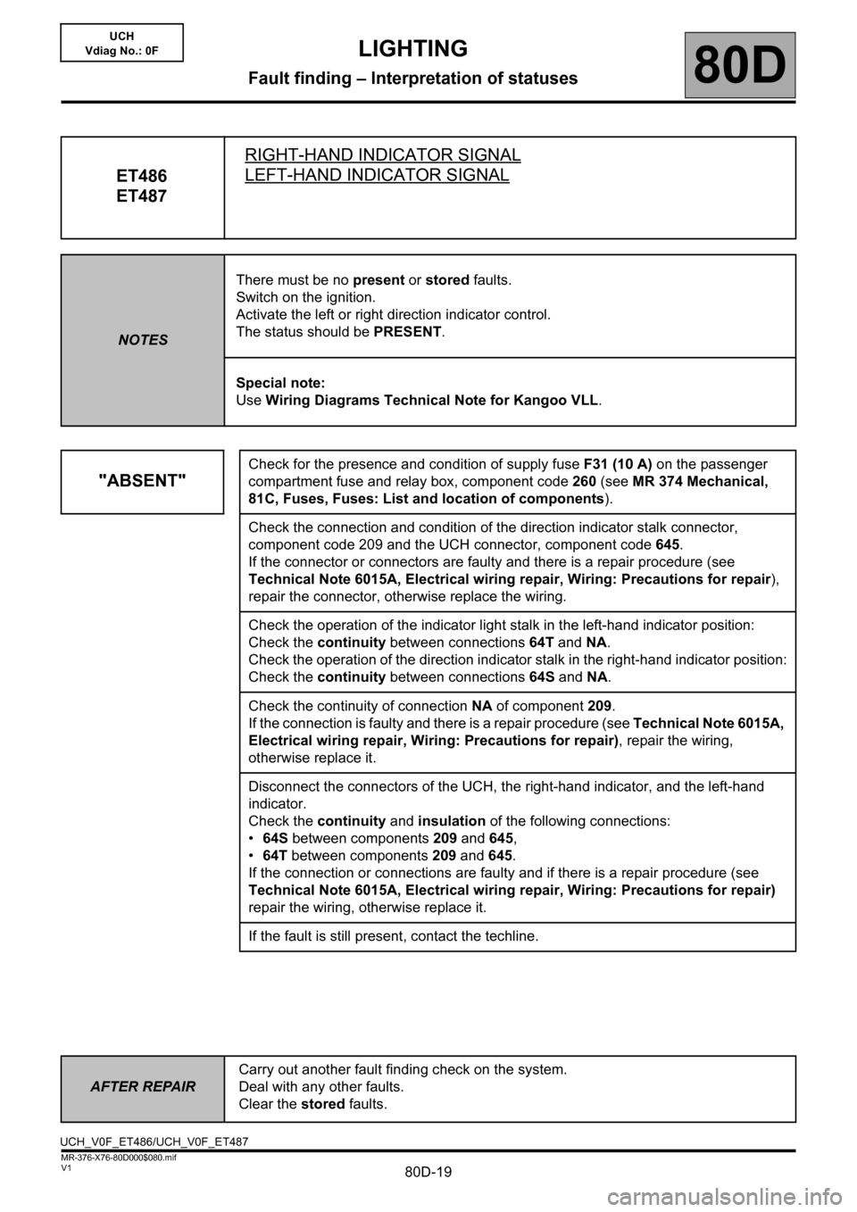
ET486
ET487RIGHT-HAND INDICATOR SIGNALLEFT-HAND INDICATOR SIGNAL
NOTESThere must be no present or stored faults.
Switch on the ignition.
Activate the left or right direction indicator control.
The status should be PRESENT.
Special note:
Use Wiring Diagrams Technical Note for Kangoo VLL.
"ABSENT"
Check for the presence and condition of supply fuse F31 (10 A) on the passenger
compartment fuse and relay box, component code 260 (see MR 374 Mechanical,
81C, Fuses, Fuses: List and location of components).
Check the connection and condition of the direction indicator stalk connector,
component code 209 and the UCH connector, component code 645.
If the connector or connectors are faulty and there is a repair procedure (see
Technical Note 6015A, Electrical wiring repair, Wiring: Precautions for repair),
repair the connector, otherwise replace the wiring.
Check the operation of the indicator light stalk in the left-hand indicator position:
Check the continuity between connections 64T and NA.
Check the operation of the direction indicator stalk in the right-hand indicator position:
Check the continuity between connections 64S and NA.
Check the continuity of connection NA of component 209.
If the connection is faulty and there is a repair procedure (see Technical Note 6015A,
Electrical wiring repair, Wiring: Precautions for repair), repair the wiring,
otherwise replace it.
Disconnect the connectors of the UCH, the right-hand indicator, and the left-hand
indicator.
Check the continuity and insulation of the following connections:
•64S between components 209 and 645,
•64T between components 209 and 645.
If the connection or connections are faulty and if there is a repair procedure (see
Technical Note 6015A, Electrical wiring repair, Wiring: Precautions for repair)
repair the wiring, otherwise replace it.
If the fault is still present, contact the techline.
UCH_V0F_ET486/UCH_V0F_ET487
Page 20 of 30
80D-20V1 MR-376-X76-80D000$090.mif
80D
UCH
Vdiag No.: 0F
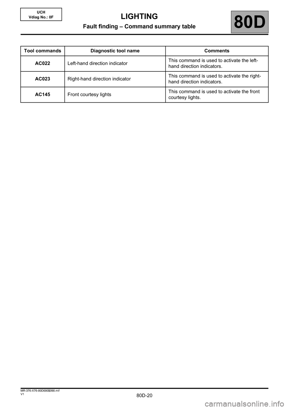
Tool commands Diagnostic tool name Comments
AC022Left-hand direction indicatorThis command is used to activate the left-
hand direction indicators.
AC023Right-hand direction indicatorThis command is used to activate the right-
hand direction indicators.
AC145Front courtesy lightsThis command is used to activate the front
courtesy lights.
LIGHTING
Fault finding – Command summary table