engine RENAULT KANGOO 2013 X61 / 2.G Petrol V42 Injection Workshop Manual
[x] Cancel search | Manufacturer: RENAULT, Model Year: 2013, Model line: KANGOO, Model: RENAULT KANGOO 2013 X61 / 2.GPages: 279, PDF Size: 1.29 MB
Page 171 of 279
17B-171V2 MR-376-X76-17B050$110.mif
PETROL INJECTION
Fault finding – Interpretation of statuses17B
V42 Injection
Program No.: 2A
Vdiag No.: 04, 05, 06,
14, 16, 18
AFTER REPAIRDeal with any faults. Clear the faults from the computer memory.
Switch off the ignition and carry out a road test followed by a test with the diagnostic
tool.
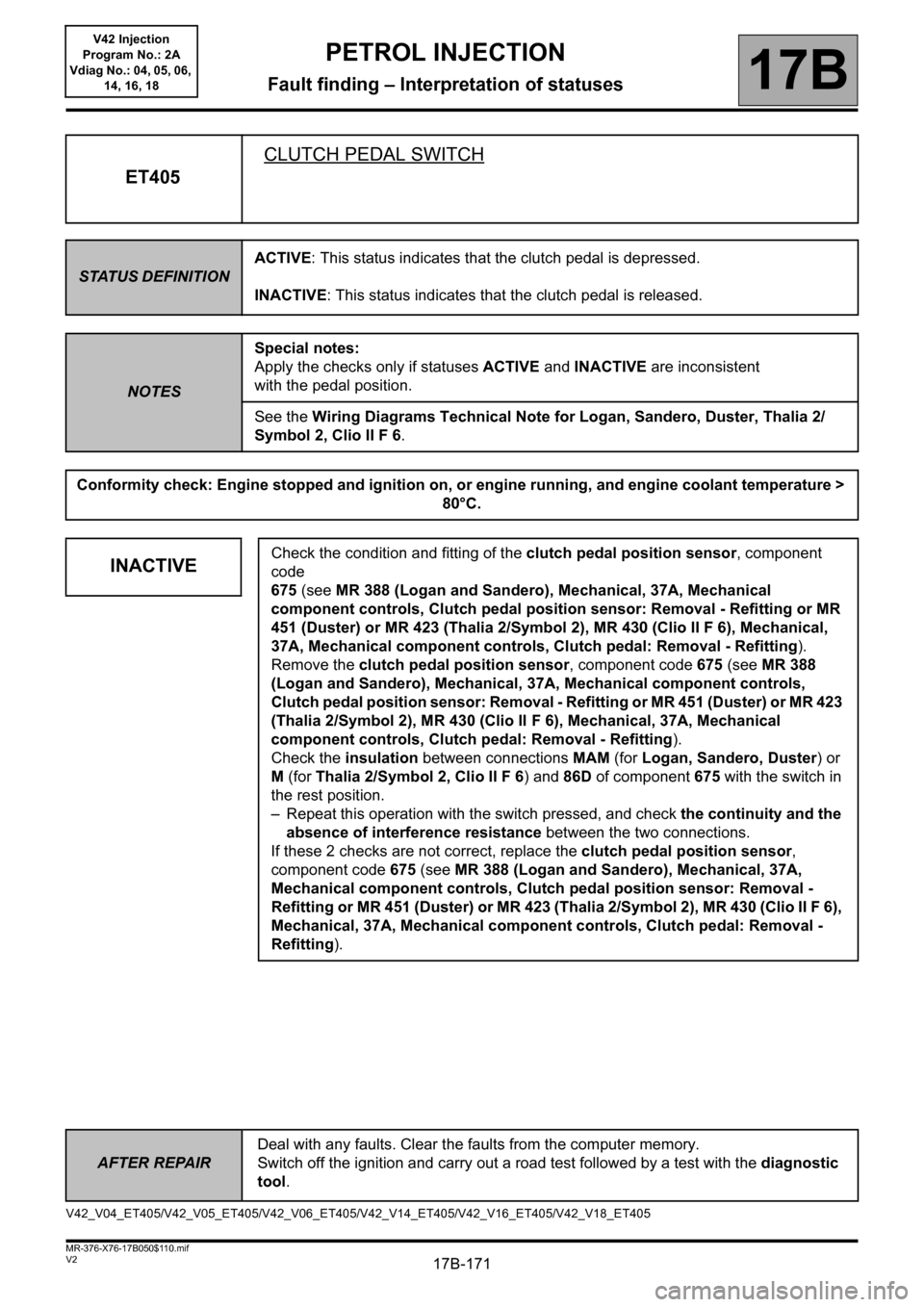
ET405CLUTCH PEDAL SWITCH
STATUS DEFINITIONACTIVE: This status indicates that the clutch pedal is depressed.
INACTIVE: This status indicates that the clutch pedal is released.
NOTESSpecial notes:
Apply the checks only if statuses ACTIVE and INACTIVE are inconsistent
with the pedal position.
See the Wiring Diagrams Technical Note for Logan, Sandero, Duster, Thalia 2/
Symbol 2, Clio II F 6.
Conformity check: Engine stopped and ignition on, or engine running, and engine coolant temperature >
80°C.
INACTIVECheck the condition and fitting of the clutch pedal position sensor, component
code
675 (see MR 388 (Logan and Sandero), Mechanical, 37A, Mechanical
component controls, Clutch pedal position sensor: Removal - Refitting or MR
451 (Duster) or MR 423 (Thalia 2/Symbol 2), MR 430 (Clio II F 6), Mechanical,
37A, Mechanical component controls, Clutch pedal: Removal - Refitting).
Remove the clutch pedal position sensor, component code 675 (see MR 388
(Logan and Sandero), Mechanical, 37A, Mechanical component controls,
Clutch pedal position sensor: Removal - Refitting or MR 451 (Duster) or MR 423
(Thalia 2/Symbol 2), MR 430 (Clio II F 6), Mechanical, 37A, Mechanical
component controls, Clutch pedal: Removal - Refitting).
Check the insulation between connections MAM (for Logan, Sandero, Duster) or
M (for Thalia 2/Symbol 2, Clio II F 6) and 86D of component 675 with the switch in
the rest position.
– Repeat this operation with the switch pressed, and check the continuity and the
absence of interference resistance between the two connections.
If these 2 checks are not correct, replace the clutch pedal position sensor,
component code 675 (see MR 388 (Logan and Sandero), Mechanical, 37A,
Mechanical component controls, Clutch pedal position sensor: Removal -
Refitting or MR 451 (Duster) or MR 423 (Thalia 2/Symbol 2), MR 430 (Clio II F 6),
Mechanical, 37A, Mechanical component controls, Clutch pedal: Removal -
Refitting).
V42_V04_ET405/V42_V05_ET405/V42_V06_ET405/V42_V14_ET405/V42_V16_ET405/V42_V18_ET405
Page 173 of 279
17B-173V2 MR-376-X76-17B050$110.mif
PETROL INJECTION
Fault finding – Interpretation of statuses17B
V42 Injection
Program No.: 2A
Vdiag No.: 04, 05, 06,
14, 16, 18
AFTER REPAIRDeal with any faults. Clear the faults from the computer memory.
Switch off the ignition and carry out a road test followed by a test with the diagnostic
tool.
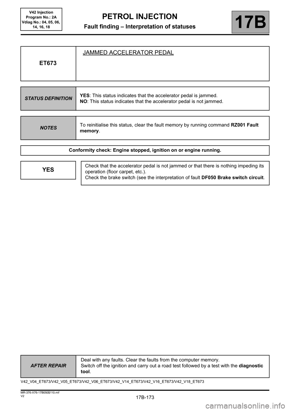
ET673JAMMED ACCELERATOR PEDAL
STATUS DEFINITIONYES: This status indicates that the accelerator pedal is jammed.
NO: This status indicates that the accelerator pedal is not jammed.
NOTESTo reinitialise this status, clear the fault memory by running command RZ001 Fault
memory.
Conformity check: Engine stopped, ignition on or engine running.
YESCheck that the accelerator pedal is not jammed or that there is nothing impeding its
operation (floor carpet, etc.).
Check the brake switch (see the interpretation of fault DF050 Brake switch circuit.
V42_V04_ET673/V42_V05_ET673/V42_V06_ET673/V42_V14_ET673/V42_V16_ET673/V42_V18_ET673
Page 175 of 279
17B-175V2 MR-376-X76-17B050$110.mif
PETROL INJECTION
Fault finding – Interpretation of statuses17B
V42 Injection
Program No.: 2A
Vdiag No.: 04, 05, 06,
14, 16, 18
AFTER REPAIRDeal with any faults. Clear the faults from the computer memory.
Switch off the ignition and carry out a road test followed by a test with the diagnostic
tool.
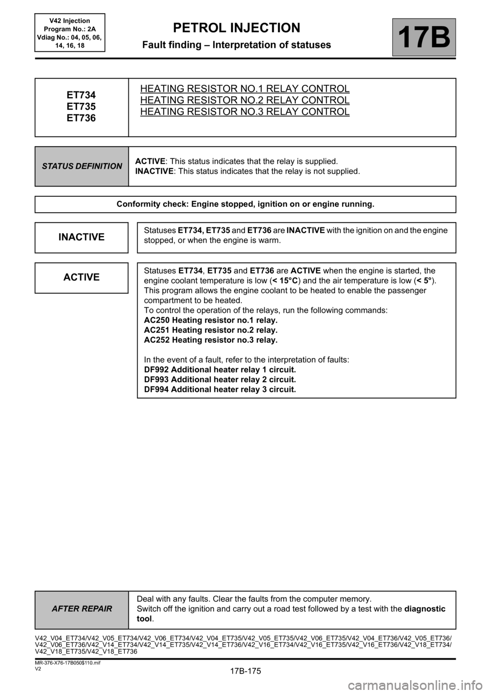
ET734
ET735
ET736HEATING RESISTOR NO.1 RELAY CONTROLHEATING RESISTOR NO.2 RELAY CONTROL
HEATING RESISTOR NO.3 RELAY CONTROL
STATUS DEFINITIONACTIVE: This status indicates that the relay is supplied.
INACTIVE: This status indicates that the relay is not supplied.
Conformity check: Engine stopped, ignition on or engine running.
INACTIVEStatuses ET734, ET735 and ET736 are INACTIVE with the ignition on and the engine
stopped, or when the engine is warm.
ACTIVEStatuses ET734, ET735 and ET736 are ACTIVE when the engine is started, the
engine coolant temperature is low (< 15°C) and the air temperature is low (<5°).
This program allows the engine coolant to be heated to enable the passenger
compartment to be heated.
To control the operation of the relays, run the following commands:
AC250 Heating resistor no.1 relay.
AC251 Heating resistor no.2 relay.
AC252 Heating resistor no.3 relay.
In the event of a fault, refer to the interpretation of faults:
DF992 Additional heater relay 1 circuit.
DF993 Additional heater relay 2 circuit.
DF994 Additional heater relay 3 circuit.
V42_V04_ET734/V42_V05_ET734/V42_V06_ET734/V42_V04_ET735/V42_V05_ET735/V42_V06_ET735/V42_V04_ET736/V42_V05_ET736/
V42_V06_ET736/V42_V14_ET734/V42_V14_ET735/V42_V14_ET736/V42_V16_ET734/V42_V16_ET735/V42_V16_ET736/V42_V18_ET734/
V42_V18_ET735/V42_V18_ET736
Page 176 of 279
17B-176V2 MR-376-X76-17B050$110.mif
PETROL INJECTION
Fault finding – Interpretation of statuses17B
V42 Injection
Program No.: 2A
Vdiag No.: 04, 05, 06,
14, 16, 18
AFTER REPAIRDeal with any faults. Clear the faults from the computer memory.
Switch off the ignition and carry out a road test followed by a test with the diagnostic
tool.
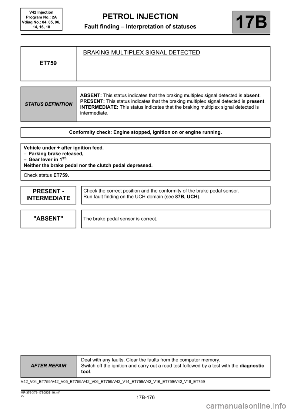
ET759BRAKING MULTIPLEX SIGNAL DETECTED
STATUS DEFINITIONABSENT: This status indicates that the braking multiplex signal detected is absent.
PRESENT: This status indicates that the braking multiplex signal detected is present.
INTERMEDIATE: This status indicates that the braking multiplex signal detected is
intermediate.
Conformity check: Engine stopped, ignition on or engine running.
Vehicle under + after ignition feed.
– Parking brake released,
– Gear lever in 1
st.
Neither the brake pedal nor the clutch pedal depressed.
Check status ET759.
PRESENT -
INTERMEDIATECheck the correct position and the conformity of the brake pedal sensor.
Run fault finding on the UCH domain (see 87B, UCH).
"ABSENT"The brake pedal sensor is correct.
V42_V04_ET759/V42_V05_ET759/V42_V06_ET759/V42_V14_ET759/V42_V16_ET759/V42_V18_ET759
Page 177 of 279
17B-177V2 MR-376-X76-17B050$110.mif
PETROL INJECTION
Fault finding – Interpretation of statuses17B
V42 Injection
Program No.: 2A
Vdiag No.: 04, 05, 06,
14, 16, 18
AFTER REPAIRDeal with any faults. Clear the faults from the computer memory.
Switch off the ignition and carry out a road test followed by a test with the diagnostic
tool.
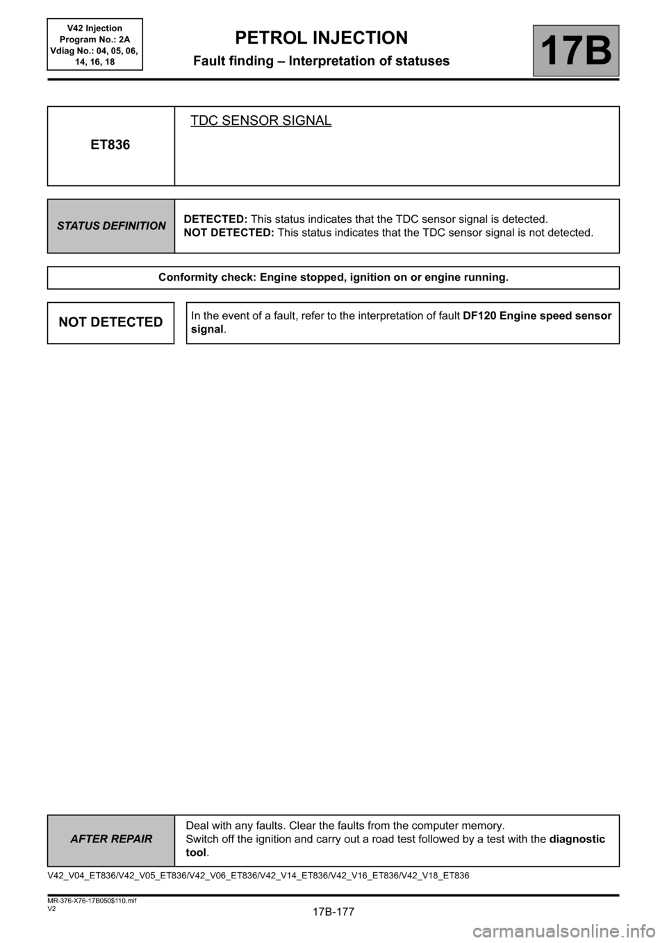
ET836TDC SENSOR SIGNAL
STATUS DEFINITIONDETECTED: This status indicates that the TDC sensor signal is detected.
NOT DETECTED: This status indicates that the TDC sensor signal is not detected.
Conformity check: Engine stopped, ignition on or engine running.
NOT DETECTEDIn the event of a fault, refer to the interpretation of fault DF120 Engine speed sensor
signal.
V42_V04_ET836/V42_V05_ET836/V42_V06_ET836/V42_V14_ET836/V42_V16_ET836/V42_V18_ET836
Page 179 of 279
17B-179V2 MR-376-X76-17B050$110.mif
PETROL INJECTION
Fault finding – Interpretation of statuses17B
V42 Injection
Program No.: 2A
Vdiag No.: 04, 05, 06,
14, 16, 18
AFTER REPAIRDeal with any faults. Clear the faults from the computer memory.
Switch off the ignition and carry out a road test followed by a test with the diagnostic
tool.
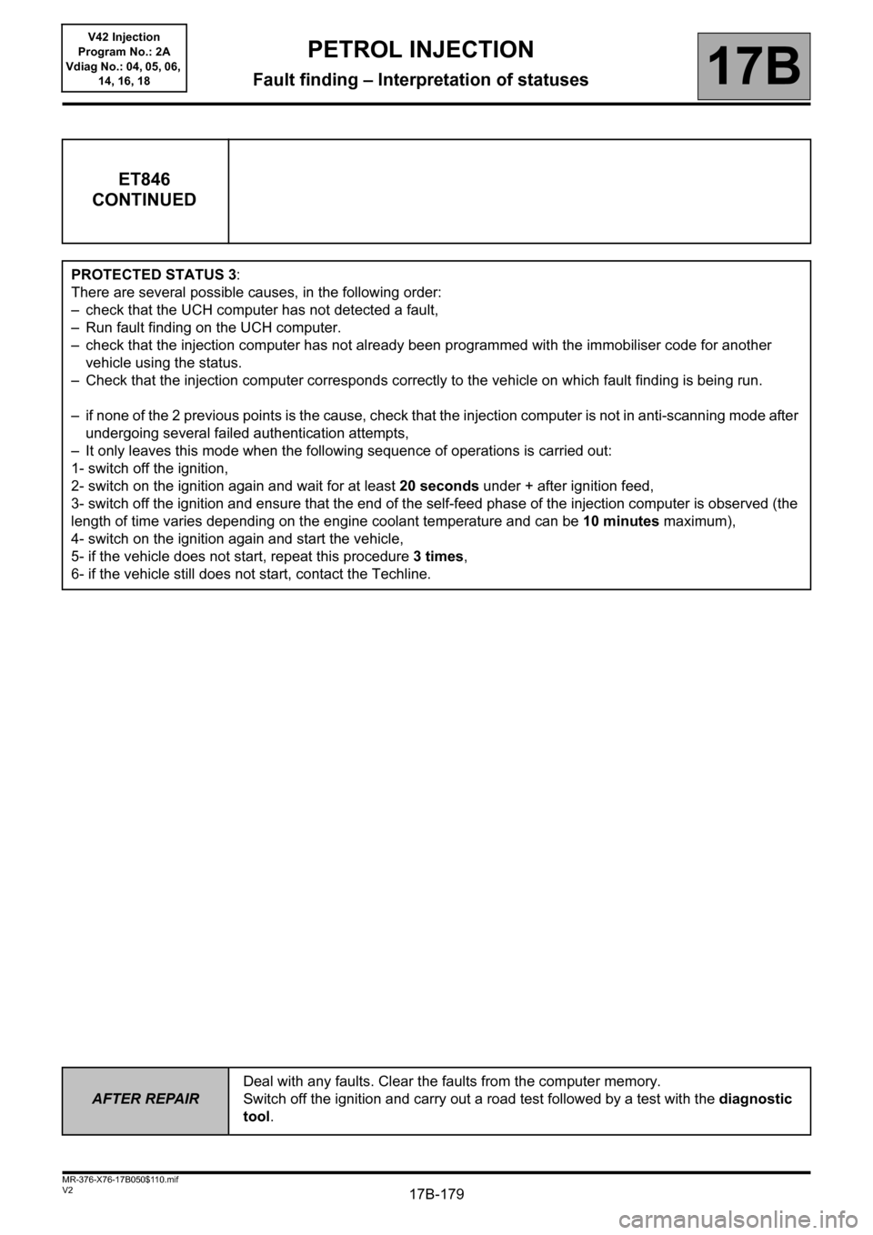
ET846
CONTINUED
PROTECTED STATUS 3:
There are several possible causes, in the following order:
– check that the UCH computer has not detected a fault,
– Run fault finding on the UCH computer.
– check that the injection computer has not already been programmed with the immobiliser code for another
vehicle using the status.
– Check that the injection computer corresponds correctly to the vehicle on which fault finding is being run.
– if none of the 2 previous points is the cause, check that the injection computer is not in anti-scanning mode after
undergoing several failed authentication attempts,
– It only leaves this mode when the following sequence of operations is carried out:
1- switch off the ignition,
2- switch on the ignition again and wait for at least 20 seconds under + after ignition feed,
3- switch off the ignition and ensure that the end of the self-feed phase of the injection computer is observed (the
length of time varies depending on the engine coolant temperature and can be 10 minutes maximum),
4- switch on the ignition again and start the vehicle,
5- if the vehicle does not start, repeat this procedure 3 times,
6- if the vehicle still does not start, contact the Techline.
Page 180 of 279
17B-180V2 MR-376-X76-17B050$120.mif
17B
V42 Injection
Program No.: 2A
Vdiag No.: 04, 05, 06,
14, 16, 18
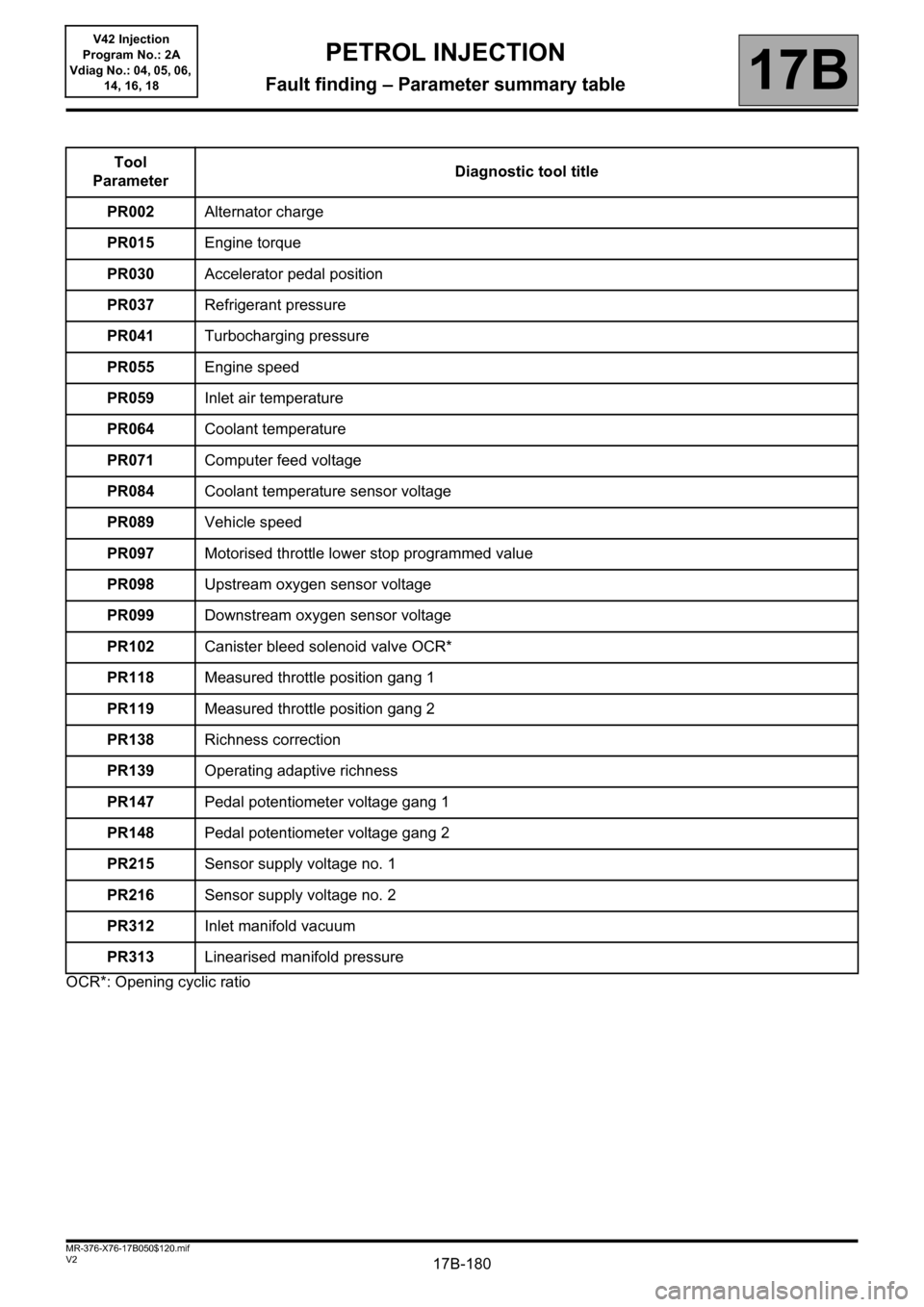
OCR*: Opening cyclic ratioTool
ParameterDiagnostic tool title
PR002 Alternator charge
PR015Engine torque
PR030Accelerator pedal position
PR037Refrigerant pressure
PR041 Turbocharging pressure
PR055Engine speed
PR059 Inlet air temperature
PR064Coolant temperature
PR071 Computer feed voltage
PR084 Coolant temperature sensor voltage
PR089Vehicle speed
PR097Motorised throttle lower stop programmed value
PR098Upstream oxygen sensor voltage
PR099Downstream oxygen sensor voltage
PR102Canister bleed solenoid valve OCR*
PR118Measured throttle position gang 1
PR119Measured throttle position gang 2
PR138Richness correction
PR139 Operating adaptive richness
PR147Pedal potentiometer voltage gang 1
PR148Pedal potentiometer voltage gang 2
PR215 Sensor supply voltage no. 1
PR216 Sensor supply voltage no. 2
PR312Inlet manifold vacuum
PR313 Linearised manifold pressure
PETROL INJECTION
Fault finding – Parameter summary table
Page 182 of 279
17B-182V2 MR-376-X76-17B050$120.mif
PETROL INJECTION
Fault finding – Parameter summary table17B
V42 Injection
Program No.: 2A
Vdiag No.: 04, 05, 06,
14, 16, 18
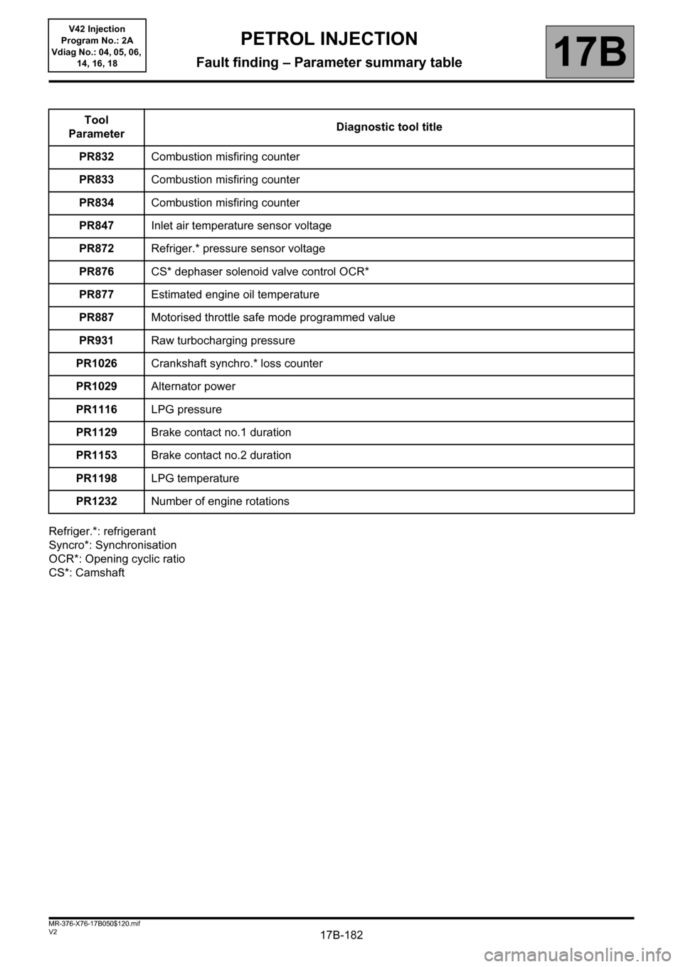
Refriger.*: refrigerant
Syncro*: Synchronisation
OCR*: Opening cyclic ratio
CS*: CamshaftTool
ParameterDiagnostic tool title
PR832Combustion misfiring counter
PR833Combustion misfiring counter
PR834Combustion misfiring counter
PR847Inlet air temperature sensor voltage
PR872Refriger.* pressure sensor voltage
PR876CS* dephaser solenoid valve control OCR*
PR877Estimated engine oil temperature
PR887Motorised throttle safe mode programmed value
PR931Raw turbocharging pressure
PR1026Crankshaft synchro.* loss counter
PR1029 Alternator power
PR1116LPG pressure
PR1129 Brake contact no.1 duration
PR1153 Brake contact no.2 duration
PR1198LPG temperature
PR1232Number of engine rotations
Page 183 of 279
17B-183
AFTER REPAIRDeal with any faults displayed by the diagnostic tool.
Clear the computer memory.
Carry out a road test, then check with the diagnostic tool.
V2 MR-376-X76-17B050$130.mif
17B
V42 Injection
Program No.: 2A
Vdiag No.: 04, 05, 06,
14, 16, 18
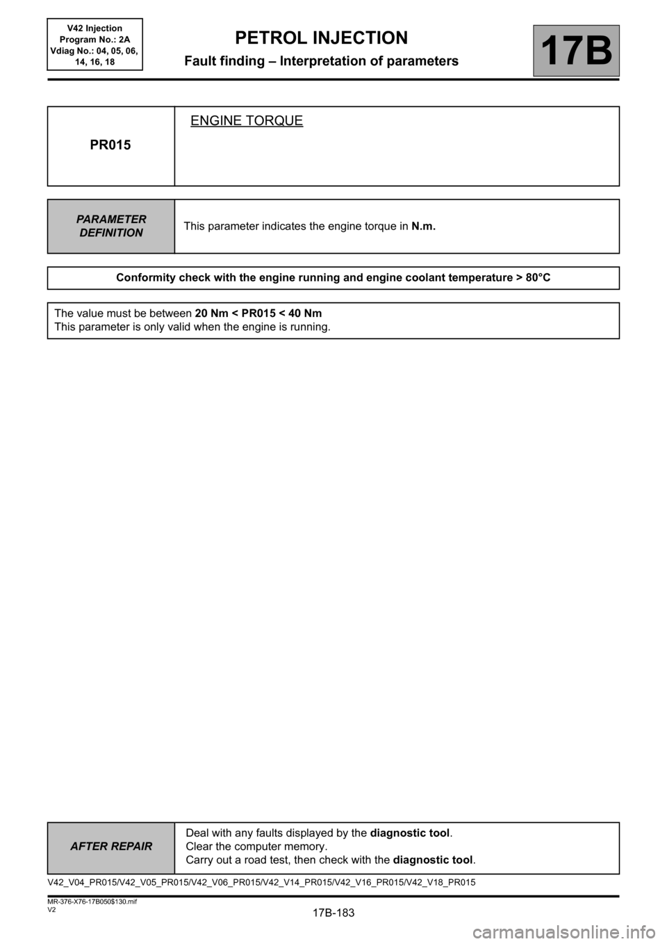
PR015ENGINE TORQUE
PA R A M E T E R
DEFINITIONThis parameter indicates the engine torque in N.m.
Conformity check with the engine running and engine coolant temperature > 80°C
The value must be between 20 Nm < PR015 < 40 Nm
This parameter is only valid when the engine is running.
V42_V04_PR015/V42_V05_PR015/V42_V06_PR015/V42_V14_PR015/V42_V16_PR015/V42_V18_PR015
PETROL INJECTION
Fault finding – Interpretation of parameters
Page 184 of 279
17B-184
AFTER REPAIRCarry out a road test, then check with the diagnostic tool.
V2 MR-376-X76-17B050$130.mif
PETROL INJECTION
Fault finding – Interpretation of parameters17B
V42 Injection
Program No.: 2A
Vdiag No.: 04, 05, 06,
14, 16, 18
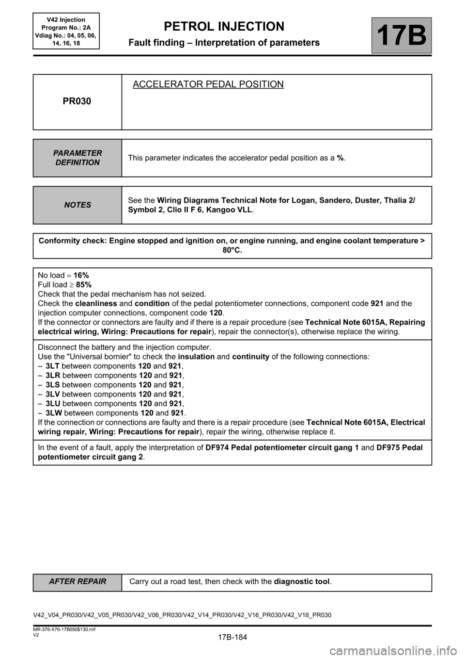
PR030ACCELERATOR PEDAL POSITION
PA R A M E T E R
DEFINITIONThis parameter indicates the accelerator pedal position as a %.
NOTESSee the Wiring Diagrams Technical Note for Logan, Sandero, Duster, Thalia 2/
Symbol 2, Clio II F 6, Kangoo VLL.
Conformity check: Engine stopped and ignition on, or engine running, and engine coolant temperature >
80°C.
No load 16%
Full load 85%
Check that the pedal mechanism has not seized.
Check the cleanliness and condition of the pedal potentiometer connections, component code 921 and the
injection computer connections, component code 120.
If the connector or connectors are faulty and if there is a repair procedure (see Technical Note 6015A, Repairing
electrical wiring, Wiring: Precautions for repair), repair the connector(s), otherwise replace the wiring.
Disconnect the battery and the injection computer.
Use the "Universal bornier" to check the insulation and continuity of the following connections:
–3LT between components 120 and 921,
–3LR between components 120 and 921,
–3LS between components 120 and 921,
–3LV between components 120 and 921,
–3LU between components 120 and 921,
–3LW between components 120 and 921.
If the connection or connections are faulty and there is a repair procedure (see Technical Note 6015A, Electrical
wiring repair, Wiring: Precautions for repair), repair the wiring, otherwise replace it.
In the event of a fault, apply the interpretation of DF974 Pedal potentiometer circuit gang 1 and DF975 Pedal
potentiometer circuit gang 2.
V42_V04_PR030/V42_V05_PR030/V42_V06_PR030/V42_V14_PR030/V42_V16_PR030/V42_V18_PR030