RENAULT SCENIC 2007 J84 / 2.G Anti Lock Braking System Bosch 8.0 ABS Service Manual
Manufacturer: RENAULT, Model Year: 2007, Model line: SCENIC, Model: RENAULT SCENIC 2007 J84 / 2.GPages: 64, PDF Size: 0.2 MB
Page 41 of 64
ANTI-LOCK BRAKING SYSTEM
Fault finding - Interpretation of faults
38C
38C - 41V2 MR-372-J84-38C000$396_eng.mif
BOSCH ABS 8.0
Vdiag No.: 0C, 0D, 0E, 0F
DF188
PRESENT
OR
STOREDBRAKE LIGHT SWITCH CIRCUIT
NOTESSpecial notes:
This fault does not cause illumination of any warning lights, nor does it generate any
fault message.
Conditions for applying the fault finding procedure to stored faults:
Clear the stored fault, carry out a road test at a speed of > 37 mph (60 km/h) and test
the brakes using ABS.
Check the conformity of the brake light bulbs.
Using the diagnostic tool, check on the statuses screen that ET017 Brake pedal displays the pressed and released
positions of the brake pedal correctly.
If the correct pedal position is not displayed, use the interpretation of ET017.
If the fault is still present, contact the Techline.
AFTER REPAIRClear the computer fault memory.
Carry out a road test followed by another check with the diagnostic tool.
ABS8.0_V0C_DF188 /ABS8.0_V0D_DF188/ABS8.0_V0E_DF188/ABS8.0_V0F_DF188 ABS 8.0X84 4.0
Page 42 of 64
ANTI-LOCK BRAKING SYSTEM
Fault finding - Interpretation of faults
38C
38C - 42V2 MR-372-J84-38C000$462_eng.mif
BOSCH ABS 8.0
Vdiag No.: 0C, 0D, 0E, 0FANTI-LOCK BRAKING SYSTEM
Fault finding - Interpretation of faults
DF193
PRESENT
OR
STOREDINVALID INJECTION MULTIPLEX SIGNALS
NOTESSpecial notes:
Although it is stored in the computer, the ABS system is not faulty. The ABS is
deactivated due to unusable information from the injection system. Perform fault
finding on the injection system using the diagnostic tool.
Note:
The injection computer does not always store these transient faults as quickly
as the ABS computer.
If no fault is stored in the injection computer, start the engine; if there is no fault present,
contact the Techline. After solving the injection system fault, clear the ABS computer
fault memory.
Conditions for applying the fault finding procedure to stored faults:
The fault is declared present after starting the engine.
Carry out a multiplex network test and check the injection system with the diagnostic tool.
If the fault is still present, contact the Techline.
AFTER REPAIRClear the computer fault memory.
Carry out a road test followed by another check with the diagnostic tool.
ABS8.0_V0C_DF193 /ABS8.0_V0D_DF193/ABS8.0_V0E_DF193/ABS8.0_V0F_DF193 ABS 8.0X84 4.0
MR-372-J84-38C000$462_eng.mif
Page 43 of 64
ANTI-LOCK BRAKING SYSTEM
Fault finding - Conformity check
38C
38C - 43V2 MR-372-J84-38C000$528_eng.mif
BOSCH ABS 8.0
Vdiag No.: 0C, 0D, 0E, 0FANTI-LOCK BRAKING SYSTEM
Fault finding - Conformity check
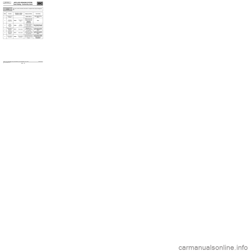
NOTESOnly carry out this conformity check after a complete check using the diagnostic
tool.
Order FunctionParameter or Status
checked or Action Display and Notes Fault finding
1Diagnostic tool
dialogueBOSCH ABS 8.0Apply Fault Finding
Chart 1
2Computer
configurationPR030:Tachometric
indexMake sure the index
entered matches the
vehicle's tyres (see
Replacing
components)None
3Vehicle
parameter
readingPR063:Vehicle
parametersEnsure that the
parameters correspond
to the vehicle
undergoing fault finding.See Configurations and
Programming (VP004)
4Brake pedal not
depressed
detectionET017:Brake pedalReleased status
confirmed, brake pedal
not depressedIn the event of a fault,
apply interpretation of
ET017.
5Depressed
brake pedal
detectionET017:Brake pedal"Depressed" status
confirmed; brake pedal
fully depressedIn the event of a fault,
apply interpretation of
ET017.
6Vehicle speed at
initialisationPR020:Vehicle speed at
initialisationCheck that the value is
correct according to the
information in the Help
sectionIn the event of a fault,
apply parameter VP032
Vehicle speed at
initialisation.
ABS8.0_V0C_CCONF/ABS8.0_V0D_CCONF/ ABS8.0_V0E_CCONF/ABS8.0_V0F_CCONF ABS 8.0X84 4.0
MR-372-J84-38C000$528_eng.mif
Page 44 of 64
ANTI-LOCK BRAKING SYSTEM
38C
38C - 44V2 MR-372-J84-38C000$594_eng.mif
BOSCH ABS 8.0
Vdiag No.: 0C, 0D, 0E, 0FANTI-LOCK BRAKING SYSTEM
Fault finding - List of Statuses and parameters
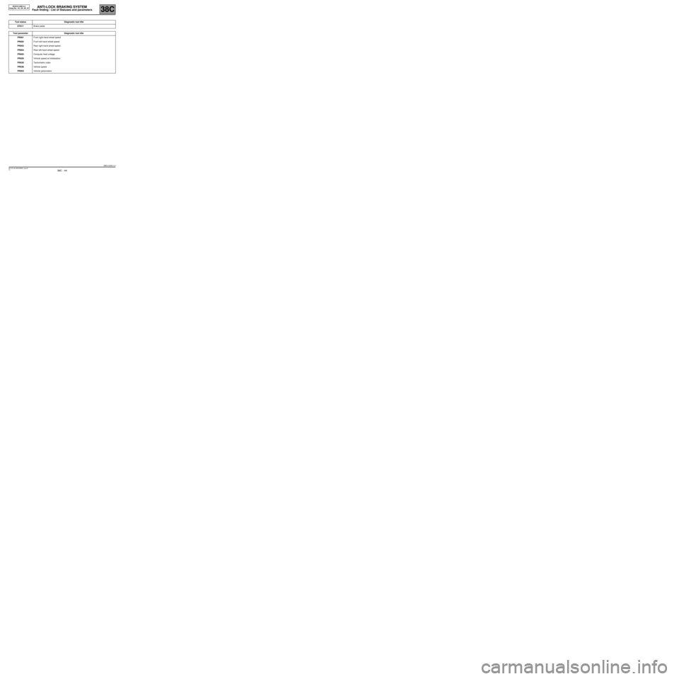
Tool status Diagnostic tool title
ET017Brake pedal
Tool parameter Diagnostic tool title
PR001Front right-hand wheel speed
PR002Front left-hand wheel speed
PR003Rear right-hand wheel speed
PR004Rear left-hand wheel speed
PR005Computer feed voltage
PR020Vehicle speed at initialisation
PR030Tachometric index
PR038Vehicle speed
PR063Vehicle parameters
ABS 8.0X84 4.0
MR-372-J84-38C000$594_eng.mif
Page 45 of 64
ANTI-LOCK BRAKING SYSTEM
Fault finding - Interpretation of statuses
38C
38C - 45V2 MR-372-J84-38C000$660_eng.mif
BOSCH ABS 8.0
Vdiag No.: 0C, 0D, 0E, 0FANTI-LOCK BRAKING SYSTEM
Fault finding - Interpretation of statuses
ET017
BRAKE PEDAL
NOTESSpecial notes:
Carry out the checks only if the "pressed" and "released" statuses are not
consistent with the pedal position.
STATUS IS "RELEASED" WITH BRAKE PEDAL PRESSED.
If brake lights operate:
–Check the continuity of the connection between track 1 of the brake light switch connector and track 20 of the
computer connector.
If the brake lights do not operate:
–Check the condition and fitting of the brake light switch and brake lights fuse.
–Remove the brake light switch and check that it is operating correctly:
Continuity between tracks Insulation between tracks
Switch pressed
(Brake pedal released)3 and 4 1 and 2
Switch released
(Brake pedal depressed)1 and 2 3 and 4
Replace the switch if necessary.
Check for + after ignition feed on tracks 2 and 4 on the brake light switch connector.
AFTER REPAIRClear the computer fault memory.
Carry out a road test followed by another check with the diagnostic tool.
ABS8.0_V0C_ET017/ ABS8.0_V0D_ET017/ABS8.0_V0E_ET017/ABS8.0_V0F_ET017 ABS 8.0X84 4.0
MR-372-J84-38C000$660_eng.mif
Page 46 of 64
ANTI-LOCK BRAKING SYSTEM
Fault finding - Interpretation of statuses
38C
38C - 46V2 MR-372-J84-38C000$660_eng.mif
BOSCH ABS 8.0
Vdiag No.: 0C, 0D, 0E, 0F
ET017
CONTINUED
Status is "pressed" with brake pedal released.
–Check the condition and fitting of the brake light switch, the brake lights fuse and the conformity of the bulbs.
–Remove the brake light switch and check that it is operating correctly:
Continuity between tracks Insulation between tracks
Switch pressed
(Brake pedal released)3 and 4 1 and 2
Switch released
(Brake pedal depressed)1 and 2 3 and 4
–Replace the switch if necessary.
–Check and ensure insulation against 12 V on the connection between track 1 of the brake switch connector and
track 20 of the computer connector.
AFTER REPAIRClear the computer fault memory.
Carry out a road test followed by another check with the diagnostic tool.
ABS 8.0X84 4.0
Page 47 of 64
ANTI-LOCK BRAKING SYSTEM
Fault finding - Parameter procedures
38C
38C - 47V2 MR-372-J84-38C000$726_eng.mif
BOSCH ABS 8.0
Vdiag No.: 0C, 0D, 0E, 0FANTI-LOCK BRAKING SYSTEM
Fault finding - Parameter procedures
PARAMETERS
PR001:Front right-hand wheel speed.
PR002:Front left-hand wheel speed.
PR003:Rear right-hand wheel speed.
PR004:Rear left-hand wheel speed
These parameters show the speed of each wheel of the vehicle in mph.
PR005:Computer supply.
This parameter shows the computer's + after ignition feed voltage in volts.
PR020:Vehicle speed at initialisation
This parameter shows the vehicle speed sent to the multiplex network when the computer is initialised.
(vdiag 0F)
PR030:Tachometric index.
This parameter specifies the tachometric index entered in the computer for the tyres fitted to the vehicle.
PR038:Vehicle speed.
This parameter indicates the vehicle speed in mph (km/h).
PR063:Vehicle parameters
This parameter shows whether the configuration (VP004) correctly matches the vehicle being tested.
(vdiag 0F)
ABS 8.0X84 4.0
MR-372-J84-38C000$726_eng.mif
Page 48 of 64
ANTI-LOCK BRAKING SYSTEM
Fault finding - Dealing with commands
38C
38C - 48V2 MR-372-J84-38C000$792_eng.mif
BOSCH ABS 8.0
Vdiag No.: 0C, 0D, 0E, 0FANTI-LOCK BRAKING SYSTEM
Fault finding - Dealing with commands
CLEARING
RZ001:Fault memory.
This command is used for clearing the computer's stored faults.
ACTIVATION
AC003:
AC004:
AC005:
AC006:Front left-hand wheel solenoid valves.
Front right-hand wheel solenoid valves.
Rear left-hand wheel solenoid valves.
Rear right-hand wheel solenoid valves.
These commands permit a check on the hydraulics of each wheel.
Position the vehicle on a 2-post lift so that the free rotation of the wheels can be checked.
Keep the brake pedal depressed enough to prevent the wheel being tested from being turned by hand (do not brake
so hard that the anti-lock function operates).
Select and confirm the command for the wheel in question (e.g. Left-hand front wheel solenoid valve, etc.).
Turn the wheel concerned by hand: 5 braking/releasing cycles should be detected.
AC013:Wheel speed sensor supply test.
This command is used to check that voltage pulses of approximately 12 V are detected on the faulty
sensor by a multimeter at the terminals of the sensor connector on the computer side.
You must use command AC013 once only.
AC016:Pump motor test.
This command is used to test the pump motor control circuit.
Select command AC016 Pump Motor Test.
The motor must run for 5 seconds.
AC195:Vehicle speed signal.
This command serves to generate a speed other than 0 mph at the computer's vehicle speed wire output
(Track 23) for users of that signal (xenon bulbs, radio, sunroof).
Note:
This command has no visible effect on the dashboard speedometer needle.
–Xenon headlights: Switch on the dipped headlights and run command AC195. Check for slight
variation in the height of the headlight beam while the command is running (the height of the beam is
adjusted to improve visibility according to vehicle speed).
–Radio: Turn on the radio and make sure that the Adjust volume as a function of speed function is
active. Run command AC195. Check that the volume of the sound increases and then decreases
while the command is running.
–Sunroof: This command has no visible effect on the sunroof. This command changes the activation
threshold of the anti-pinch system (the pressure exerted by the sunroof varies with vehicle speed due
to aerodynamic factors).
AC196:Request to switch on hazard warning lights.
This command sends the UCH a request to switch on the hazard warning lights to test their operation
during emergency braking (depending on UCH configuration).
ABS 8.0X84 4.0
MR-372-J84-38C000$792_eng.mif
Page 49 of 64
ANTI-LOCK BRAKING SYSTEM
Fault finding - Dealing with commands
38C
38C - 49V2 MR-372-J84-38C000$792_eng.mif
BOSCH ABS 8.0
Vdiag No.: 0C, 0D, 0E, 0F
SPECIAL COMMANDS
SC001:Check target teeth.
This command tests the condition of the teeth on each wheel.
Select command SC001 Check target teeth. The test result should indicate 48 sprockets.
SC006:Bleed the hydraulic unit and brake circuits.
This command must be used only if abnormally long brake pedal travel is noted during a road test with
ABS control (the system must have been bled beforehand by the usual method).
Select the SC006 "Bleed hydraulic unit and brake circuit" command and follow the instructions given
by the diagnostic tool.
ABS 8.0X84 4.0
Page 50 of 64
ANTI-LOCK BRAKING SYSTEM
Fault finding - Customer complaints
38C
38C - 50V2 MR-372-J84-38C000$858_eng.mif
BOSCH ABS 8.0
Vdiag No.: 0C, 0D, 0E, 0FANTI-LOCK BRAKING SYSTEM
Fault finding - Customer complaints
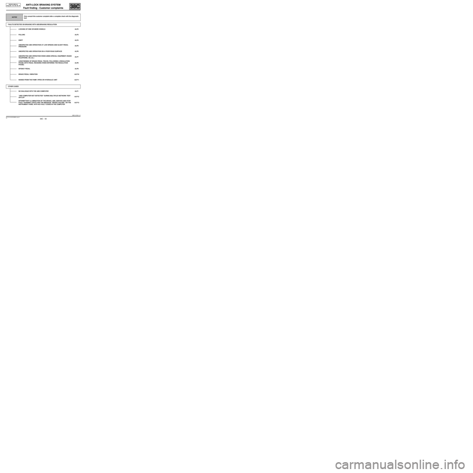
NOTESOnly consult this customer complaint after a complete check with the diagnostic
tool.
FAULTS DETECTED ON BRAKING WITH ABS/BRAKING REGULATION
LOCKING OF ONE OR MORE WHEELS ALP2
PULLINGALP3
DRIFTALP4
UNEXPECTED ABS OPERATION AT LOW SPEEDS AND SLIGHT PEDAL
PRESSUREALP5
UNEXPECTED ABS OPERATION ON A POOR ROAD SURFACE ALP6
UNEXPECTED ABS OPERATION WHEN USING SPECIAL EQUIPMENT (RADIO
TELEPHONE, CB, etc.)ALP7
LENGTHENING OF BRAKE PEDAL TRAVEL FOLLOWING A REGULATION
PHASE (WITH PEDAL RECEDING WHEN ENTERING THE REGULATION
PHASE)ALP8
SPONGY PEDAL ALP9
BRAKE PEDAL VIBRATION ALP10
NOISES FROM THE PUMP, PIPES OR HYDRAULIC UNIT ALP11
OTHER CASES
NO DIALOGUE WITH THE ABS COMPUTER ALP1
"ABS COMPUTER NOT DETECTED" DURING MULTIPLEX NETWORK TEST
ON CLIPALP12
INTERMITTENT ILLUMINATION OF THE BRAKE, ABS, SERVICE AND STOP
FAULT WARNING LIGHTS AND THE MESSAGE “BRAKE FAILURE” ON THE
INSTRUMENT PANEL WITH NO FAULT CODES IN THE COMPUTERALP13
ABS 8.0X84 4.0
MR-372-J84-38C000$858_eng.mif