air condition RENAULT SCENIC 2007 J84 / 2.G Anti Lock Braking System Bosch 8.0 ESP Service Manual
[x] Cancel search | Manufacturer: RENAULT, Model Year: 2007, Model line: SCENIC, Model: RENAULT SCENIC 2007 J84 / 2.GPages: 85, PDF Size: 0.29 MB
Page 58 of 85
ANTI-LOCK BRAKING SYSTEM
BOSCH 8.0 ESP Vdiag No.: 08, 09, 0A, 0B, 11, 1238C
38C - 58V2 MR-372-J84-38C050$496_eng.mif
BOSCH 8.0 ESP
Vdiag No.: 08, 09, 0A,
0B, 11, 12
DF196
PRESENT
OR
STOREDNO ELECTRIC POWER ASSISTED STEERING MULTIPLEX
SIGNAL
NOTESSpecial notes:
Although the fault is stored in the computer, it is not caused by ABS/ESP components,
but it indicates that the ESP is deactivated due to an electric power steering frame
transmission fault. Run fault finding on the electric power steering.
Note:
The electric power steering does not always store these transient faults as quickly as
the ABS/ESP system.
If there is no stored fault in the electric power steering computer memory, start the
engine; if no present fault is displayed, contact the Techline. Once the fault in the
electric power steering system has been repaired, clear the ABS/ESP computer fault
memory.
Priorities when dealing with a number of faults:
Deal with faults DF152 and DF153 first, whether they are present or stored.
Conditions for applying the fault finding procedure to stored faults:
The fault is declared present when the engine is started up.
Check the condition and correct locking of the blue PEH connector on the UPC (Vdiag 44) or the grey CT1
connector on the UPC (Vdiag 48).
Carry out a multiplex network test and check the electric power steering system using the diagnostic tool. If the
fault is still present, contact the Techline.
AFTER REPAIRClear the computer fault memory.
Carry out a road test followed by another check with the diagnostic tool.
ESPBOSCH_V08_DF196 /ESPBOSCH_V09_DF196/ESPBOSCH_V0A_DF196/
ESPBOSCH_V0B_DF196 /ESPBOSCH_V11_DF196/ESPBOSCH_V12_DF196
Page 64 of 85
ANTI-LOCK BRAKING SYSTEM
BOSCH 8.0 ESP Vdiag No.: 08, 09, 0A, 0B, 11, 1238C
38C - 64V2 MR-372-J84-38C050$806_eng.mif
BOSCH 8.0 ESP
Vdiag No.: 08, 09, 0A,
0B, 11, 12ANTI-LOCK BRAKING SYSTEM
ET017
BRAKE PEDAL
NOTESSpecial notes:
Carry out the checks only if the pressed and released statuses are not consistent with
the pedal position.
STATUS Released Brake pedal depressed.
If the brake lights are working:
–Check the continuity of the connection between track 1 of the brake light switch connector and track 30 of the
computer connector.
If the brake lights are not working:
–Check the brake light lighting relay,
–Check the condition and fitting of the brake light switch and brake lights fuse.
–Remove the brake light switch and check that it is operating correctly:
Continuity between tracks Insulation between tracks
Switch pressed
(Brake pedal released)3 and 4 1 and 2
Switch released
(Brake pedal depressed)1 and 2 3 and 4
–Replace the switch if necessary.
–Check for + after ignition feed on tracks 2 and 4 on the brake light switch connector.
If the brake lights still fail, check/ensure the continuity between track 1 of the switch connector and track 4 of the
relay mounting.
AFTER REPAIRClear the computer fault memory.
Carry out a road test followed by another check with the diagnostic tool.
ESPBOSCH_V08_ET017/ESPBOSCH_V09_ET017 /ESPBOSCH_V0A_ET017/
ESPBOSCH_V0B_ET017/ESPBOSCH_V11_ET017/ESPBOSCH_V12_ET017
MR-372-J84-38C050$806_eng.mif
Page 65 of 85
ANTI-LOCK BRAKING SYSTEM
BOSCH 8.0 ESP Vdiag No.: 08, 09, 0A, 0B, 11, 1238C
38C - 65V2 MR-372-J84-38C050$806_eng.mif
BOSCH 8.0 ESP
Vdiag No.: 08, 09, 0A,
0B, 11, 12
ET017
CONTINUED
Pressed STATUS, Brake pedal released.
Check the condition and fitting of the brake light switch, the brake lights fuse and the conformity of the bulbs.
Remove the brake light switch and check that it is operating correctly:
Continuity between tracks Insulation between tracks
Switch pressed
(Brake pedal released)3 and 4 1 and 2
Switch released
(Brake pedal depressed)1 and 2 3 and 4
Replace the switch if necessary.
Check and if necessary repair the insulation from 12 V on the connection between track 1 of the brake light switch
connector and track 30 of the computer connector.
AFTER REPAIRClear the computer fault memory.
Carry out a road test followed by another check with the diagnostic tool.
Page 66 of 85
ANTI-LOCK BRAKING SYSTEM
BOSCH 8.0 ESP Vdiag No.: 08, 09, 0A, 0B, 11, 1238C
38C - 66V2 MR-372-J84-38C050$806_eng.mif
BOSCH 8.0 ESP
Vdiag No.: 08, 09, 0A,
0B, 11, 12
ET023
ESP ON/OFF BUTTON
NOTESSpecial notes:
Carry out the checks only if the "pressed" and "released" statuses are not consistent
with the button position.
STATUS: "Depressed"
Ensure that the ESP start/stop button connector is in good condition and correctly connected. Repair if necessary.
Check there is no continuity between switch tracks A2 and B1 in the released position. If there is continuity,
replace the switch.
Check the continuity and insulation against the earth of the connection between:
Switch connector track B1 Track 31 computer connector
STATUS: "Released"
Ensure that the ESP start/stop button connector is in good condition and correctly connected. Repair if necessary.
Check the continuity between button tracks A2 and B1 in the pressed position. If there is no continuity, replace
the switch.
Check for earth on Track A2 of the button connector.
AFTER REPAIRClear the computer fault memory.
Carry out a road test followed by another check with the diagnostic tool.
ESPBOSCH_V08_ET023/ESPBOSCH_V09_ET023 /ESPBOSCH_V0A_ET023/
ESPBOSCH_V0B_ET023/ESPBOSCH_V11_ET023/ESPBOSCH_V12_ET023
Page 69 of 85
38C-69
MR-372-J84-38C050$930_eng.mif
V2
38C
ANTI-LOCK BRAKING SYSTEM
Diagnostic - Fault finding chart
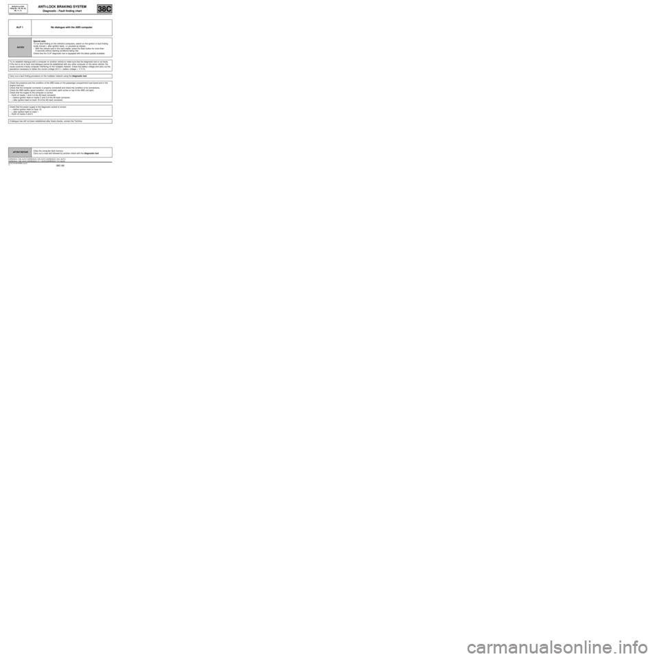
ALP 1 No dialogue with the ABS computer
NOTESSpecial note:
To run fault finding on the vehicle's computers, switch on the ignition in fault finding
mode (forced + after ignition feed), i.e. proceed as follows:
–With the vehicle card in the card reader, press the Start button for more than
5 seconds without starting conditions being met.
Check that the CLIP diagnostic tool is equipped with the latest update available.
Try to establish dialogue with a computer on another vehicle to make sure that the diagnostic tool is not faulty.
If the tool is not at fault, and dialogue cannot be established with any other computer on the same vehicle, the
cause could be a faulty computer interfering on the multiplex network. Check the battery voltage and carry out the
operations necessary to obtain the correct voltage (9.5 V < battery voltage < 17.5 V).
Carry out a fault finding procedure on the multiplex network using the diagnostic tool.
Check the presence and the condition of the ABS fuses on the passenger compartment fuse board and in the
engine fuse box.
Check that the computer connector is properly connected and check the condition of its connections.
Check the ABS earths (good condition, not corroded, earth screw on top of the ABS unit tight).
Check that the supply to the computer is correct:
–Earth on tracks 1 and 4 of the 46-track connector.
–+ before ignition feed on tracks 2 and 3 of the 46-track connector.
–+ after ignition feed on track 18 of the 46-track connector.
Check that the power supply to the diagnostic socket is correct:
–+ before ignition feed on track 16.
–+ after ignition feed on track 1.
–Earth on tracks 4 and 5.
If dialogue has still not been established after these checks, contact the Techline.
AFTER REPAIRClear the computer fault memory.
Carry out a road test followed by another check with the diagnostic tool.
ESPBOSCH_V08_ALP01 /ESPBOSCH_V09_ALP01/ESPBOSCH_V0A_ALP01/
ESPBOSCH_V0B_ALP01 /ESPBOSCH_V11_ALP01/ESPBOSCH_V12_ALP01BOSCH 8.0 ESP
Vdiag No.: 08, 09, 0A,
0B, 11, 12
MR-372-J84-38C050$930_eng.mif
Page 70 of 85
38C-70
MR-372-J84-38C050$930_eng.mif
V2
ANTI-LOCK BRAKING SYSTEM
Diagnostic - Fault finding chart38C
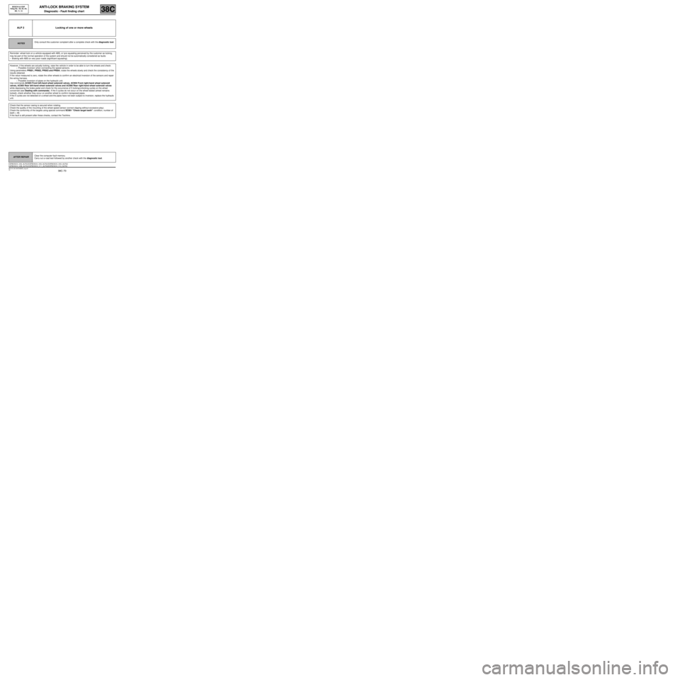
ALP 2 Locking of one or more wheels
NOTESOnly consult this customer complaint after a complete check with the diagnostic tool.
Reminder: wheel lock on a vehicle equipped with ABS, or tyre squealing perceived by the customer as locking,
may be part of the normal operation of the system and should not be automatically considered as faults:
–Braking with ABS on very poor roads (significant squealing).
However, if the wheels are actually locking, raise the vehicle in order to be able to turn the wheels and check:
–Possible inversion when connecting the speed sensors.
Using parameters PR001, PR002, PR003 and PR004, rotate the wheels slowly and check the consistency of the
results obtained.
If the value measured is zero, rotate the other wheels to confirm an electrical inversion of the sensors and repair
the wiring harness.
–Possible inversion of pipes on the hydraulic unit.
Use commands AC003 Front left-hand wheel solenoid valves, AC004 Front right-hand wheel solenoid
valves, AC005 Rear left-hand wheel solenoid valves and AC006 Rear right-hand wheel solenoid valves
while depressing the brake pedal and check for the occurrence of 5 locking/unlocking cycles on the wheel
concerned (see Dealing with commands). If the 5 cycles do not occur on the wheel tested (wheel remains
locked), check whether they occur on another wheel to confirm transposed pipes.
If the 5 cycles are not detected on a wheel and the pipes have not been subject to inversion, replace the hydraulic
unit.
Check that the sensor casing is secured when rotating.
Check the quality of the mounting of the wheel speed sensor (correct clipping without excessive play).
Check the conformity of the targets using special command SC001 "Check target teeth": condition, number of
teeth = 48.
If the fault is still present after these checks, contact the Techline.
AFTER REPAIRClear the computer fault memory.
Carry out a road test followed by another check with the diagnostic tool.
ESPBOSCH_V08_ALP02 /ESPBOSCH_V09_ALP02/ESPBOSCH_V0A_ALP02/
ESPBOSCH_V0B_ALP02 /ESPBOSCH_V11_ALP02/ESPBOSCH_V12_ALP02BOSCH 8.0 ESP
Vdiag No.: 08, 09, 0A,
0B, 11, 12
Page 71 of 85
38C-71
MR-372-J84-38C050$930_eng.mif
V2
ANTI-LOCK BRAKING SYSTEM
Diagnostic - Fault finding chart38C
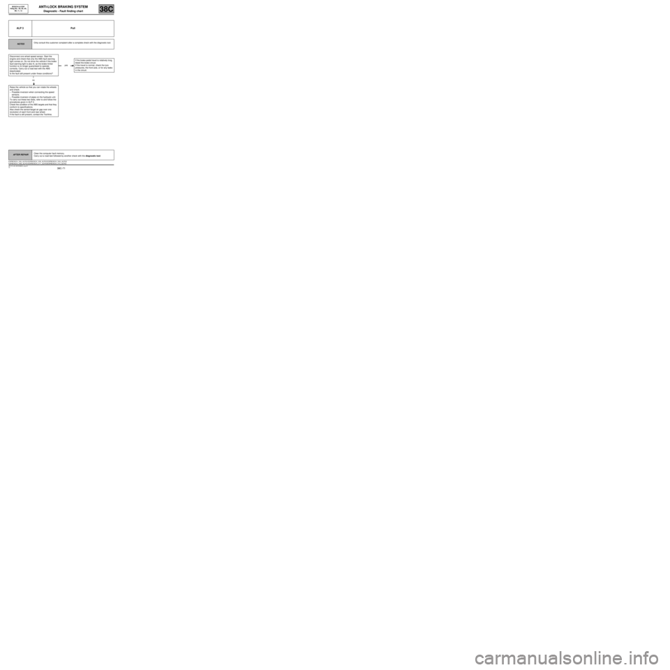
ALP 3 Pull
NOTESOnly consult this customer complaint after a complete check with the diagnostic tool.
Disconnect one wheel speed sensor. Start the
engine and check that only the ABS fault warning
light comes on. Do not drive the vehicle if the brake
fault warning light is also lit, as the brake limiter
function is no longer guaranteed to operate
correctly. Carry out a road test with the ABS
deactivated.
Is the fault still present under these conditions?
no
Raise the vehicle so that you can rotate the wheels
and check:
–Possible inversion when connecting the speed
sensors.
–Possible inversion of pipes on the hydraulic unit.
To carry out these two tests, refer to and follow the
procedures given in ALP 2.
Check the condition of the ABS targets and that they
conform to specifications.
Also check the sensor/target air gap over one
revolution of each front and rear wheel.
If the fault is still present, contact the Techline.
yesIf the brake pedal travel is relatively long,
bleed the brake circuit.
If the travel is normal, check the tyre
pressures, the front axle, or for any leaks
in the circuit.
AFTER REPAIRClear the computer fault memory.
Carry out a road test followed by another check with the diagnostic tool.
ESPBOSCH_V08_ALP03 /ESPBOSCH_V09_ALP03/ESPBOSCH_V0A_ALP03/
ESPBOSCH_V0B_ALP03 /ESPBOSCH_V11_ALP03/ESPBOSCH_V12_ALP03BOSCH 8.0 ESP
Vdiag No.: 08, 09, 0A,
0B, 11, 12
Page 72 of 85
38C-72
MR-372-J84-38C050$930_eng.mif
V2
ANTI-LOCK BRAKING SYSTEM
Diagnostic - Fault finding chart38C
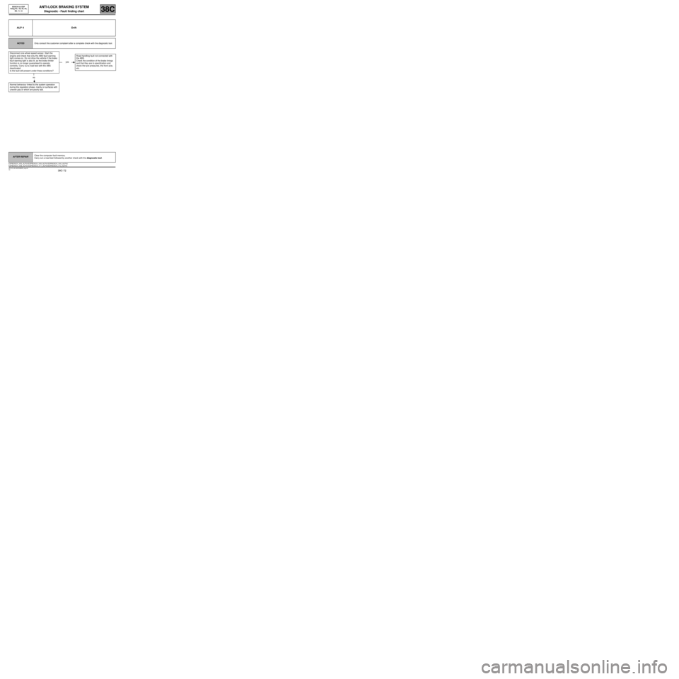
ALP 4 Drift
NOTESOnly consult this customer complaint after a complete check with the diagnostic tool.
Disconnect one wheel speed sensor. Start the
engine and check that only the ABS fault warning
light comes on. Do not drive the vehicle if the brake
fault warning light is also lit, as the brake limiter
function is no longer guaranteed to operate
correctly. Carry out a road test with the ABS
deactivated.
Is the fault still present under these conditions?
no
Normal behaviour linked to the system operation
during the regulation phase, mainly on surfaces with
uneven grip or which are poorly laid.
yesRoad handling fault not connected with
the ABS.
Check the condition of the brake linings
and that they are to specification and
check the tyre pressures, the front axle,
etc.
AFTER REPAIRClear the computer fault memory.
Carry out a road test followed by another check with the diagnostic tool.
ESPBOSCH_V08_ALP04 /ESPBOSCH_V09_ALP04/ESPBOSCH_V0A_ALP04/
ESPBOSCH_V0B_ALP04 /ESPBOSCH_V11_ALP04/ESPBOSCH_V12_ALP04
BOSCH 8.0 ESP
Vdiag No.: 08, 09, 0A,
0B, 11, 12
Page 79 of 85
38C-79
MR-372-J84-38C050$930_eng.mif
V2
ANTI-LOCK BRAKING SYSTEM
Diagnostic - Fault finding chart38C
ALP 11 Noise from the pump, pipes or hydraulic unit
NOTESOnly consult this customer complaint after a complete check with the diagnostic tool.
–Vibration of the unit: check the presence and the condition of the unit bracket insulating rubber mounting
bushes.
–Vibration of pipes: check that all the pipes are securely clipped in their retaining clips and that there is no
contact between pipes or between pipes and bodywork.
To determine where the noise is coming from, use the front left-hand wheel solenoid valves, front right-hand wheel
solenoid valves, rear left-hand wheel solenoid valves and rear right-hand wheel solenoid valves control
commands while depressing the brake pedal.
AFTER REPAIRClear the computer fault memory.
Carry out a road test followed by another check with the diagnostic tool.
ESPBOSCH_V08_ALP11/ESPBOSCH_V09_ALP11/ESPBOSCH_V0A_ALP11/
ESPBOSCH_V0B_ALP11/ESPBOSCH_V11_ALP11/ESPBOSCH_V12_ALP11BOSCH 8.0 ESP
Vdiag No.: 08, 09, 0A,
0B, 11, 12
Page 82 of 85
38C-82
MR-372-J84-38C050$930_eng.mif
V2
ANTI-LOCK BRAKING SYSTEM
Diagnostic - Fault finding chart38C
ALP14 Erratic ESP regulation
NOTESOnly consult this customer complaint after a complete check with the diagnostic
tool.
Check that the four tyres on the vehicle are identical.
Using the diagnostic tool, you must ensure that the value of configuration PR063 "Vehicle parameters"
matches the definition of the vehicle undergoing diagnostics.
If necessary, run command VP004 Vehicle parameters using the diagnostic tool to define the appropriate
parameters for the vehicle type.
Check the connection and condition of the combined sensor connector.
Check that the orientation of the combined sensor on the body is correct and that it is correctly mounted.
Calibrate the steering wheel angle in the Electric power-assisted steering domain using the diagnostic tool.
Clear the computer's fault memory and clear the ESP sensor programming (Vdiag 09, 0A, 0B, 12 and 11) with
command RZ003 "ESP sensor programming".
Carry out a road test followed by another check with the diagnostic tool.
If the fault is still present, adjust the axle assembly geometries. Adjust if necessary and calibrate the steering
wheel angle again in the Electric power assisted steering domain using the diagnostic tool.
Clear the computer's fault memory and clear the ESP sensor programming (Vdiag 09, 0A, 0B, 12 and 11) with
command RZ003 "ESP sensor programming".
If the fault is still present, contact the Techline.
AFTER REPAIRClear the computer fault memory.
Carry out a road test followed by another check with the diagnostic tool.
ESPBOSCH_V08_ALP14 /ESPBOSCH_V09_ALP14/ESPBOSCH_V0A_ALP14/
ESPBOSCH_V0B_ALP14 /ESPBOSCH_V11_ALP14/ESPBOSCH_V12_ALP14BOSCH 8.0 ESP
Vdiag No.: 08, 09, 0A,
0B, 11, 12