display RENAULT SCENIC 2007 J84 / 2.G Automatic Transmission Siemens TA2005 Owner's Manual
[x] Cancel search | Manufacturer: RENAULT, Model Year: 2007, Model line: SCENIC, Model: RENAULT SCENIC 2007 J84 / 2.GPages: 139, PDF Size: 0.43 MB
Page 86 of 139
AUTOMATIC TRANSMISSION
Fault finding - Conformity check
23A
23A - 86V5 MR-372-J84-23A100$464.mif
SIEMENS TA2005
Vdiag No.: 14-18
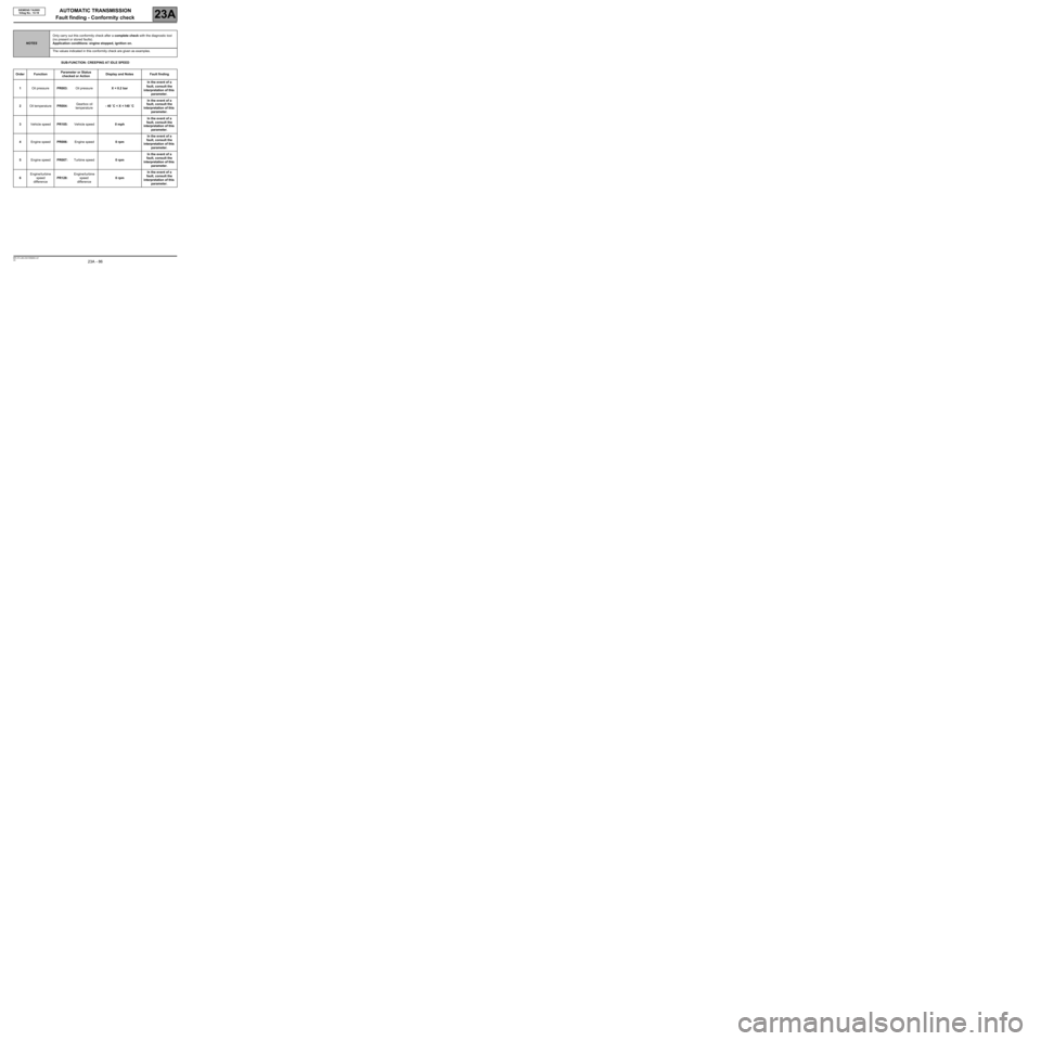
SUB-FUNCTION: CREEPING AT IDLE SPEED
NOTESOnly carry out this conformity check after a complete check with the diagnostic tool
(no present or stored faults).
Application conditions: engine stopped, ignition on.
The values indicated in this conformity check are given as examples.
Order FunctionParameter or Status
checked or ActionDisplay and Notes Fault finding
1Oil pressurePR003:Oil pressureX < 0.2 barIn the event of a
fault, consult the
interpretation of this
parameter.
2Oil temperature PR004:Gearbox oil
temperature- 40 ˚C < X < 140 ˚CIn the event of a
fault, consult the
interpretation of this
parameter.
3Vehicle speedPR105:Vehicle speed0 mphIn the event of a
fault, consult the
interpretation of this
parameter.
4Engine speedPR006:Engine speed0 rpmIn the event of a
fault, consult the
interpretation of this
parameter.
5Engine speedPR007:Turbine speed0 rpmIn the event of a
fault, consult the
interpretation of this
parameter.
6Engine/turbine
speed
differencePR128:Engine/turbine
speed
difference0 rpmIn the event of a
fault, consult the
interpretation of this
parameter.
Page 87 of 139
AUTOMATIC TRANSMISSION
Fault finding - Conformity check
23A
23A - 87V5 MR-372-J84-23A100$464.mif
SIEMENS TA2005
Vdiag No.: 14-18
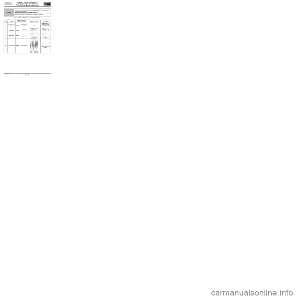
SUB-FUNCTION: CREEPING AT IDLE SPEED (CONTINUED)
NOTESOnly carry out this conformity check after a complete check with the diagnostic tool
(no present or stored faults).
Application conditions: engine stopped, ignition on.
The values indicated in this conformity check are given as examples.
Order FunctionParameter or Status
checked or ActionDisplay and Notes Fault finding
7Standard pedal
positionPR135:Standard pedal
position%In the event of a
fault, consult the
interpretation of this
parameter.
8Brake pedalET003:Brake light
switch (opening)OPEN, brake pedal
released.
CLOSED, brake pedal
depressed.In the event of a
fault, refer to the
interpretation of this
status.
9Brake pedalET004:Brake light
switch (closure)CLOSED, brake pedal
released.
OPEN, brake pedal
depressed.In the event of a
fault, refer to the
interpretation of this
status.
10Gear engagedET013:Gear engagedR for reverse.
1P for 1
st locked.
2P for 2nd locked.
3P for 3rd locked.
4P for 4th locked.
1G for 1st slipping.
2G for 2nd slipping.
3G for 3rd slipping.
4G for 4th slipping.
1 for 1st unlocked.
2 for 2nd unlocked.
3 for 3rd unlocked.
4 for 4th unlocked.In the event of a
fault, refer to the
interpretation of this
status.
Page 90 of 139
AUTOMATIC TRANSMISSION
Fault finding - Interpretation of statuses
23A
23A-90V5 MR-372-J84-23A100$580.mif
SIEMENS TA2005
Vdiag No.: 14-18
ET003
BRAKE LIGHT SWITCH (OPENING)
NOTESThere must be no present or stored faults.
The status displays "OPEN" with the pedal released and changes to "CLOSED" with the brake pedal depressed.
Check the cleanliness and the condition of the brake light switch connections.
Check the position, setting and correct operation of the brake light switch. (Watch out for the floor carpet which can
jam the switch.)
Disconnect the battery.
Disconnect the computer. Check the cleanliness and condition of the connections.
Use the Universal bornier Elé. 1681 to check the insulation, continuity and the absence of interference resistance
on the following connection:
●connection code 5A, between components 119 and 160.
If the connection is faulty and there is a repair procedure (see Technical Note 6015A, Electrical wiring repair,
Wiring: Precautions for repair), repair the wiring, otherwise replace it.
If the correct status is not displayed, replace the switch.
AFTER REPAIRRepeat the conformity check from the start.
DP0TA2005_V14_ET003/DP0TA2005_V18_ET003
Page 91 of 139
AUTOMATIC TRANSMISSION
Fault finding - Interpretation of statuses
23A
23A-91V5 MR-372-J84-23A100$580.mif
SIEMENS TA2005
Vdiag No.: 14-18
ET004
STOP LIGHT SWITCH (CLOSURE)
NOTESThere must be no present or stored faults.
The status displays "CLOSED" with the pedal released and changes to "OPEN" with the brake pedal depressed.
Check the cleanliness and the condition of the brake light switch connections.
Check the position, setting and correct operation of the brake light switch. (Watch out for the floor carpet which
can jam the switch.)
Disconnect the battery.
Disconnect the computer. Check the cleanliness and condition of the connections.
Use the Universal bornier Elé. 1681 to check the insulation, continuity and the absence of interference
resistance on the following connection:
●connection code 5A, between components 119 and 160.
If the connection is faulty and there is a repair procedure (see Technical Note 6015A, Electrical wiring repair,
Wiring: Precautions for repair), repair the wiring, otherwise replace it.
If the correct status is not displayed, replace the switch.
AFTER REPAIRRepeat the conformity check from the start.
DP0TA2005_V14_ET004/DP0TA2005_V18_ET004
Page 92 of 139
AUTOMATIC TRANSMISSION
Fault finding - Interpretation of statuses
23A
23A-92V5 MR-372-J84-23A100$580.mif
SIEMENS TA2005
Vdiag No.: 14-18
ET010
OIL TOO HOT SIGNAL
NOTESThere must be no present or stored faults.
This status means the oil temperature is above the normal operation temperature.
The status displays "NO" if the gearbox oil temperature is below 140 ˚C.
The status displays "YES" when the gearbox oil temperature rises above 140 ˚C.
If the correct status is not displayed, use the interpretation of fault DF177 "Automatic transmission
overheating".
AFTER REPAIRRepeat the conformity check from the start.
DP0TA2005_V14_ET010/DP0TA2005_V18_ET010
Page 96 of 139
AUTOMATIC TRANSMISSION
Fault finding - Interpretation of statuses
23A
23A-96V5 MR-372-J84-23A100$580.mif
SIEMENS TA2005
Vdiag No.: 14-18
* EV: Solenoid valve.ET020
EXCHANGER FLOW CONTROL SOLENOID VALVE*
NOTESThere must be no present or stored faults.
The exchanger flow control solenoid valve command status displays "ACTIVE" in the following conditions:
–gearbox oil temperature is above 100˚C,
–engine speed is greater than 2000 rpm.
With other conditions, the solenoid valve status displays "INACTIVE".
Disconnect the computer. Check the cleanliness and condition of the connectors.
Check the continuity of the following connections:
●connection code 5DD, between components 119 and 1019,
●connection code 5DN, between components 119 and 1019.
If the connection or connections are faulty and there is a repair procedure (see Technical Note 6015A, Electrical
wiring repair, Wiring: Precautions for repair), repair the wiring, otherwise replace it.
Measure the resistance of component 1019 between the following connections:
●connection code 5DD,
●connection code 5DN.
The value should be 40 Ω ± 2 at approximately 23 ˚C.
If the connection or connections are faulty and there is a repair procedure (see Technical Note 6015A, Electrical
wiring repair, Wiring: Precautions for repair), repair the wiring, otherwise replace it.
If the resistance is greater than 50 Ω, check the wiring harness, computer connector and modular connector.
If the status of the command fails to change, use the interpretation of fault DF017 "Exchanger flow solenoid valve
circuit".
AFTER REPAIRRepeat the conformity check from the start.
DP0TA2005_V14_ET020/DP0TA2005_V18_ET020
Page 97 of 139
AUTOMATIC TRANSMISSION
Fault finding - Interpretation of statuses
23A
23A-97V5 MR-372-J84-23A100$580.mif
SIEMENS TA2005
Vdiag No.: 14-18
ET021
SEQUENCE SOLENOID VALVE 1 CONTROL
NOTESThere must be no present or stored faults.
This status displays "ACTIVE" when the gear engaged is "3" or "4" and "INACTIVE" when other gears are
engaged.
Disconnect the computer. Check the cleanliness and condition of the connectors.
Check the continuity between track 10 of the computer connector and track B8 of the modular connector.
Check the continuity of the following connections:
●connection code 5AV, between components 119 and 754.
If the connection is faulty and there is a repair procedure (see Technical Note 6015A, Electrical wiring repair,
Wiring: Precautions for repair), repair the wiring, otherwise replace it.
Measure the resistance of component 754 between the following connections:
●connection code 5AV,
●connection code 5AU.
The value should be 40 Ω ± 2 at approximately 23 ˚C.
If the connection or connections are faulty and there is a repair procedure (see Technical Note 6015A, Electrical
wiring repair, Wiring: Precautions for repair), repair the wiring, otherwise replace it.
If the resistance is greater than 50 Ω, check the wiring harness, computer connector and modular connector.
If the status does not function as specified, use the interpretation of fault DF085 "EVS1 Sequence solenoid valve
circuit".
AFTER REPAIRRepeat the conformity check from the start.
DP0TA2005_V14_ET021/DP0TA2005_V18_ET021
Page 98 of 139
AUTOMATIC TRANSMISSION
Fault finding - Interpretation of statuses
23A
23A-98V5 MR-372-J84-23A100$580.mif
SIEMENS TA2005
Vdiag No.: 14-18
ET022
SEQUENCE SOLENOID VALVE 2 CONTROL
NOTESThere must be no present or stored faults.
This status displays "ACTIVE" when the gear engaged is "N" or "2" or "3" or "4" and "INACTIVE" when other
gears are engaged.
Disconnect the computer. Check the cleanliness and condition of the connectors.
Check the continuity of the following connections:
●connection code 5AW, between components 119 and 754.
If the connection is faulty and there is a repair procedure (see Technical Note 6015A, Electrical wiring repair,
Wiring: Precautions for repair), repair the wiring, otherwise replace it.
Measure the resistance of component 754 between the following connections:
●connection code 5AW,
●connection code 5AU.
The value should be 40 Ω ± 2 at approximately 23 ˚C.
If any of the connections are faulty and there is a repair procedure (see Technical Note 6015A, Electrical wiring
repair, Wiring: Precautions for repair), repair the wiring, otherwise replace it.
If the resistance is greater than 50 Ω, check the wiring harness, computer connector and modular connector.
If the status does not function as specified, use the interpretation of fault DF086 "EVS2 Sequence solenoid valve
circuit".
AFTER REPAIRRepeat the conformity check from the start.
DP0TA2005_V14_ET022/DP0TA2005_V18_ET022
Page 99 of 139
AUTOMATIC TRANSMISSION
Fault finding - Interpretation of statuses
23A
23A-99V5 MR-372-J84-23A100$580.mif
SIEMENS TA2005
Vdiag No.: 14-18
ET023
SEQUENCE SOLENOID VALVE 3 CONTROL
NOTESThere must be no present or stored faults.
This status displays "ACTIVE" when the gear engaged is "P" or "N" or "1" and "INACTIVE" when other gears
are engaged.
Disconnect the computer. Check the cleanliness and condition of the connectors.
Check the continuity of the following connections:
●connection code 5AX, between components 119 and 754.
If the connection is faulty and there is a repair procedure (see Technical Note 6015A, Electrical wiring repair,
Wiring: Precautions for repair), repair the wiring, otherwise replace it.
Measure the resistance of component 754 between the following connections:
●connection code 5AX,
●connection code 5AU.
The value should be 40 Ω ± 2 at approximately 23 ˚C.
If the connection or connections are faulty and there is a repair procedure (see Technical Note 6015A, Electrical
wiring repair, Wiring: Precautions for repair), repair the wiring, otherwise replace it.
If the resistance is greater than 50 Ω, check the wiring harness, the computer connector and the modular
connector.
If the status does not function as specified, use the interpretation of fault DF087 "EVS3 Sequence solenoid valve
circuit".
AFTER REPAIRRepeat the conformity check from the start.
Make sure that shifting up and down through each gear works properly.
DP0TA2005_V14_ET023/DP0TA2005_V18_ET023
Page 100 of 139
AUTOMATIC TRANSMISSION
Fault finding - Interpretation of statuses
23A
23A -100V5 MR-372-J84-23A100$580.mif
SIEMENS TA2005
Vdiag No.: 14-18
ET024
SEQUENCE SOLENOID VALVE 4 CONTROL
NOTESThere must be no present or stored faults.
This status displays "ACTIVE" when the gear engaged is "1" or "2" and "INACTIVE" when other gears are
engaged.
Disconnect the computer. Check the cleanliness and condition of the connectors.
Check the continuity of the following connections:
●connection code 5AY, between components 119 and 754.
If the connection is faulty and there is a repair procedure (see Technical Note 6015A, Electrical wiring repair,
Wiring: Precautions for repair), repair the wiring, otherwise replace it.
Measure the resistance of component 754 between the following connections:
●connection code 5AU,
●connection code 5AY.
The value should be 40 Ω ± 2 at approximately 23 ˚C.
If the connection or connections are faulty and there is a repair procedure (see Technical Note 6015A, Electrical
wiring repair, Wiring: Precautions for repair), repair the wiring, otherwise replace it.
If the resistance is greater than 50 Ω, check the wiring harness, computer connector and modular connector.
If the status does not function as specified, use the interpretation of fault DF089 "EVS4 Sequence solenoid valve
circuit".
AFTER REPAIRRepeat the conformity check from the start.
Make sure that shifting up and down through each gear works properly.
DP0TA2005_V14_ET024/DP0TA2005_V18_ET024