ECU RENAULT SCENIC 2008 J84 / 2.G Engine Compartment Connection Unit Workshop Manual
[x] Cancel search | Manufacturer: RENAULT, Model Year: 2008, Model line: SCENIC, Model: RENAULT SCENIC 2008 J84 / 2.GPages: 94, PDF Size: 0.28 MB
Page 4 of 94

ENGINE COMPARTMENT CONNECTION UNIT
Fault finding - Introduction87G
87G - 4V7 MR-372-J84-87G050$055.mif
UPC
Vdiag No.: 48, 4C
Conformity check
The aim of the conformity check is to check data that does not produce a fault on the diagnostic tool because the
data is inconsistent. Therefore, this stage is used to:
–carry out fault finding on faults that do not have a fault display, and which may correspond to a customer
complaint.
–check that the system is operating correctly and that there is no risk of a fault recurring after repairs.
This section gives the fault finding procedures for statuses and parameters and the conditions for checking them.
If a status is not behaving normally or a parameter is outside the permitted tolerance values, consult the
corresponding fault finding page.
Customer complaints - Fault finding chart
If the test with the diagnostic tool is OK but the customer complaint is still present, the fault should be dealt with by
Customer complaints.
A summary of the overall procedure to follow is provided on the following page in
the form of a flow chart.
Page 23 of 94

ENGINE COMPARTMENT CONNECTION UNIT
Fault finding - Interpretation of faults87G
87G-23V7 MR-372-J84-87G050$330.mif
UPC
Vdiag No.: 4C
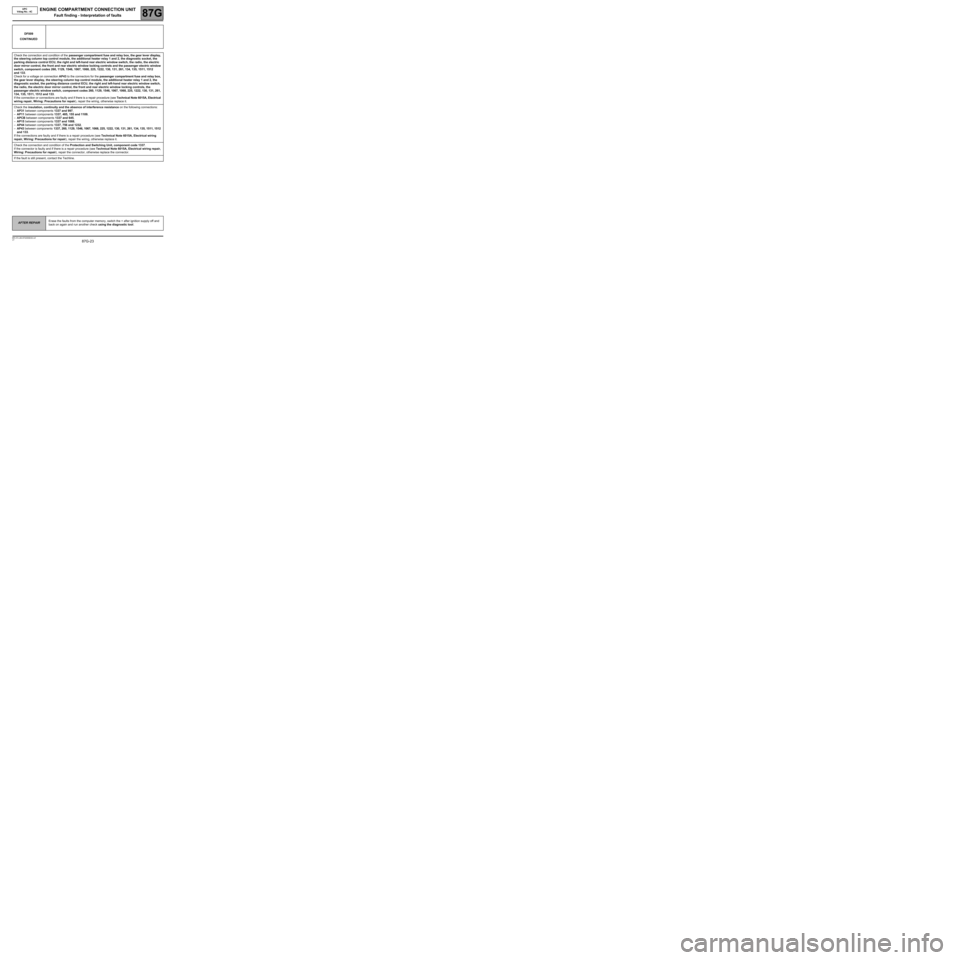
DF009
CONTINUED
Check the connection and condition of the passenger compartment fuse and relay box, the gear lever display,
the steering column top control module, the additional heater relay 1 and 2, the diagnostic socket, the
parking distance control ECU, the right and left-hand rear electric window switch, the radio, the electric
door mirror control, the front and rear electric window locking controls and the passenger electric window
switch, component codes 260, 1129, 1546, 1067, 1068, 225, 1222, 130, 131, 261, 134, 135, 1511, 1512
and 133.
Check for a voltage on connection AP43 to the connectors for the passenger compartment fuse and relay box,
the gear lever display, the steering column top control module, the additional heater relay 1 and 2, the
diagnostic socket, the parking distance control ECU, the right and left-hand rear electric window switch,
the radio, the electric door mirror control, the front and rear electric window locking controls, the
passenger electric window switch, component codes 260, 1129, 1546, 1067, 1068, 225, 1222, 130, 131, 261,
134, 135, 1511, 1512 and 133.
If the connection or connections are faulty and if there is a repair procedure (see Technical Note 6015A, Electrical
wiring repair, Wiring: Precautions for repair), repair the wiring, otherwise replace it.
Check the insulation, continuity and the absence of interference resistance on the following connections:
–AP31 between components 1337 and 997,
–AP11 between components 1337, 485, 155 and 1109,
–APCB between components 1337 and 645,
–AP15 between components 1337 and 1088,
–AP44 between components 1337, 756 and 1232,
–AP43 between components 1337, 260, 1129, 1546, 1067, 1068, 225, 1222, 130, 131, 261, 134, 135, 1511, 1512
and 133.
If the connections are faulty and if there is a repair procedure (see Technical Note 6015A, Electrical wiring
repair, Wiring: Precautions for repair), repair the wiring, otherwise replace it.
Check the connection and condition of the Protection and Switching Unit, component code 1337.
If the connector is faulty and if there is a repair procedure (see Technical Note 6015A, Electrical wiring repair,
Wiring: Precautions for repair), repair the connector, otherwise replace the connector.
If the fault is still present, contact the Techline.
AFTER REPAIRErase the faults from the computer memory, switch the + after ignition supply off and
back on again and run another check using the diagnostic tool.
Page 93 of 94

ENGINE COMPARTMENT CONNECTION UNIT
Fault finding - Tests87G
87G-93V7 MR-372-J84-87G050$935.mif
UPC
Vdiag No.: 48, 4C
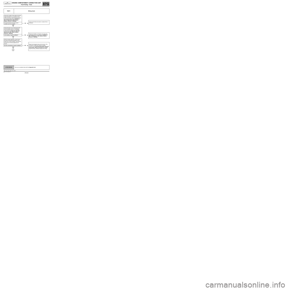
TEST1 Wiring check
Check the condition of the battery terminals.
Check that there is no corrosion on the
battery terminals. Check that the terminals
are correctly tightened (see MR 364 or
MR 370 Mechanical, 80A, Battery,
Battery: Removal - Refitting).
Clean the terminals and posts or replace them, if
necessary Are the terminals and posts in good
condition and not corroded?
Check that there are no electrolyte leaks
from the battery (cracks or breakage).
Check that the battery is correctly fitted
mechanically (see MR 364 or MR 370
Mechanical, 80A, Battery, Battery:
Removal - Refitting).
Replace the battery if necessary and clean the
surrounding area in the vehicle (see MR 364 or
MR 370 Mechanical, 80A, Battery, Battery:
Removal - Refitting). Is the battery in good condition?
With the engine stationary, check that all
the wires connecting the battery to the
starter are in good condition, and that their
terminals are correctly tightened and
secure.
Repair the damaged wires and terminals. If the
connection is faulty and if there is a repair
procedure (see Technical Note 6015A, Electrical
wiring repair, Wiring: Precautions for repair),
repair the wiring, otherwise replace the wiring. Are the connections in good condition?
NO
YES
NO
YES
NO
YES
A
AFTER REPAIRCarry out a complete check with the diagnostic tool.
USM_V48_TEST1/USM_V4C_TEST1