RENAULT SCENIC 2008 J84 / 2.G Gas Injection LPG 3000 Workshop Manual
Manufacturer: RENAULT, Model Year: 2008, Model line: SCENIC, Model: RENAULT SCENIC 2008 J84 / 2.GPages: 107, PDF Size: 0.31 MB
Page 1 of 107

1Engine and peripherals
V2 MR-372-J84-17C000$TOC.mif
V2
17C
"The repair procedures given by the manufacturer in this document are based on the
technical specifications current when it was prepared.
The procedures may be modified as a result of changes introduced by the
manufacturer in the production of the various component units and accessories from
which his vehicles are constructed."
V2
All rights reserved by Renault s.a.s.
Edition Anglaise
Copying or translating, in part or in full, of this document or use of the service part
reference numbering system is forbidden without the prior written authority of
Renault s.a.s.
© Renault s.a.s. 2008
GAS INJECTION
LPG 3000
Program No: AB
Vdiag No: 08/10
Fault finding - Introduction 17C - 2
Fault finding - System operation 17C - 9
Fault finding - Replacement of components 17C - 13
Fault finding - Configurations and programming 17C - 14
Fault finding - Fault summary table 17C - 15
Fault finding - Interpretation of faults 17C - 16
Fault finding - Conformity check 17C - 54
Fault finding - Status Summary table 17C - 76
Fault finding - Interpretation of statuses 17C - 77
Fault finding - Interpretation of parameters 17C - 83
Fault finding - Command summary table 17C - 89
Fault finding - Interpretation of commands 17C - 90
Fault finding - Customer complaints 17C - 98
Fault finding - Fault finding chart (ALP) 17C - 99
Page 2 of 107

17C-2
MR-372-J84-17C000$059.mif
V2
17C
GAS INJECTION
Fault finding - Introduction
1. SCOPE OF THIS DOCUMENT
This document presents the fault finding procedures applicable to all computers with the following specifications:
2. PREREQUISITES FOR FAULT FINDING
Documentation type
Fault finding procedures (this manual):
–Assisted fault finding (integrated into the diagnostic tool), Dialogys.
Wiring Diagrams:
–Visu-Schéma.
Type of diagnostic tools
–CLIP + multiplex line sensor
Special tooling required
3. REMINDERS
Procedure for Mégane 2
To carry out fault finding on the vehicle's computers, switch the ignition to fault finding mode (forced + after ignition).
Proceed as follows:
–Put the vehicle card in the card reader.
–Press and hold Start button (longer than 5 seconds) with start-up conditions not fulfilled.
–connect the diagnostic tool and perform the required operations.
To cut off the + after ignition feed, proceed as follows:
–disconnect the diagnostic tool,
–press the Start button twice briefly (less than 3 seconds),
–ensure that the + after ignition feed has been cut off by checking that the computer indicator lights on the
instrument panel have gone out.
Procedure for Logan
To run fault finding on the vehicle computers, switch on the ignition. Connect the diagnostic tool and perform the
required operations.Vehicle (s): LOGAN and MEGANE 2
Function concerned: Gas Injection
Engines: K4M 764/788/698Computer name: GAS 3000
Program No.: AB
Vdiag No.: 08/10
Special tooling required
Multimeter
Elé. 1681 Universal bornier
Note:
The left-hand and right-hand xenon bulb computers are powered when the dipped headlights are lit.
Fault finding on these computers is therefore not possible until after the ignition has been switched on in
diagnostic mode (forced + after ignition) and the dipped beam headlights have been switched on.
GAZ3000_V08_PRELI / GAZ3000_V10_PRELI
LPG 3000
Program No: AB
Vdiag No: 08/10
MR-372-J84-17C000$059.mif
Page 3 of 107

17C-3
MR-372-J84-17C000$059.mif
V2
GAS INJECTION
Fault finding - Introduction
LPG 3000
Program No: AB
Vdiag No: 08/10
17C
Faults
Faults are declared either present or stored (depending on whether they appeared in a certain situation and have
disappeared since, or whether they remain but have not been diagnosed within the current context).
The present or stored status of faults should be taken into consideration when the diagnostic tool is switched on
following + after ignition feed being activated (without any system components being active).
For a present fault, apply the procedure described in the Interpretation of faults section.
For a stored fault, note the faults displayed and apply the Notes section.
If the fault is confirmed when the instructions in the Notes section are applied, the fault is present. Deal with the
fault.
If the fault is not confirmed, check:
●the electrical lines which correspond to the fault,
●the connectors for these lines (for oxidation, bent pins, etc.),
●the resistance of the component detected as faulty,
●the condition of the wires (melted or split insulation, wear).
Conformity check
The aim of the conformity check is to check data that does not produce a fault on the diagnostic tool because the
data is inconsistent. Therefore, this phase makes it possible to:
●run fault finding on faults that do not have a fault display, and which may correspond to a customer complaint,
●check that the system is operating correctly and that there is no risk of a fault recurring after repairs.
This section gives the fault finding procedures for the statuses and the parameters and the conditions for checking
them.
If a status is not behaving normally or a parameter is outside the permitted tolerance values, consult the
corresponding fault finding page.
Customer complaints - Fault finding chart
If the test with the diagnostic tool is OK but the customer complaint is still present, the fault should be treated by
Customer complaints.
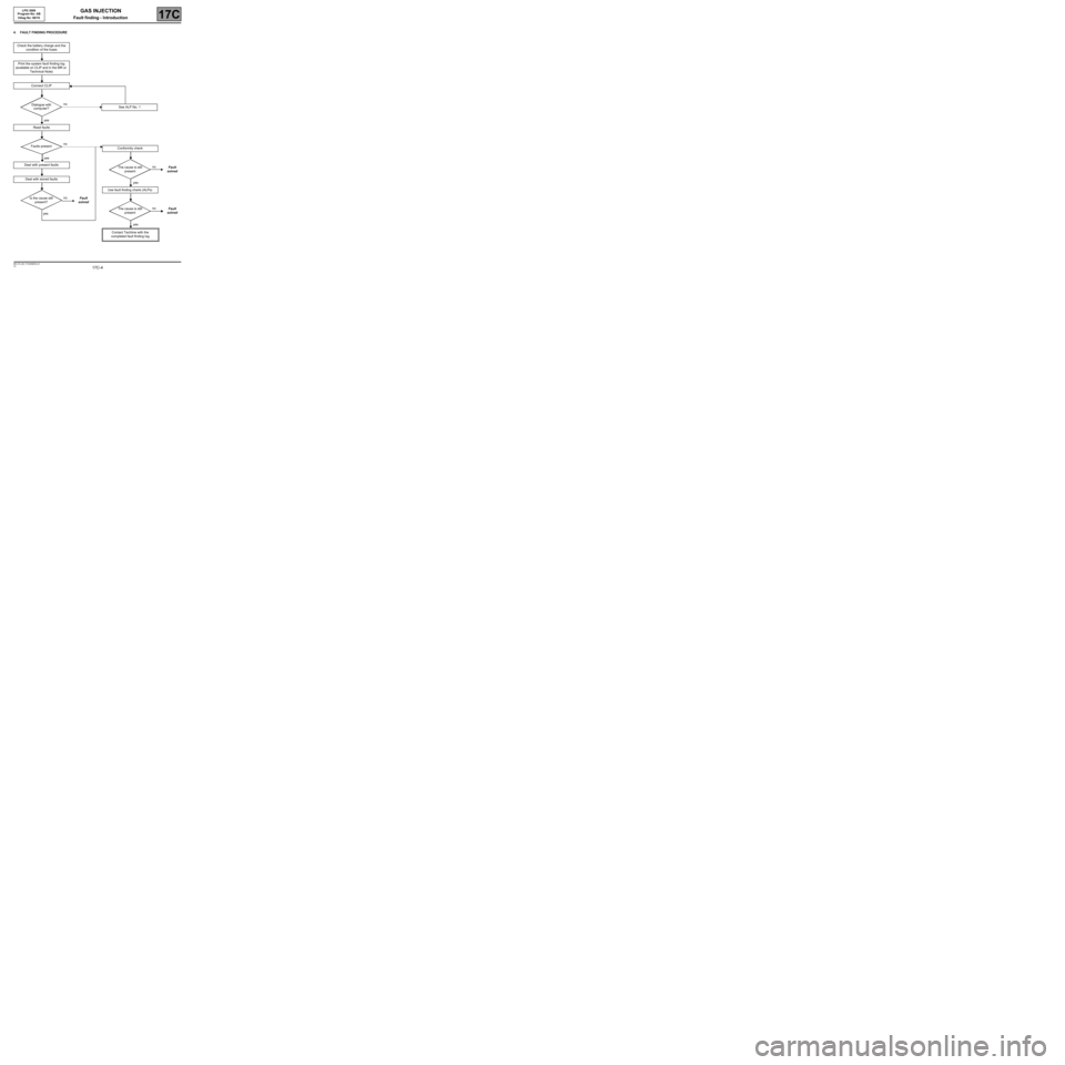
A summary of the overall procedure to follow is provided on the following page in the
form of a flow chart.
Page 4 of 107
17C-4
MR-372-J84-17C000$059.mif
V2
LPG 3000
Program No: AB
Vdiag No: 08/10GAS INJECTION
Fault finding - Introduction17C
4. FAULT FINDING PROCEDURE
Check the battery charge and the
condition of the fuses
Print the system fault finding log
(available on CLIP and in the MR or
Technical Note)
Connect CLIP
no
Dialogue with
computer?
yes
Read faults
no
Faults present
yes
Deal with present faults
Deal with stored faults
no
Is the cause still
present?Fault
solved
yes
See ALP No. 1
Conformity check
no
The cause is still
presentFault
solved
yes
Use fault finding charts (ALPs)
no
The cause is still
presentFault
solved
yes
Contact Techline with the
completed fault finding log
Page 5 of 107

17C-5
MR-372-J84-17C000$059.mif
V2
GAS INJECTION
Fault finding - Introduction
LPG 3000
Program No: AB
Vdiag No: 08/10
17C
4. FAULT FINDING PROCEDURE (continued)
Wiring check
Fault finding problems
Disconnecting the connectors and/or manipulating the wiring harness may temporarily remove the cause of a fault.
Electrical measurements of voltage, resistance and insulation are generally correct, especially if the fault is not
present when the analysis is made (stored fault).
Visual inspection
●look for damaged wiring under the bonnet and in the passenger compartment.
●carefully check the fuses, insulation and the correct routing of the wiring.
●look for signs of oxidation.
Tactile inspection
While manipulating the wiring harness, use the diagnostic tool to note any change in fault status from stored to
present.
●Make sure that the connectors are properly locked.
●Apply light pressure to the connectors.
●Twist the wiring harness.
If there is a change in status, try to locate the source of the fault.
Inspection of each component
●disconnect the connectors and check the appearance of the clips and tabs, as well as the crimping (no
crimping on the insulating section).
●make sure that the clips and tabs are properly locked in the sockets.
●Check that no clips or tabs have been dislodged during connection.
●check the clip contact pressure using an appropriate model of tab.
Resistance check
●check the continuity of the entire lines, then section by section.
●look for a short circuit to earth, to + 12V or with another wire.
If a fault is detected, apply the associated fault finding procedure and repair or replace the wiring.
Page 6 of 107

17C-6
MR-372-J84-17C000$059.mif
V2
GAS INJECTION
Fault finding - Introduction
LPG 3000
Program No: AB
Vdiag No: 08/10
17C
2. FAULT FINDING LOG
You will always be asked for this log:
–when requesting technical assistance from the Techline,
–for approval requests when replacing parts for which approval is obligatory,
–to be enclosed when returning monitored parts on request. The log is needed for warranty reimbursement,
and enables better analysis of the parts which have been removed.
5. SAFETY INSTRUCTIONS
Safety rules must be observed during any work on a component to prevent any damage or injury:
–make sure that the battery is properly charged to avoid damaging the computers with a low charge,
–use the appropriate tools.
Safety instructions that must be followed before any operation is performed on the vehicle
–If a major LPG leak occurs, the vehicle must be isolated, away from buildings and any fire risks.
–the emergency services may be required to intervene if the situation cannot be controlled.
–all work on the LPG circuit must be performed by qualified and authorised personnel,
–do not try to open the tank. Never try to remove the multi-valve located at the end of the tank.
–do not clean the engine compartment using a pressure system with detergents.
–always refer to the RENAULT Workshop Repair Manual before performing any work.
Safety instructions that must be followed when any operation is performed on the vehicle
–all work must be carried out in a well-ventilated space,
–there must not be any naked flames, sparks, lit cigarettes or telephones near the area where work is being
carried out,
–the operator must not wear acrylic clothes likely to generate static electricity.
–disconnect the battery and leave the vehicle on the ground,
–if working on the tank, drain it by running the engine in LPG mode,
–once drained and removed, the tank can be sent to GIAT, complete with its mounting,
–if work is to be done in the spray booth, remove the tank (with its mounting),
–the tank must not be subjected to temperatures greater than 50°C. IMPORTANTIMPORTANT
Any fault on a complex system must undergo a thorough fault finding procedure with the
appropriate tools. The FAULT FINDING LOG, which should be completed during the fault finding
procedure, ensures a record is kept of the procedure carried out. It is an essential component
when consulting the manufacturer.
IT IS THEREFORE MANDATORY TO FILL OUT A FAULT FINDING LOG EVERY TIME
THE TECHLINE OR THE WARRANTY RETURN SERVICE ASKS FOR IT.
Page 7 of 107

17C-7
MR-372-J84-17C000$059.mif
V2
GAS INJECTION
Fault finding - Introduction
LPG 3000
Program No: AB
Vdiag No: 08/10
17C
Safety instructions that must be followed after any operation is performed on the vehicle
–after working on an LPG union, check that it is not leaking after it has been refitted,
–apply soapy water or the product distributed by SODICAM, part number 77 11 143 071 (leak detector) to the
open union(s),
–fill the fuel tank with a few litres of LPG if it has been bled (the ignition must be switched off first),
–start the engine, put it in LPG mode and check again that there is no leak,
–if a leak is detected, retighten the union concerned. If the leak persists, refit the union,
–fill the fuel tank (80% of the total volume). start the engine, put it in LPG mode and check that there is no leak,
–after refitting, check that all the rubber and encased steel LPG pipes are not in contact with any parts that may
cause them to wear and create an LPG leak.
Page 8 of 107

17C-8
MR-372-J84-17C000$059.mif
V2
GAS INJECTION
Fault finding - Introduction
LPG 3000
Program No: AB
Vdiag No: 08/10
17C
ROAD TEST (in Petrol mode, then in LPG mode)
–check that the stabilisation time is normal,
–check that the engine does not stall under sudden braking and that it maintains a stable idle speed until the vehicle
comes to a stop,
–put the vehicle in 4th gear, at a steady speed of 36 mph (60 km/h). Check that the vehicle accelerates
progressively under full load acceleration.
Maintenance operations:
–no adjustment,
–removal of internal components is not permitted,
–if LPG clips are removed, they must be replaced,
–if LPG unions are removed, they must be replaced.
The tank must be bled before removing:
●the fuel tank,
●a component bolted to the fuel tank,
To remove the following, bleed all gas contained in the gas circuit (except the gas in the tank):
●the filler neck,
●the pipes,
●the filter,
●the pressure relief valve,
●the solenoid valve. IMPORTANT
Before performing any work on the vehicle, drain the LPG circuit.
Only personnel who have undergone special LPG training can work with gas unions where gas is circulating and
which run from the expansion valve via the fuel tank.
Equally, only these persons are permitted to perform servicing and repair operations on LPG vehicles.
Workshops can only carry out work on the fuel tank if they have a degassing burner. If the tank cannot be
degassed, do not carry out any work and contact the Comité Français du Butane et du Propane (French
Butane and Propane Commission) by fax on 01 41 97 02 89.
Page 9 of 107

17C-9
MR-372-J84-17C000$118.mif
V2
17C
GAS INJECTION
Fault finding - System operation
1. System operation:
Composition
–The LPG injection system consists of the:
–LPG tank,
–fuel sender,
–overpressure unit (thermally triggered),
–LPG solenoid valve relay,
–tank solenoid valve,
–reducer (LPG) or expansion valve (CNG),
–expansion valve,
–filling spigot or socket,
–LPG hose,
–tank pressure sensor,
–LPG pipes,
–unions,
–airtight cover,
–regulator valve or anti-return valve,
–excess pressure valve,
–LPG filter,
–temperature and pressure sensor,
–LPG computer,
–LPG expansion solenoid valve,
–gas injectors,
–LPG or petrol selection switch,
–fuel sender relay,
–LPG tank relay,
–fuel pump cut-off relay.
Operating principle
The GAS 3000 computer electronically manages the operation of the LPG systems (Liquefied Petroleum Gas) and
CNG (Compressed Natural Gas).
The engine must be started in Petrol mode. The vehicle will automatically switch to "Gas" mode after starting if the
"gas" configuration was selected beforehand. "Petrol" mode switches to "gas" mode after a certain time delay, which
depends on the engine coolant temperature.
Petrol mode operates autonomously. Information is shared between the Petrol computer and the LPG computer via
a CAN connection.
The K line shared by the two computers allows diagnostics to be run on both the petrol and the LPG systems.
The Petrol computer is also the supervisor of the LPG system and includes, in addition to petrol-specific functions,
functions for adapting engine management programming to LPG operation.
Therefore, the Petrol computer includes settings and variables that are specific for LPG operation, e.g. ignition
advance adjustment in LPG mode, LPG flow rate setting, richness regulation, engine operating mode, etc.
It controls the choice of program (petrol start-up etc.) and controls the transition phases for switching from one
operating mode to the other: Petrol → Gas or Gas → Petrol. The fuel pump is regularly supplied to keep the system
under pressure in the event of a possible return to "Petrol" mode (if the "Gas" tank is detected as empty or if a fault
is detected).
LPG 3000
Program No: AB
Vdiag No: 08/10
MR-372-J84-17C000$118.mif
Page 10 of 107

17C-10
MR-372-J84-17C000$118.mif
V2
GAS INJECTION
Fault finding - System operation
LPG 3000
Program No: AB
Vdiag No: 08/10
17C
The GAS 3000 computer manages "gas" actuator control, i.e. the "gas" injectors, the gas system relays and solenoid
valves, the fuel pump cut-off relay and the management of the fuel sender. Before switching to "Gas" mode, the
computer always checks that the pressure and the temperature of the gas are correct and that the "gas" solenoid
valves are open.
The combustible material is stored in an independent toric tank. LPG is stored in a semi-gaseous state at a pressure
of approximately 15 bar.
CNG is stored in a cylindrical tank in a gaseous state at a pressure of approximately 200 bar, and is transported to
the expansion valve/reducer via a rigid high pressure pipe. The rest of the system is a low pressure pipe going from
the expansion valve/reducer to the injectors. For CNG, there is a gas filter between the expansion valve and the rail.
Malfunctions / Special cases
These are characterised by operation in Petrol mode, although the driver has selected LPG mode.
An operational fault must be caused by the LPG system if it cannot be reproduced in Petrol mode.
Forced Petrol mode when LPG is faulty.
The level 1 warning light is controlled by the petrol injection computer; the gas warning light is controlled by the GAS
3000 computer.
The system automatically switches to "petrol" mode when the tank is empty or when the conditions allowing
operation in "gas" mode are not satisfied.