compressor RENAULT SCENIC 2008 J84 / 2.G Engine Compartment Connection Unit Workshop Manual
[x] Cancel search | Manufacturer: RENAULT, Model Year: 2008, Model line: SCENIC, Model: RENAULT SCENIC 2008 J84 / 2.GPages: 94, PDF Size: 0.28 MB
Page 10 of 94
ENGINE COMPARTMENT CONNECTION UNIT
Fault finding - System operation87G
87G-10V7 MR-372-J84-87G050$110.mif
UPC
Vdiag No.: 48, 4C
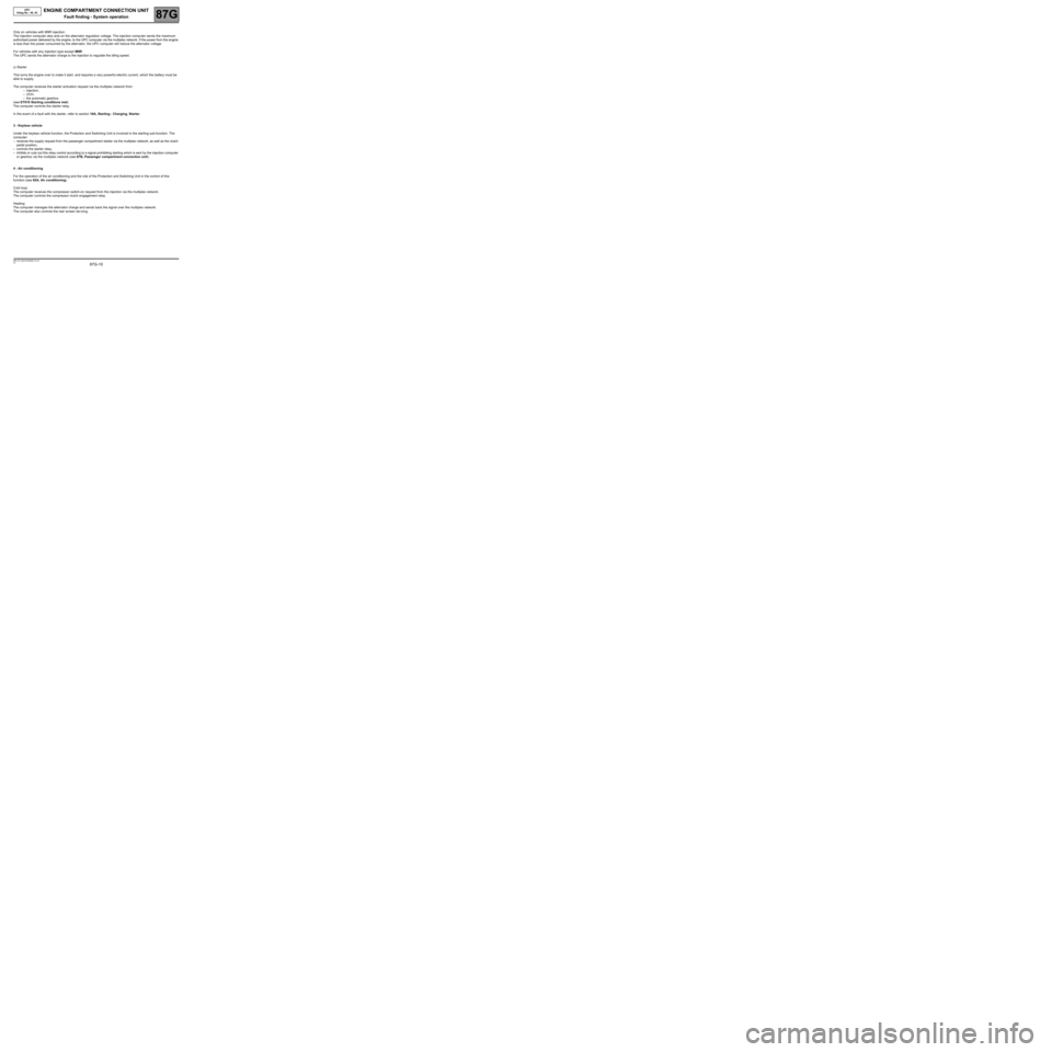
Only on vehicles with M9R injection:
The injection computer also acts on the alternator regulation voltage. The injection computer sends the maximum
authorised power delivered by the engine, to the UPC computer via the multiplex network. If the power from the engine
is less than the power consumed by the alternator, the UPC computer will reduce the alternator voltage.
For vehicles with any injection type except M9R:
The UPC sends the alternator charge to the injection to regulate the idling speed.
c) Starter
This turns the engine over to make it start, and requires a very powerful electric current, which the battery must be
able to supply.
The computer receives the starter activation request via the multiplex network from:
–injection,
–UCH,
–the automatic gearbox.
(see ET010 Starting conditions met)
The computer controls the starter relay.
In the event of a fault with the starter, refer to section 16A, Starting - Charging, Starter.
3 - Keyless vehicle
Under the keyless vehicle function, the Protection and Switching Unit is involved in the starting sub-function. The
computer:
–receives the supply request from the passenger compartment starter via the multiplex network, as well as the clutch
pedal position,
–controls the starter relay,
–inhibits or cuts out this relay control according to a signal prohibiting starting which is sent by the injection computer
or gearbox via the multiplex network (see 87B, Passenger compartment connection unit).
4 - Air conditioning
For the operation of the air conditioning and the role of the Protection and Switching Unit in the control of this
function (see 62A, Air conditioning).
Cold loop:
The computer receives the compressor switch-on request from the injection via the multiplex network.
The computer controls the compressor clutch engagement relay.
Heating:
The computer manages the alternator charge and sends back the signal over the multiplex network.
The computer also controls the rear screen de-icing.
Page 12 of 94
ENGINE COMPARTMENT CONNECTION UNIT
Fault finding - System operation87G
87G-12V7 MR-372-J84-87G050$110.mif
UPC
Vdiag No.: 48, 4C
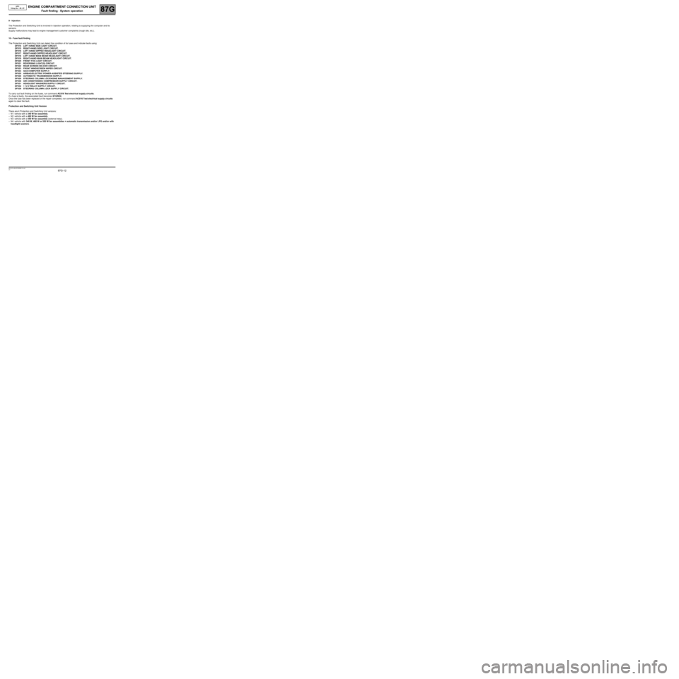
9 - Injection
The Protection and Switching Unit is involved in injection operation, relating to supplying the computer and its
sensors.
Supply malfunctions may lead to engine management customer complaints (rough idle, etc.).
10 - Fuse fault finding
The Protection and Switching Unit can detect the condition of its fuses and indicate faults using:
DF014 LEFT-HAND SIDE LIGHT CIRCUIT.
DF015 RIGHT-HAND SIDE LIGHT CIRCUIT.
DF016 LEFT-HAND DIPPED HEADLIGHT CIRCUIT.
DF017 RIGHT-HAND DIPPED HEADLIGHT CIRCUIT.
DF018 LEFT-HAND MAIN BEAM HEADLIGHT CIRCUIT.
DF019 RIGHT-HAND MAIN BEAM HEADLIGHT CIRCUIT.
DF020 FRONT FOG LIGHT CIRCUIT.
DF021 REVERSING LIGHT(S) CIRCUIT.
DF022 REAR SCREEN DE-ICER CIRCUIT.
DF023 FRONT WINDSCREEN WIPER CIRCUIT.
DF024 GAS COMPUTER SUPPLY.
DF025 AIRBAG/ELECTRIC POWER-ASSISTED STEERING SUPPLY.
DF026 AUTOMATIC TRANSMISSION SUPPLY.
DF029 STEERING COLUMN LOC/ENGINE MANAGEMENT SUPPLY.
DF030 AIR CONDITIONING COMPRESSOR SUPPLY CIRCUIT.
DF031 HEADLIGHT WASHERS SUPPLY CIRCUIT.
DF032 + 12 V RELAY SUPPLY CIRCUIT.
DF036 STEERING COLUMN LOCK SUPPLY CIRCUIT.
To carry out fault finding on the fuses, run command AC016 Test electrical supply circuits.
If a fuse is faulty, the associated fault becomes STORED.
Once the fuse has been replaced or the repair completed, run command AC016 Test electrical supply circuits
again to clear the fault.
Protection and Switching Unit Version
There are 4 Protection and Switching Unit versions:
–N1: vehicle with a 340 W fan assembly.
–N2: vehicle with a 460 W fan assembly.
–N3: vehicle with a 550 W fan assembly (external relay).
–N4: vehicle with 340 W, 460 W or 550 W fan assemblies + automatic transmission and/or LPG and/or with
headlight washers.
Page 15 of 94
ENGINE COMPARTMENT CONNECTION UNIT
87G
87G - 15V7 MR-372-J84-87G050$275.mif
UPC
Vdiag No.: 48, 4CENGINE COMPARTMENT CONNECTION UNIT
Fault finding - Fault summary table
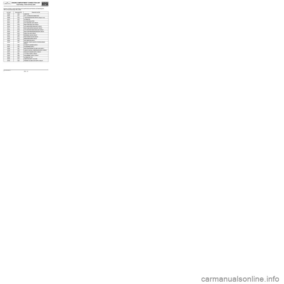
Summary of faults on which fault finding can be performed by the Protection and Switching Unit.
(With corresponding design office codes).
Tool fault Associated DTC Diagnostic tool title
DF006 920E COMPUTER
DF007 9211 UPC - ALTERNATOR CONNECTION
DF009 9214 + AFTER IGNITION FEED CIRCUIT (Vdiag 4C only)
DF012 9210 ALTERNATOR
DF013 920F VOLTAGE REGULATION
DF014 9217 LEFT-HAND SIDE LIGHT CIRCUIT
DF015 9218 RIGHT-HAND SIDE LIGHT CIRCUIT
DF016 9215 LEFT-HAND DIPPED HEADLIGHT CIRCUIT
DF017 9216 RIGHT-HAND DIPPED HEADLIGHT CIRCUIT
DF018 921B LEFT-HAND MAIN BEAM HEADLIGHT CIRCUIT
DF019 921C RIGHT-HAND MAIN BEAM HEADLIGHT CIRCUIT
DF020 921D FRONT FOG LIGHT CIRCUIT
DF021 9226 REVERSING LIGHT(S) CIRCUIT
DF022 921E REAR SCREEN DE-ICER CIRCUIT
DF023 921A WINDSCREEN WIPER CIRCUIT
DF024 9222 GAS COMPUTER SUPPLY
DF025 9223 ELECTRIC POWER ASSISTED STEERING/AIRBAG
SUPPLY
DF026 9224 AUTOMATIC GEARBOX SUPPLY
DF027 9225 ACCESSORIES SUPPLY
DF029 9221 INJECTION/STEERING COLUMN LOCK SUPPLY
DF030 9219 CLIMATE CONTROL COMPRESSOR SUPPLY CIRCUIT
DF031 921F HEADLIGHT WASHER SUPPLY CIRCUIT
DF032 9227 +12 V RELAY SUPPLY CIRCUIT
DF033 9229 FAN ASSEMBLY SUPPLY CIRCUIT
DF034 9212 ALTERNATOR TYPE
DF035 9213 COMPUTER SUPPLY VOLTAGE
DF036 9220 STEERING COLUMN LOCK SUPPLY CIRCUIT
MR-372-J84-87G050$275.mif
Page 49 of 94
ENGINE COMPARTMENT CONNECTION UNIT
Fault finding - Interpretation of faults87G
87G - 49V7 MR-372-J84-87G050$385.mif
UPC
Vdiag No.: 48, 4C
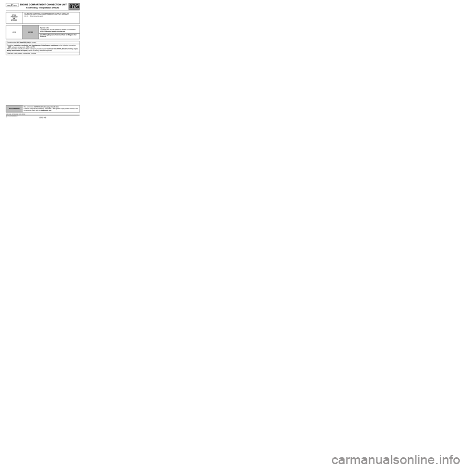
DF030
PRESENT
OR
STOREDCLIMATE CONTROL COMPRESSOR SUPPLY CIRCUIT
CC.0 : Short circuit to earth
CC.0
NOTESSpecial note:
To display this fault as present or stored, run command
AC016 Electrical supply circuits test.
Use Wiring Diagrams Technical Note for Mégane II or
Scénic II.
Check that the UPC fuse F22 (10A) is correct.
Check the insulation, continuity and the absence of interference resistance on the following connection:
–38R, between components 1337 and 171.
If the connection is faulty and there is a repair procedure (see Technical Note 6015A, Electrical wiring repair,
Wiring: Precautions for repair), repair the wiring, otherwise replace it.
If the fault is still present, contact the Techline.
AFTER REPAIRRun command AC016 Electrical supply circuits test.
Clear the computer fault memory, switch the + after ignition supply off and back on, and
run another check with the diagnostic tool.
USM_V48_DF030/USM_V4C_DF030
Page 59 of 94
ENGINE COMPARTMENT CONNECTION UNIT
Fault finding - Conformity check87G
87G-59V7 MR-372-J84-87G050$440.mif
UPC
Vdiag No.: 48, 4C
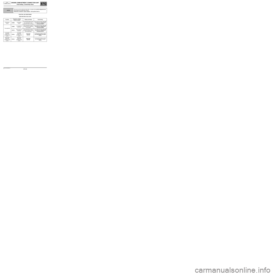
FUNCTION: AIR CONDITIONING
SUB-FUNCTION: COLD LOOP
NOTESOnly carry out this conformity check after a complete check with the diagnostic tool
(fault reading and configuration checks).
Application conditions: engine stopped, + after ignition feed on.
FunctionParameter or Status
Check or ActionDisplay and Notes Fault finding
Compressor
controlAC008:Compressor
controlYou should be able to hear
the compressor clutch
(stops the motor running).In the event of a fault, apply the
procedure for dealing with
command AC008.
Fan assemblyAC009:Low-speed fan
assemblyThis command is used to
activate the fan assembly
at low speed.In the event of a fault, apply the
procedure for dealing with
command AC009.
AC010:High-speed fan
assemblyThis command is used to
activate the engine cooling
fan at high speed.In the event of a fault, apply the
procedure for dealing with
command AC010.
Low-speed
engine fan
assembly relay
controlET014:Low-speed
engine fan
assembly relay
controlINACTIVE
ACTIVEIn the event of a fault, consult
the interpretation for status
ET014.
High-speed
engine fan
assembly relay
controlET013:High-speed
engine fan
assembly relay
controlINACTIVE
ACTIVEIn the event of a fault, consult
the interpretation for status
ET013.
Page 75 of 94
ENGINE COMPARTMENT CONNECTION UNIT
Fault finding - Command summary table87G
87G - 75V7 MR-372-J84-87G050$715.mif
UPC
Vdiag No.: 48, 4CENGINE COMPARTMENT CONNECTION UNIT
Fault finding - Command summary table
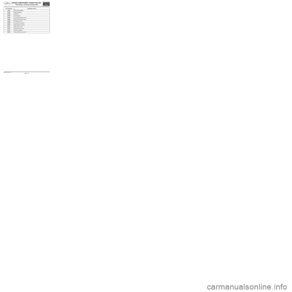
Tool command Diagnostic tool title
AC001Main beam headlights
AC002Dipped headlights
AC003Side lights
AC004Front fog lights
AC005Low-speed windscreen wiper
AC006High-speed windscreen wiper
AC008Compressor control
AC009Low-speed fan assembly
AC010High-speed fan assembly
AC011Rear screen de-icer
AC013Headlight washers relay
AC014Alternator regulation
AC016Test electrical supply circuits
MR-372-J84-87G050$715.mif
Page 82 of 94
ENGINE COMPARTMENT CONNECTION UNIT
Fault finding - Interpretation of commands87G
87G - 82V7 MR-372-J84-87G050$770.mif
UPC
Vdiag No.: 48, 4C
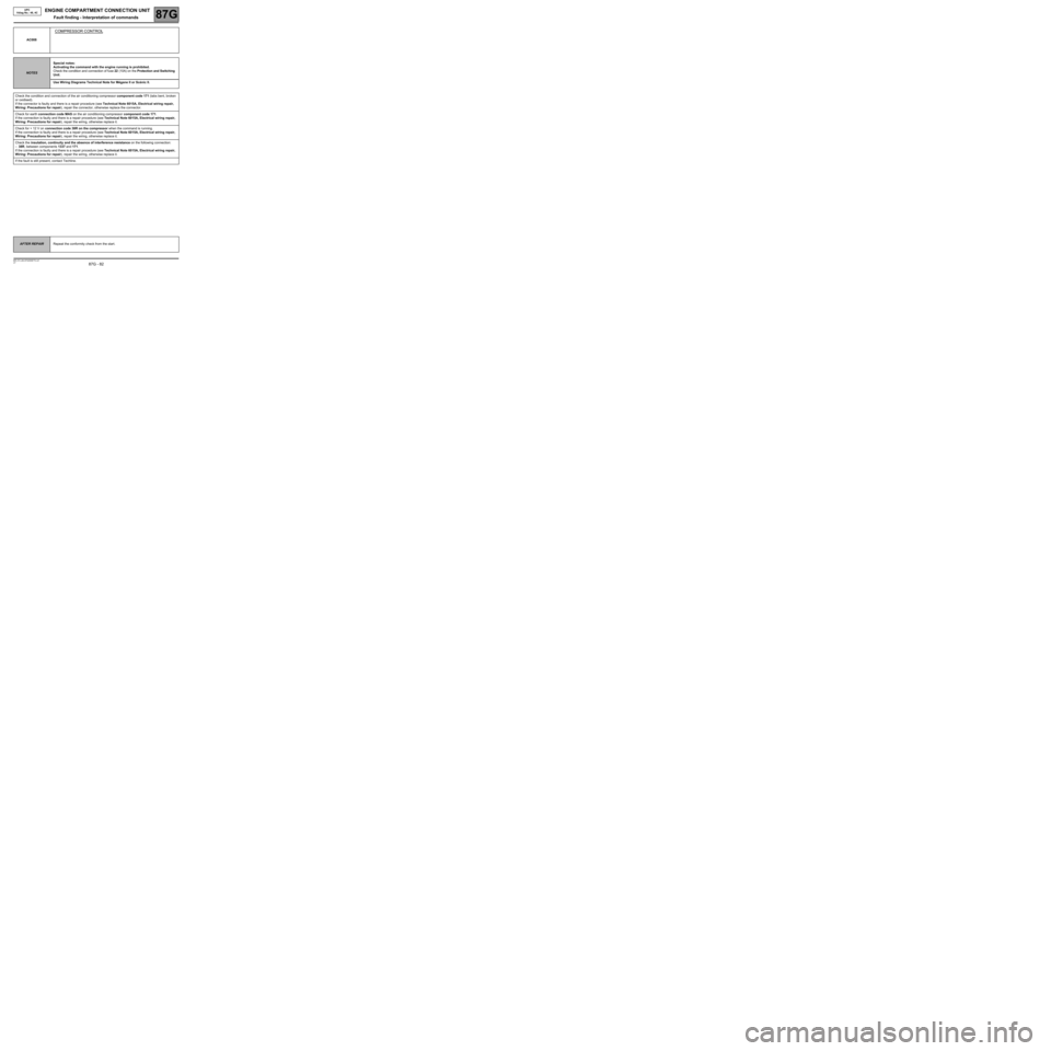
AC008
COMPRESSOR CONTROL
NOTESSpecial notes:
Activating the command with the engine running is prohibited.
Check the condition and connection of fuse 22 (10A) on the Protection and Switching
Unit.
Use Wiring Diagrams Technical Note for Mégane II or Scénic II.
Check the condition and connection of the air conditioning compressor component code 171 (tabs bent, broken
or oxidised).
If the connector is faulty and there is a repair procedure (see Technical Note 6015A, Electrical wiring repair,
Wiring: Precautions for repair), repair the connector, otherwise replace the connector.
Check for earth connection code MAS on the air conditioning compressor component code 171.
If the connection is faulty and there is a repair procedure (see Technical Note 6015A, Electrical wiring repair,
Wiring: Precautions for repair), repair the wiring, otherwise replace it.
Check for + 12 V on connection code 38R on the compressor when the command is running.
If the connection is faulty and there is a repair procedure (see Technical Note 6015A, Electrical wiring repair,
Wiring: Precautions for repair), repair the wiring, otherwise replace it.
Check the insulation, continuity and the absence of interference resistance on the following connection:
–38R, between components 1337 and 171.
If the connection is faulty and there is a repair procedure (see Technical Note 6015A, Electrical wiring repair,
Wiring: Precautions for repair), repair the wiring, otherwise replace it.
If the fault is still present, contact Techline.
AFTER REPAIRRepeat the conformity check from the start.