air condition RENAULT SCENIC 2008 J84 / 2.G Passenger Comparment Connection Unit Workshop Manual
[x] Cancel search | Manufacturer: RENAULT, Model Year: 2008, Model line: SCENIC, Model: RENAULT SCENIC 2008 J84 / 2.GPages: 391
Page 334 of 391
PASSENGER COMPARTMENT CONNECTION UNIT
Fault finding - Fault Finding Chart87B
87B - 334
PASSENGER COMPARTMENT CONNECTION UNIT
Fault finding - Fault Finding Chart87B
87B - 334V9 MR-372-J84-87B000$946.mif
UCH
Vdiag No.: 44, 48,
4C, 4D, 4F, 50
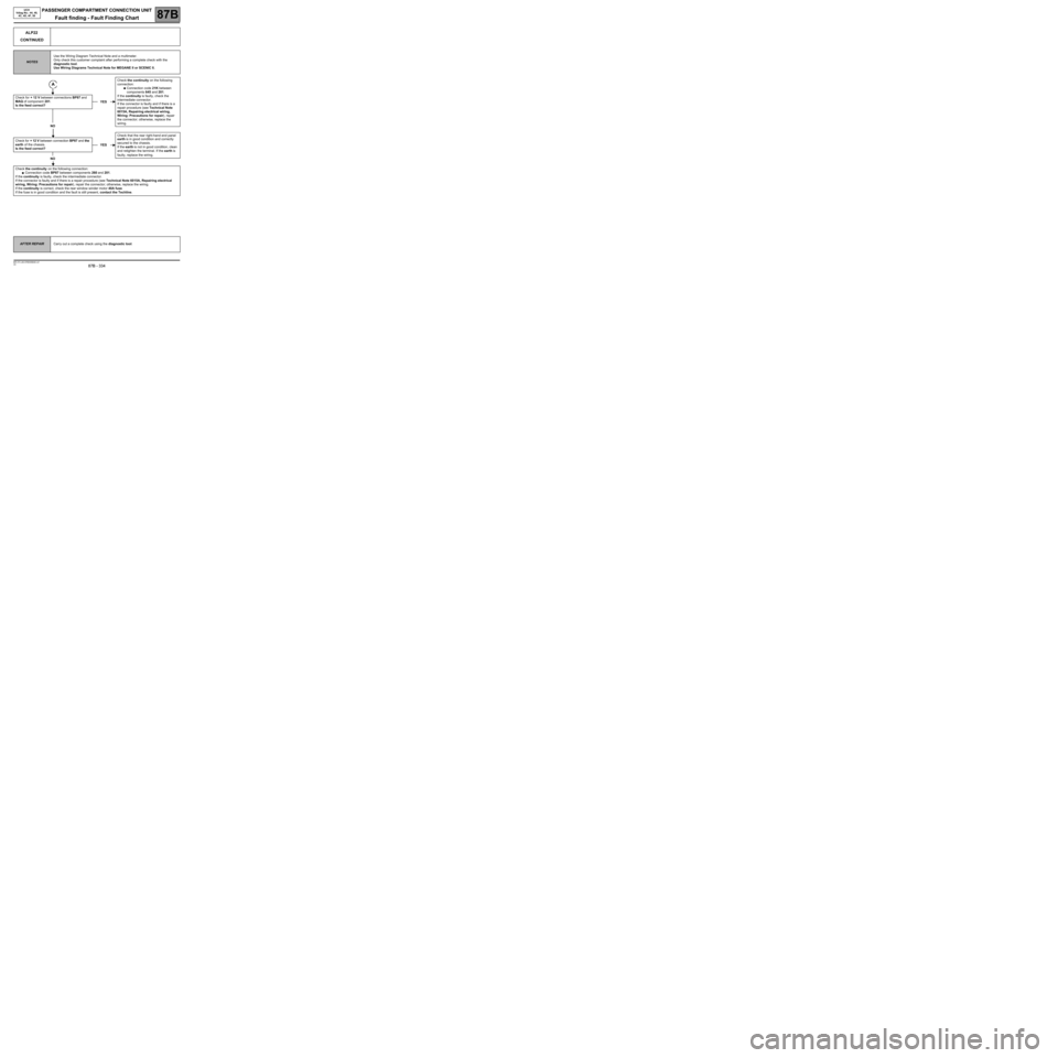
ALP22
CONTINUED
NOTESUse the Wiring Diagram Technical Note and a multimeter.
Only check this customer complaint after performing a complete check with the
diagnostic tool.
Use Wiring Diagrams Technical Note for MEGANE II or SCENIC II.
Check for + 12 V between connections BP87 and
MAQ of component 201.
Is the feed correct?
NO
Check for + 12 V between connection BP87 and the
earth of the chassis.
Is the feed correct?
NO
Check the continuity on the following connection:
●Connection code BP87 between components 260 and 201.
If the continuity is faulty, check the intermediate connector.
If the connector is faulty and if there is a repair procedure (see Technical Note 6015A, Repairing electrical
wiring, Wiring: Precautions for repair), repair the connector; otherwise, replace the wiring.
If the continuity is correct, check the rear window winder motor 40A fuse.
If the fuse is in good condition and the fault is still present, contact the Techline.
YESCheck the continuity on the following
connection:
●Connection code 21K between
components 645 and 201.
If the continuity is faulty, check the
intermediate connector.
If the connector is faulty and if there is a
repair procedure (see Technical Note
6015A, Repairing electrical wiring,
Wiring: Precautions for repair), repair
the connector; otherwise, replace the
wiring.
YESCheck that the rear right-hand end panel
earth is in good condition and correctly
secured to the chassis.
If the earth is not in good condition, clean
and retighten the terminal. If the earth is
faulty, replace the wiring.
AFTER REPAIRCarry out a complete check using the diagnostic tool.
Page 335 of 391
PASSENGER COMPARTMENT CONNECTION UNIT
Fault finding - Fault Finding Chart87B
87B - 335
PASSENGER COMPARTMENT CONNECTION UNIT
Fault finding - Fault Finding Chart87B
87B - 335V9 MR-372-J84-87B000$946.mif
UCH
Vdiag No.: 44, 48,
4C, 4D, 4F, 50
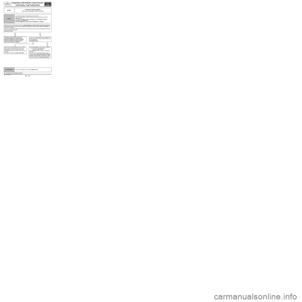
ALP23No electric window operation
(Driver's and passengers' electric windows)
NOTESUse the Wiring Diagram Technical Note and a multimeter.
Only check this customer complaint after performing a complete check with the
diagnostic tool.
For vehicles with Mégane II phase 2 bodywork, see 87D Electric windows -
Sunroof, Fault finding chart.
Use Wiring Diagrams Technical Note for MEGANE II or SCENIC II.
Remove the driver's window winder switch (see MR 364 (Mégane) or MR 370 (Scenic) Mechanical systems,
87D, Electric windows - Sunroof, Front window winder switch on driver's door: Removal - Refitting) and
disconnect its connector.
Check for + 12 V between track 5 of the driver's window winder switch white connector and track 4 of the driver's
window winder black connector.
Is the feed correct?
YES NO
Replace the driver's electric window switch
(see MR 364 (Mégane) or MR 370 (Scenic)
Mechanical systems, 87D, Electric windows -
Sunroof, Front electric window switch on
driver's door: Removal - Refitting).
Check that the left-hand dashboard cross member
earth is in good condition and secured correctly.
If the earth is not in good condition, clean and
retighten the terminal. If the earth is faulty, replace
the wiring.
If the fault is still present, contact the Techline.
Check for + 12 V between connection track 5 of the
driver's window winder switch white connector and
the chassis earth.
Is the feed correct?
YES NO
Check the continuity on the following connection:
●Connection code 21K between
components 203 and 645.
If the continuity is faulty, check the intermediate
connector.
If the connector is faulty and if there is a repair
procedure (see Technical Note 6015A, Repairing
electrical wiring, Wiring: Precautions for repair),
repair the connector; otherwise, replace the wiring.
If the fault is still present, contact the Techline.
AFTER REPAIRCarry out a complete check using the diagnostic tool.
UCH_V44_ALP23 /UCH_V48_ALP23/UCH_V4C_ALP23/
UCH_V4D_ALP23/UCH_V4F_ALP23/UCH_V50_ALP23
Page 339 of 391

PASSENGER COMPARTMENT CONNECTION UNIT
Fault finding - Fault Finding Chart87B
87B - 339
PASSENGER COMPARTMENT CONNECTION UNIT
Fault finding - Fault Finding Chart87B
87B - 339V9 MR-372-J84-87B000$946.mif
UCH
Vdiag No.: 44, 48,
4C, 4D, 4F, 50
ALP24
CONTINUED 3
Disconnect the black connector from the sunroof motor.
Using a multimeter, check for + 12 V between connections BP93 and MAM of component 304.
Is the feed correct?
YESNO
Replace the sunroof motor (see 87D Electric windows - sunroof: Removal - Refitting).
Using the wiring diagram which corresponds to the vehicle, check the conformity of union R301.
Disconnect the sunroof motor connector (see MR Mechanical systems, 87D Electric windows-sunroof,
Sunroof motor: Removal - Refitting) and disconnect union R301.
Check the continuity of the following connections:
●Connection code MAM.
●Connection code BP93 between components 304 and R301.
If the continuity is faulty, check the intermediate connector R339.
If one of the connectors is faulty and there is a repair procedure (see Technical Note 6015A, Electrical wiring
repair, Wiring: Precautions for repair), repair the connector, otherwise replace the wiring.
After repairing the condition of the wiring, initialise the sunroof (see MR fault finding 87D, Electric sunroof:
Initialisation).
If the fault is still present, contact the Techline.
AFTER REPAIRCarry out a complete check using the diagnostic tool.
Page 340 of 391

PASSENGER COMPARTMENT CONNECTION UNIT
Fault finding - Fault Finding Chart87B
87B - 340
PASSENGER COMPARTMENT CONNECTION UNIT
Fault finding - Fault Finding Chart87B
87B - 340V9 MR-372-J84-87B000$946.mif
UCH
Vdiag No.: 44, 48,
4C, 4D, 4F, 50
ALP24
CONTINUED 4
Is the control correct?
YES
Disconnect the sunroof motor connector (see MR Mechanical, 87D Electric windows - sunroof, Sunroof motor:
Removal - Refitting).
Check for + 12 V between connections BP93 and MAM of component 304.
Is the feed correct?
YESNO
Using the wiring diagram which corresponds to the vehicle, check the conformity of union R301.
Disconnect the sunroof motor connector (see MR Mechanical systems, 87D Electric windows-
sunroof, Sunroof motor: Removal - Refitting) and disconnect union R301.
Check the continuity of the following connections:
●Connection code MAM.
●Connection code BP93 between components 304 and R301.
If the continuity is faulty, check the intermediate connector R339.
If one of the connectors is faulty and there is a repair procedure (see Technical Note 6015A,
Electrical wiring repair, Wiring: Precautions for repair), repair the connector, otherwise
replace the wiring.
After repairing the condition of the wiring, initialise the sunroof (see MR fault finding 87D, Electric
sunroof: Initialisation).
If the fault is still present, contact the Techline.
NOReplace the control (see MR Mechanical
systems, 87D Electric windows -
sunroof, Sunroof switch: Removal -
Refitting).
AFTER REPAIRCarry out a complete check using the diagnostic tool.
Page 341 of 391
PASSENGER COMPARTMENT CONNECTION UNIT
Fault finding - Fault Finding Chart87B
87B - 341
PASSENGER COMPARTMENT CONNECTION UNIT
Fault finding - Fault Finding Chart87B
87B - 341V9 MR-372-J84-87B000$946.mif
UCH
Vdiag No.: 44, 48,
4C, 4D, 4F, 50
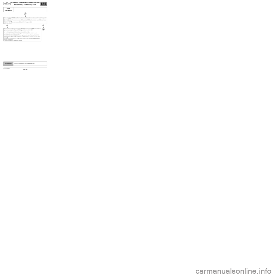
ALP24
CONTINUED 5
Check using status ET087 Sunroof/one touch window authorisation that authorisation for the UCH to open the
sunroof is ACTIVE.
Disconnect the sunroof motor connector (see MR Mechanical, 87D Electric windows - sunroof, Sunroof motor:
Removal - Refitting).
Check for + 12 V between connections BP93 and 21K of component 304.
Is the feed correct?
NOYES
Disconnect the sunroof motor connector (see MR Mechanical systems, 87D Electric windows-
sunroof, Sunroof motor: Removal - Refitting) and disconnect union R301.
Check the continuity on the following connection:
●Connection code 21K between components 304 and 645.
If the continuity is faulty, use the wiring diagram corresponding to the vehicle to check
intermediate connectors R339 and R301.
If one of the connectors is faulty and there is a repair procedure (see Technical Note 6015A,
Electrical wiring repair, Wiring: Precautions for repair), repair the connector, otherwise replace
the wiring.
After repairing the condition of the wiring, initialise the sunroof (see MR fault finding 87D, Electric
sunroof: Initialisation).
If the fault is still present, contact the Techline.
AFTER REPAIRCarry out a complete check using the diagnostic tool.
Page 342 of 391
PASSENGER COMPARTMENT CONNECTION UNIT
Fault finding - Fault Finding Chart87B
87B - 342
PASSENGER COMPARTMENT CONNECTION UNIT
Fault finding - Fault Finding Chart87B
87B - 342V9 MR-372-J84-87B000$946.mif
UCH
Vdiag No.: 44, 48,
4C, 4D, 4F, 50
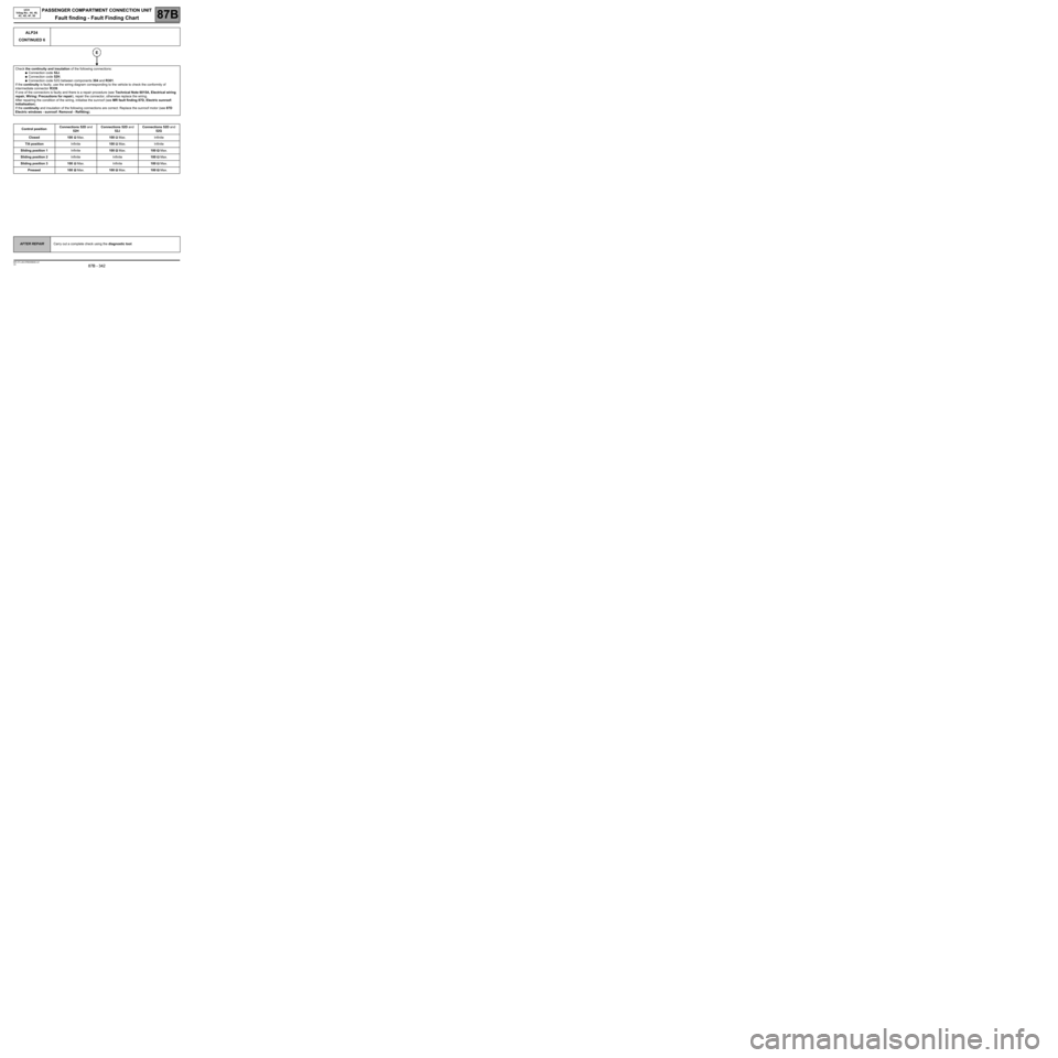
ALP24
CONTINUED 6
Check the continuity and insulation of the following connections:
●Connection code 52J.
●Connection code 52H.
●Connection code 52G between components 304 and R301.
If the continuity is faulty, use the wiring diagram corresponding to the vehicle to check the conformity of
intermediate connector R339.
If one of the connectors is faulty and there is a repair procedure (see Technical Note 6015A, Electrical wiring
repair, Wiring: Precautions for repair), repair the connector, otherwise replace the wiring.
After repairing the condition of the wiring, initialise the sunroof (see MR fault finding 87D, Electric sunroof:
Initialisation).
If the continuity and insulation of the following connections are correct: Replace the sunroof motor (see 87D
Electric windows - sunroof: Removal - Refitting).
Control positionConnections 52D and
52HConnections 52D and
52JConnections 52D and
52G
Closed 100 ΩΩ Ω Ω
Max.100 ΩΩ Ω Ω
Max. Infinite
Tilt position Infinite100 ΩΩ Ω Ω
Max. Infinite
Sliding position 1Infinite100 ΩΩ Ω Ω
Max.100 ΩΩ Ω Ω
Max.
Sliding position 2Infinite Infinite100 ΩΩ Ω Ω
Max.
Sliding position 3 100 ΩΩ Ω Ω
Max. Infinite100 ΩΩ Ω Ω
Max.
Pressed 100 ΩΩ Ω Ω
Max.100 ΩΩ Ω Ω
Max.100 ΩΩ Ω Ω
Max.
AFTER REPAIRCarry out a complete check using the diagnostic tool.
Page 344 of 391
PASSENGER COMPARTMENT CONNECTION UNIT
Fault finding - Fault Finding Chart87B
87B - 344
PASSENGER COMPARTMENT CONNECTION UNIT
Fault finding - Fault Finding Chart87B
87B - 344V9 MR-372-J84-87B000$946.mif
UCH
Vdiag No.: 44, 48,
4C, 4D, 4F, 50
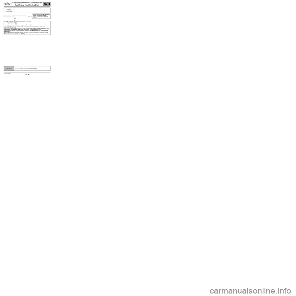
ALP25
CONTINUED
Is the control correct?
YES
Check the continuity and insulation of the following connections:
●Connection code 52J.
●Connection code 52H.
●Connection code 52G between components 304 and R301.
If the continuity is faulty, use the wiring diagram corresponding to the vehicle to check the conformity of
intermediate connector R339.
If one of the connectors is faulty and there is a repair procedure (see Technical Note 6015A, Electrical wiring
repair, Wiring: Precautions for repair), repair the connector, otherwise replace the wiring.
After repairing the condition of the wiring, initialise the sunroof (see MR fault finding 87D, Electric sunroof:
Initialisation).
If the continuity and insulation of the following connections are correct: Replace the sunroof motor (see 87D
Electric windows - sunroof: Removal - Refitting).
NOReplace the control (see MR Mechanical
systems, 87D Electric windows -
sunroof, Sunroof switch: Removal -
Refitting).
AFTER REPAIRCarry out a complete check using the diagnostic tool.
Page 347 of 391
PASSENGER COMPARTMENT CONNECTION UNIT
Fault finding - Fault Finding Chart87B
87B - 347
PASSENGER COMPARTMENT CONNECTION UNIT
Fault finding - Fault Finding Chart87B
87B - 347V9 MR-372-J84-87B000$946.mif
UCH
Vdiag No.: 44, 48,
4C, 4D, 4F, 50
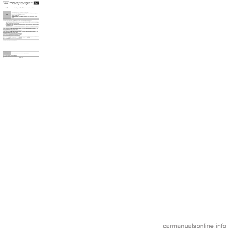
ALP27 Locking/unlocking fault when pressing card button.
NOTESCheck that there is no APC or card in the card reader.
Check that no opening element is detected as open by the UCH (look at the symbol on
the instrument panel).
First carry out a function fault finding check.
Test with the other card.
Check the condition of the battery (inserted the wrong way round, flat, incorrect
model).
If the fault is still present after having carried out a test with the other card, it could be that:
–There may be radiofrequency interference in the area (ET066 Card button press received is NO for both
cards). Move the vehicle to try again.
–The UCH which has just been replaced does not have the correct part number (external or internal UCH
aerial). Use the correct UCH part number.
–If the vehicle is a Scenic II fitted with a tyre pressure monitoring system, check that the external UCH aerial
is connected correctly.
–Check that the UCH for the vehicle is not blank. Check that the UCH on the vehicle has not been used on
another vehicle.
Check that statuses ET066 Card button press received and ET067 Card button press recognised are YES
after pressing the card's lock or unlock button.
If not, apply the fault finding procedures for those statuses.
Check that statuses ET066 Card button press received and ET067 Card button press recognised are YES
after pressing the card's lock or unlock button.
If not, apply the fault finding procedures for those statuses.
Check that status ET014 Control power level is not APC.
If not, apply the fault finding procedures for this status.
Check that statuses ET041 Opening rear screen, ET042 Passenger's door, ET050 Tailgate/Boot, ET051 Rear
left-hand door, ET052 Rear left-hand door and ET053 Driver's door are CLOSED.
If not, apply the fault finding procedures for those statuses.
If the fault is still present, contact Techline.
AFTER REPAIRCarry out a complete check using the diagnostic tool.
UCH_V44_ALP27 /UCH_V48_ALP27/UCH_V4C_ALP27/
UCH_V4D_ALP27/UCH_V4F_ALP27/UCH_V50_ALP27
Page 348 of 391
PASSENGER COMPARTMENT CONNECTION UNIT
Fault finding - Fault Finding Chart87B
87B - 348
PASSENGER COMPARTMENT CONNECTION UNIT
Fault finding - Fault Finding Chart87B
87B - 348V9 MR-372-J84-87B000$946.mif
UCH
Vdiag No.: 44, 48,
4C, 4D, 4F, 50
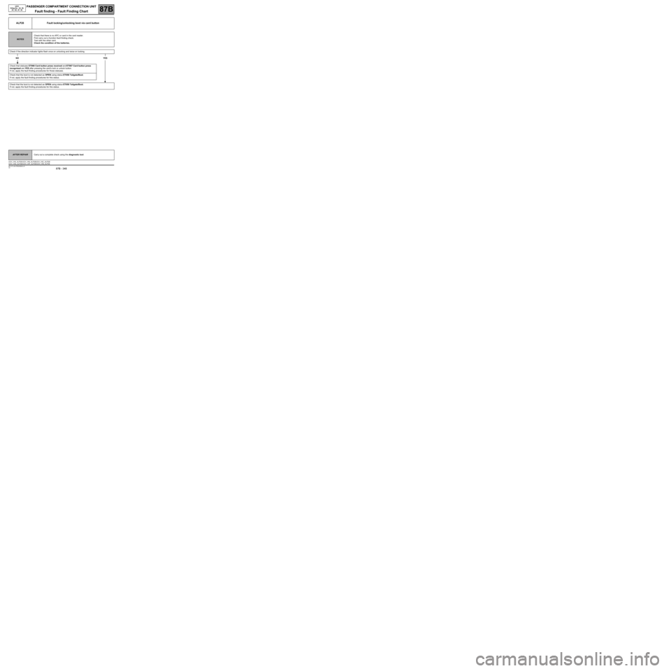
ALP28 Fault locking/unlocking boot via card button
NOTESCheck that there is no APC or card in the card reader.
First carry out a function fault finding check.
Test with the other card.
Check the condition of the batteries.
Check if the direction indicator lights flash once on unlocking and twice on locking.
NOYES
Check that statuses ET066 Card button press received and ET067 Card button press
recognised are YES after pressing the card's lock or unlock button.
If not, apply the fault finding procedures for those statuses.
Check that the boot is not detected as OPEN using status ET050 Tailgate/Boot.
If not, apply the fault finding procedures for this status.
Check that the boot is not detected as OPEN using status ET050 Tailgate/Boot.
If not, apply the fault finding procedures for this status.
AFTER REPAIRCarry out a complete check using the diagnostic tool.
UCH_V44_ALP28 /UCH_V48_ALP28/UCH_V4C_ALP28/
UCH_V4D_ALP28/UCH_V4F_ALP28/UCH_V50_ALP28
Page 351 of 391
PASSENGER COMPARTMENT CONNECTION UNIT
Fault finding - Fault Finding Chart87B
87B - 351
PASSENGER COMPARTMENT CONNECTION UNIT
Fault finding - Fault Finding Chart87B
87B - 351V9 MR-372-J84-87B000$946.mif
UCH
Vdiag No.: 44, 48,
4C, 4D, 4F, 50
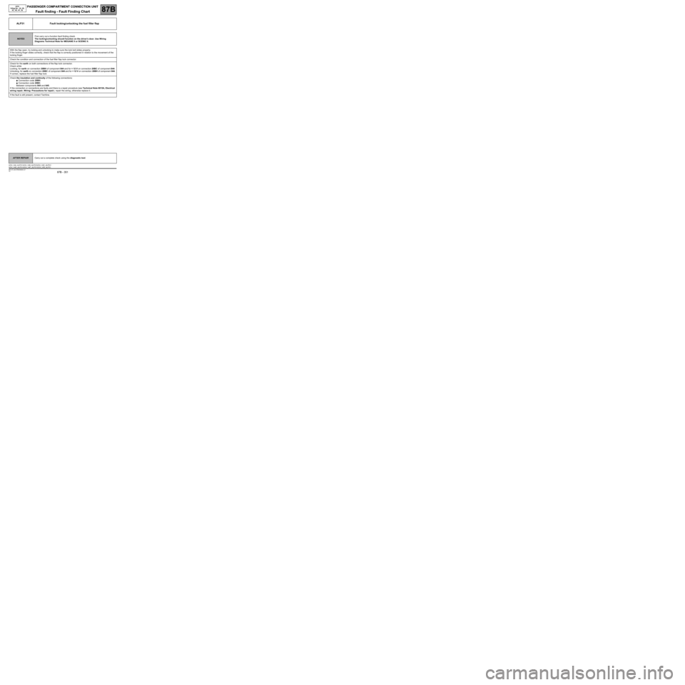
ALP31 Fault locking/unlocking the fuel filler flap
NOTESFirst carry out a function fault finding check.
The locking/unlocking should function on the driver's door. Use Wiring
Diagrams Technical Note for MEGANE II or SCENIC II.
With the flap open, try locking and unlocking to make sure the lock bolt slides properly.
If the locking finger slides correctly, check that the flap is correctly positioned in relation to the movement of the
locking finger.
Check the condition and connection of the fuel filler flap lock connector.
Check for the earth on both connections of the flap lock connector.
Check while:
Locking, for earth on connection 20BH of component 844 and for + 12 V on connection 20BC of component 844.
Unlocking, for earth on connection 20BC of component 844 and for + 12 V on connection 20BH of component 844.
If correct, replace the fuel filler flap lock.
Check the insulation and continuity of the following connections:
●Connection code 20BH.
●Connection code 20BC.
Between components 844 and 645.
If the connection or connections are faulty and there is a repair procedure (see Technical Note 6015A, Electrical
wiring repair, Wiring: Precautions for repair), repair the wiring, otherwise replace it.
If the fault is still present, contact Techline.
AFTER REPAIRCarry out a complete check using the diagnostic tool.
UCH_V44_ALP31 /UCH_V48_ALP31/UCH_V4C_ALP31/
UCH_V4D_ALP31/UCH_V4F_ALP31/UCH_V50_ALP31