fuse diagram RENAULT SCENIC 2008 J84 / 2.G Passenger Comparment Connection Unit Workshop Manual
[x] Cancel search | Manufacturer: RENAULT, Model Year: 2008, Model line: SCENIC, Model: RENAULT SCENIC 2008 J84 / 2.GPages: 391
Page 80 of 391
PASSENGER COMPARTMENT CONNECTION UNIT
Fault finding - Interpretation of faults
87B
87B-80
PASSENGER COMPARTMENT CONNECTION UNIT
Fault finding - Interpretation of faults
87B
87B-80V9 MR-372-J84-87B000$301.mif
UCH
Vdiag No.: 44, 48,
4C, 4D, 4F, 50
DF011
PRESENT
OR
STOREDRAIN/LIGHT SENSOR CIRCUIT
1.DEF: Communication disrupted
2.DEF: Internal electronic fault
NOTESConditions for applying the fault finding procedure to a stored fault:
Run the automatic wiper system and automatic light illumination system, then cover the
sensor and/or place water on it.
If the fault appears, carry out this fault finding procedure.
Use Wiring Diagrams Technical Note for MEGANE II or SCENIC II.
1.DEF
NOTESNone.
For vehicles which were manufactured after June 2005, check the condition and connection of the sensor supply
7.5A fuse located on the Protection and Switching Unit.
Replace it if necessary.
Check the condition and connection of the sensor connector (bent, oxidised, broken tabs etc.).
If the connector is faulty and there is a repair procedure (see Technical Note 6015A, Electrical wiring repair,
Wiring: Precautions for repair), repair the connector, otherwise replace the wiring.
Check for an earth on connection MAM of component 1415.
If the connector is faulty and if there is a repair method (see Technical Note 6015A, Repairing electrical wiring,
Wiring: Precautions for repair), repair the connector; otherwise, replace the wiring.
Check for + 12 V, BPT connection of component 1415 (timed + 12 V before ignition feed if the vehicle was
manufactured after June 2005). If the connection is faulty and if there is a repair procedure (see Technical Note
6015A, Electrical wiring repair, Wiring: Precautions for repair), repair the wiring, otherwise replace the wiring.
Ensure the continuity and the insulation of the following connection:
●Connection code BPT between components 645 and 1415.
If the connection is faulty and if there is a repair procedure (see Technical Note 6015A, Electrical wiring repair,
Wiring: Precautions for repair), repair the wiring, otherwise replace the wiring.
Check for any intermediate connectors using the vehicle wiring diagram and repair if necessary.
AFTER REPAIRCarry out another fault finding check on the system.
Clear the stored faults.
Deal with any other faults.
UCH_V44_DF011/UCH_V48_DF011/UCH_V4C_DF011/
UCH_V4D_DF011/UCH_V4F_DF011 /UCH_V50_DF011
Page 103 of 391
PASSENGER COMPARTMENT CONNECTION UNIT
Fault finding - Interpretation of faults
87B
87B -103
PASSENGER COMPARTMENT CONNECTION UNIT
Fault finding - Interpretation of faults
87B
87B -103V9 MR-372-J84-87B000$344.mif
UCH
Vdiag No.: 44, 48,
4C, 4D, 4F, 50
DF030
PRESENT
ANTI-LOCKING LINE
CO: Open circuit
NOTESUse Wiring Diagrams Technical Note for MEGANE II or SCENIC II.
CO.1
NOTESNone.
Check the condition and connection of the steering column lock connector (tabs bent, broken).
If the connector is faulty and if there is a repair method (see Technical Note 6015A, Repairing electrical wiring,
Wiring: Precautions for repair), repair the connector; otherwise, replace the wiring.
Check the presence and condition of the F5D fuse on the UPC (Vdiag 44 UPC) or the F18 fuse (Vdiag 48 UPC
or later). Replace the fuse if it is faulty.
Check the condition and connection of connector PEH (UPC Vdiag 44) or connector CT1 (UPC Vdiag 48) of the
UPC (bent or broken tabs, etc.).
If the connector is faulty and if there is a repair method (see Technical Note 6015A, Repairing electrical wiring,
Wiring: Precautions for repair), repair the connector; otherwise, replace the wiring.
Check the insulation and continuity of the following connection:
●Connection code AP15 between components 645 and 1088.
If the connection is faulty and there is a repair procedure (see Technical Note 6015A, Electrical wiring repair,
Wiring: Precautions for repair), repair the wiring, otherwise replace it.
If the fault is still present, contact the Techline.
AFTER REPAIRCarry out another fault finding check on the system.
Clear the stored faults.
Deal with any other faults.
UCH_V44_DF030P/UCH_V48_DF030P/UCH_V4C_DF030P/
UCH_V4D_DF030P/UCH_V4F_DF030P/UCH_V50_DF030P
Page 169 of 391
PASSENGER COMPARTMENT CONNECTION UNIT
Fault finding - Interpretation of statuses
87B
87B -169
PASSENGER COMPARTMENT CONNECTION UNIT
Fault finding - Interpretation of statuses
87B
87B -169V9 MR-372-J84-87B000$473.mif
UCH
Vdiag No.: 44, 48,
4C, 4D, 4F, 50
ET047
CONTINUED 3
ET047 Undetermined with the pedal depressed.
Check the condition and connection of the brake pedal switch connector.
If the connector is faulty and if there is a repair method (see Technical Note 6015A, Repairing electrical wiring,
Wiring: Precautions for repair), repair the connector; otherwise, replace the wiring.
With the brake pedal switch disconnected:
Check for + 12 V on component 160 on connection SP17.
If not correct:
–Check the condition and connection of fuse 1H in the passenger compartment relay and fuse box.
–Check the condition and the connection of the passenger compartment fuse and relay box connector. If the
connector is faulty and if there is a repair method (see Technical Note 6015A, Repairing electrical wiring,
Wiring: Precautions for repair), repair the connector; otherwise, replace the wiring.
–Check the insulation and continuity of connection SP17 between components 160 and 260. If the connection
is faulty and there is a repair procedure (see Technical Note 6015A, Electrical wiring repair, Wiring:
Precautions for repair), repair the wiring, otherwise replace it.
If it is still faulty, contact Techline.
With the brake pedal switch disconnected:
Check the continuity of the following connections:
●Connection code 65A,
●Connection code SP17 of component 160 (brake pedal switch piston free).
Only replace the brake pedal switch if it is not correct.
Check the condition and connection of the UCH connector PE2.
If the connector is faulty and if there is a repair method (see Technical Note 6015A, Repairing electrical wiring,
Wiring: Precautions for repair), repair the connector; otherwise, replace the wiring.
With the UCH and brake pedal switch disconnected:
Check the insulation and continuity of the following connection:
●Connection code 65A between components 645 and 160.
If the connection is faulty and there is a repair procedure (see Technical Note 6015A, Electrical wiring repair,
Wiring: Precautions for repair), repair the wiring, otherwise replace it.
The line is shared with the ABS computer or the ESP relay (depending on equipment) and the brake lights. In the
event of faulty insulation, it is therefore necessary, using a wiring diagram, to check the connections between the
brake pedal switch connector and these components.
AFTER REPAIRCarry out another fault finding check on the system.
Clear the stored faults.
Deal with any other faults.
Page 192 of 391
PASSENGER COMPARTMENT CONNECTION UNIT
Fault finding - Interpretation of statuses87B
87B - 192
PASSENGER COMPARTMENT CONNECTION UNIT
Fault finding - Interpretation of statuses87B
87B - 192V9 MR-372-J84-87B000$516.mif
UCH
Vdiag No.: 44, 48,
4C, 4D, 4F, 50
ET075
+ ACCESSORIES PRESENT
NOTESNo faults should be present or stored.
Special note:
Check that the start switch operates correctly: ET070 Start button.
Use Wiring Diagrams Technical Note for MEGANE II or SCENIC II.
ET075 is YES but + accessories is absent.
Check for + 12 V on component 260 (on the left-hand side of the centre console) on connection BP11 (track E1).
If the connector is faulty and if there is a repair procedure (see Technical Note 6015A, Repairing electrical
wiring, Wiring: Precautions for repair), repair the connector; otherwise, replace the wiring.
Check the power-supply fuses.
Check that there is no + 12 V on connection S of component 645 (with + after ignition feed).
If NO, contact the techline.
If YES, check the continuity of the following connection:
●Connection code S between components 645 and 260.
If the connection is faulty and there is a repair procedure (see Technical Note 6015A, Electrical wiring repair,
Wiring: Precautions for repair), repair the wiring, otherwise replace it.
AFTER REPAIRCarry out another fault finding check on the system.
Clear the stored faults.
Deal with any other faults.
UCH_V44_ET075/UCH_V48_ET075/ UCH_V4C_ET075/
UCH_V4D_ET075 /UCH_V4F_ET075/UCH_V50_ET075
Page 211 of 391
PASSENGER COMPARTMENT CONNECTION UNIT
Fault finding - Interpretation of statuses87B
87B - 211
PASSENGER COMPARTMENT CONNECTION UNIT
Fault finding - Interpretation of statuses87B
87B - 211V9 MR-372-J84-87B000$559.mif
UCH
Vdiag No.: 44, 48,
4C, 4D, 4F, 50
ET085
HAZARD WARNING LIGHTS BUTTON
NOTESNo faults should be present or stored.
Use Wiring Diagrams Technical Note for MEGANE II or SCENIC II.
ET085 is Absent with button pressed.
Check the F16 15A fuse of the passenger compartment fuse and relay box on the left-hand side of the centre
console.
Replace it if necessary.
Check the door/warning switch connector (e.g.: connector properly connected, tabs bent, broken, oxidised).
If the connector is faulty and if there is a repair procedure (see Technical Note 6015A, Repairing electrical
wiring, Wiring: Precautions for repair), repair the connector; otherwise, replace the wiring.
Check the PE2 and PE1 connectors (e.g. connector properly connected, tabs bent, broken, oxidised).
If the connector is faulty and if there is a repair procedure (see Technical Note 6015A, Repairing electrical
wiring, Wiring: Precautions for repair), repair the connector; otherwise, replace the wiring.
Check for + 12 V on connection LPG of component 1391.
If the connector is faulty and if there is a repair procedure (see Technical Note 6015A, Repairing electrical
wiring, Wiring: Precautions for repair), repair the connector; otherwise, replace the wiring.
Check the insulation and continuity of the following connections:
●Connection code 64F.
●Connection code 64Q between components 645 and 1391.
If the connection or connections are faulty and there is a repair procedure (see Technical Note 6015A, Electrical
wiring repair, Wiring: Precautions for repair), repair the wiring, otherwise replace it.
Check the following connections on component 1391 (button pressed):
●Connection code 64F.
●Connection code 64Q.
If there is insulation, replace the button.
If there is continuity, contact the techline.
AFTER REPAIRCarry out another fault finding check on the system.
Clear the stored faults.
Deal with any other faults.
UCH_V44_ET085/UCH_V48_ET085/ UCH_V4C_ET085/
UCH_V4D_ET085 /UCH_V4F_ET085/UCH_V50_ET085
Page 232 of 391
PASSENGER COMPARTMENT CONNECTION UNIT
Fault finding - Interpretation of statuses87B
87B - 232
PASSENGER COMPARTMENT CONNECTION UNIT
Fault finding - Interpretation of statuses87B
87B - 232V9 MR-372-J84-87B000$559.mif
UCH
Vdiag No.: 44, 48,
4C, 4D, 4F, 50
ET114
WIPER REQUEST BY RAIN SENSOR
NOTESNo faults should be present or stored.
Make sure that the vehicle is fitted with the rain and light sensor.
The status should change to ACTIVE if there is any water on the windscreen on the
sensor position.
Make sure that the other positions of the wiper control are working properly.
Use Wiring Diagrams Technical Note for MEGANE II or SCENIC II.
Check the condition and connection of the rain and light sensor connector (tabs broken, bent, oxidised).
If the connector is faulty and if there is a repair procedure (see Technical Note 6015A, Repairing electrical
wiring, Wiring: Precautions for repair), repair the connector; otherwise, replace the wiring.
Check the + 12 V APC on connection BPT of component 1415.
If the connector is faulty and if there is a repair procedure (see Technical Note 6015A, Repairing electrical
wiring, Wiring: Precautions for repair), repair the connector; otherwise, replace the wiring.
If the + 12 V feed is not correct, check the insulation, continuity and the absence of interference resistance
of the following connection:
●Connection code BPT between components 645 and 1415.
If the connection is faulty and there is a repair procedure (see Technical Note 6015A, Electrical wiring repair,
Wiring: Precautions for repair), repair the wiring, otherwise replace it.
If the + 12 V feed is not correct for vehicles manufactured after June 2005, check the insulation, continuity and
the absence of interference resistance on the following connection:
●Connection code BPT between component 645 and fuse F5F (7.5A) (on the Protection and Switching
Unit).
Check for earth on the MAM connection of component 1415.
If the connector is faulty and if there is a repair procedure (see Technical Note 6015A, Repairing electrical
wiring, Wiring: Precautions for repair), repair the connector; otherwise, replace the wiring.
Check the condition and connection of the UCH connector (tabs broken, bent, oxidised).
If the connector is faulty and if there is a repair procedure (see Technical Note 6015A, Repairing electrical
wiring, Wiring: Precautions for repair), repair the connector; otherwise, replace the wiring.
Check the insulation, continuity and the absence of interference resistance on the following connection:
●Connection code 14S between components 645 and 1415.
If the connection is faulty and there is a repair procedure (see Technical Note 6015A, Electrical wiring repair,
Wiring: Precautions for repair), repair the wiring, otherwise replace it.
Check configuration LC044 Rain/light sensor.
If the fault is still present, contact Techline.
AFTER REPAIRCarry out another fault finding check on the system.
Clear the stored faults.
Deal with any other faults.
UCH_V44_ET114/UCH_V48_ET114/UCH_V4C_ET114/
UCH_V4D_ET114/UCH_V4F_ET114/UCH_V50_ET114
Page 233 of 391
PASSENGER COMPARTMENT CONNECTION UNIT
Fault finding - Interpretation of statuses87B
87B - 233
PASSENGER COMPARTMENT CONNECTION UNIT
Fault finding - Interpretation of statuses87B
87B - 233V9 MR-372-J84-87B000$559.mif
UCH
Vdiag No.: 44, 48,
4C, 4D, 4F, 50
ET115
REQUEST FROM LIGHT SENSOR TO SWITCH ON HEADLIGHTS
NOTESNo faults should be present or stored.
Make sure that the vehicle is fitted with the rain and light sensor.
The status should change to ACTIVE when the sensor is hidden from the surrounding
light by placing a thumb over it or in darkness.
Make sure that the other lighting control positions are working properly.
Use Wiring Diagrams Technical Note for MEGANE II or SCENIC II.
Check the condition and connection of the rain and light sensor connector (tabs broken, bent, oxidised).
If the connector is faulty and if there is a repair procedure (see Technical Note 6015A, Repairing electrical
wiring, Wiring: Precautions for repair), repair the connector; otherwise, replace the wiring.
Check the + 12 V APC on connection BPT of component 1415.
If the connector is faulty and if there is a repair procedure (see Technical Note 6015A, Repairing electrical
wiring, Wiring: Precautions for repair), repair the connector; otherwise, replace the wiring.
If the + 12 V feed is not correct, check the insulation, continuity and the absence of interference resistance
of the following connection:
●Connection code BPT between components 645 and 1415.
If the connection is faulty and there is a repair procedure (see Technical Note 6015A, Electrical wiring repair,
Wiring: Precautions for repair), repair the wiring, otherwise replace it.
If the + 12 V feed is not correct for vehicles manufactured after June 2005, check the insulation, continuity and
the absence of interference resistance on the following connection:
●Connection code BPT between component 645 and fuse F5F (7.5A) (on the Protection and Switching
Unit).
If the connection is faulty and there is a repair procedure (see Technical Note 6015A, Electrical wiring repair,
Wiring: Precautions for repair), repair the wiring, otherwise replace it.
AFTER REPAIRCarry out another fault finding check on the system.
Clear the stored faults.
Deal with any other faults.
UCH_V44_ET115/UCH_V48_ET115/UCH_V4C_ET115/
UCH_V4D_ET115/UCH_V4F_ET115/UCH_V50_ET115
Page 254 of 391
PASSENGER COMPARTMENT CONNECTION UNIT
Fault finding - Interpretation of commands87B
87B - 254
PASSENGER COMPARTMENT CONNECTION UNIT
Fault finding - Interpretation of commands87B
87B - 254V9 MR-372-J84-87B000$774.mif
UCH
Vdiag No.: 44, 48,
4C, 4D, 4F, 50
AC008
FRONT FOG LIGHTS
NOTESCheck:
–the condition and connection of the front fog lights fuse,
–the condition of the bulbs.
Replace the bulbs if necessary.
Use Wiring Diagrams Technical Note for MEGANE II or SCENIC II.
The rear screen wiper does not operate when the command is activated.
Check the condition and connection of connector PPA on the UPC (Vdiag 44) or connector AN on the UPC
(Vdiag 48 or above).
If the connector is faulty and if there is a repair procedure (see Technical Note 6015A, Repairing electrical
wiring, Wiring: Precautions for repair), repair the connector; otherwise, replace the wiring.
Check the condition and connection of the bulb connectors.
If the connector is faulty and if there is a repair procedure (see Technical Note 6015A, Repairing electrical
wiring, Wiring: Precautions for repair), repair the connector; otherwise, replace the wiring.
Check for earth on R9 connection then check the connections of the bulb connectors.
If the connector is faulty and if there is a repair procedure (see Technical Note 6015A, Repairing electrical
wiring, Wiring: Precautions for repair), repair the connector; otherwise, replace the wiring.
Check for + 12 V on the fog light connectors they are being controlled by command AC004.
If the + 12 V on the connectors is correct, replace the bulb(s).
Check the insulation and continuity of the following connections:
●Connection code 8F between components 176 and 1337.
●Connection code 8E between components 177 and 1337.
If the connection or connections are faulty and there is a repair procedure (see Technical Note 6015A, Electrical
wiring repair, Wiring: Precautions for repair), repair the wiring, otherwise replace it.
If the fault is still present, contact Techline.
AFTER REPAIRCarry out another fault finding check on the system.
Clear the stored faults.
Deal with any other faults.
Page 300 of 391
PASSENGER COMPARTMENT CONNECTION UNIT
Fault finding - Fault Finding Chart87B
87B - 300
PASSENGER COMPARTMENT CONNECTION UNIT
Fault finding - Fault Finding Chart87B
87B - 300V9 MR-372-J84-87B000$903.mif
UCH
Vdiag No.: 44, 48,
4C, 4D, 4F, 50PASSENGER COMPARTMENT CONNECTION UNIT
Fault finding - Fault Finding Chart
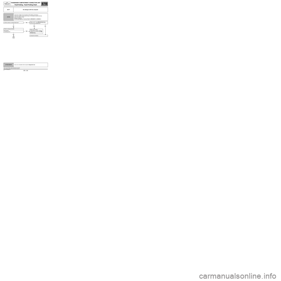
ALP1 No dialogue with the computer
NOTESCheck the condition and connection of the battery connections.
Check the condition of the power fuses on the battery's positive terminal.
Check the battery voltage.
Repair if necessary.
Use Wiring Diagrams Technical Note for MEGANE II or SCENIC II.
Is there contact or another feed level?
NO
Perform locking/unlocking.
Did locking/
unlocking work?
NO
YESRefer to ALP 1 (see 88B, Multiplexing).
Has the fault disappeared?
YES NO
YESRefer to the section
Interpretation of faults, Multiplex
network out of service (see 88B
Multiplexing).
Contact the Techline.
AFTER REPAIRCarry out a complete check using the diagnostic tool.
UCH_V44_ALP1/UCH_V48_ALP1/ UCH_V4C_ALP1/
UCH_V4D_ALP1 /UCH_V4F_ALP1/UCH_V50_ALP1
MR-372-J84-87B000$903.mif
Page 306 of 391
PASSENGER COMPARTMENT CONNECTION UNIT
Fault finding - Fault Finding Chart87B
87B - 306
PASSENGER COMPARTMENT CONNECTION UNIT
Fault finding - Fault Finding Chart87B
87B - 306V9 MR-372-J84-87B000$903.mif
UCH
Vdiag No.: 44, 48,
4C, 4D, 4F, 50
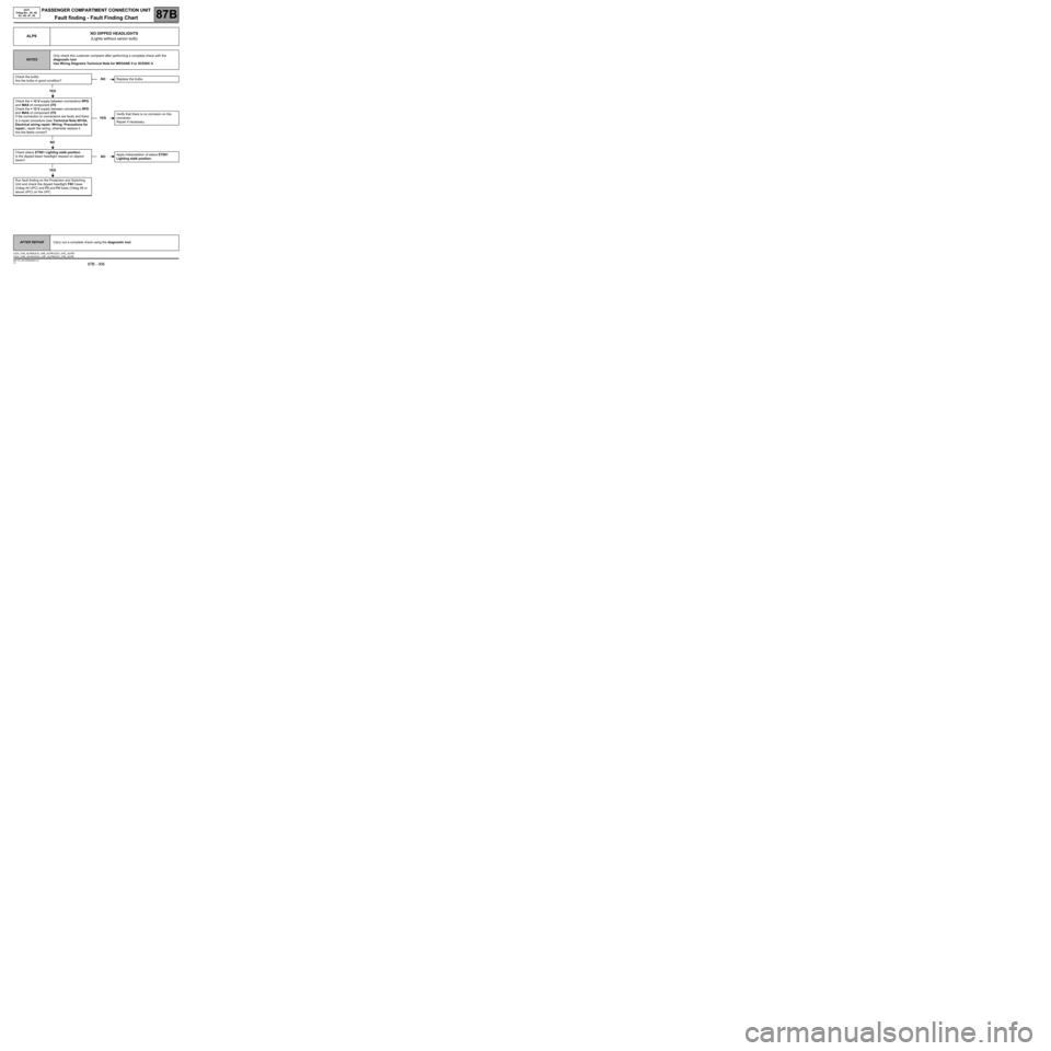
ALP6NO DIPPED HEADLIGHTS
(Lights without xenon bulb)
NOTESOnly check this customer complaint after performing a complete check with the
diagnostic tool.
Use Wiring Diagrams Technical Note for MEGANE II or SCENIC II.
Check the bulbs.
Are the bulbs in good condition?
YES
Check the + 12 V supply between connections RPG
and MAS of component 270.
Check the + 12 V supply between connections RPD
and MAS of component 270.
If the connection or connections are faulty and there
is a repair procedure (see Technical Note 6015A,
Electrical wiring repair, Wiring: Precautions for
repair), repair the wiring, otherwise replace it.
Are the feeds correct?
NO
Check status ET081 Lighting stalk position.
Is the dipped beam headlight request on dipped
beam?
YES
Run fault finding on the Protection and Switching
Unit and check the dipped headlight F8C fuses
(Vdiag 44 UPC) and F3 and F4 fuses (Vdiag 48 or
above UPC) on the UPC.
NOReplace the bulbs.
YESVerify that there is no corrosion on the
connector.
Repair if necessary.
NOApply interpretation of status ET081
Lighting stalk position.
AFTER REPAIRCarry out a complete check using the diagnostic tool.
UCH_V44_ALP6/UCH_V48_ALP6/ UCH_V4C_ALP6/
UCH_V4D_ALP6 /UCH_V4F_ALP6/UCH_V50_ALP6