ESP RENAULT SCENIC 2009 J84 / 2.G Automatic Transmission AJ0 BVA User Guide
[x] Cancel search | Manufacturer: RENAULT, Model Year: 2009, Model line: SCENIC, Model: RENAULT SCENIC 2009 J84 / 2.GPages: 162
Page 126 of 162
AUTOMATIC TRANSMISSION
Fault finding - Interpretation of statuses
23A
23A - 126V3 MR-372-J84-23A000$675.mif
AJ0 BVA
Vdiag No.: 04, 05
ET097
MANUAL MODE
Note:
Status ET097 "Manual mode" is applicable for the following sub-functions:
–"Gear changes".
–"Driver parameters".
STATUS
DEFINITIONINACTIVE: indicates that the manual mode is inactive whenever the gear lever is not
in "M" position, or when manual mode is faulty.
M +: shows that the gear lever is in position M +.
M -: shows that the gear lever is in position M -.
ACTIVE: indicates that manual mode is active when the gear lever is in position "M".
NOTESSpecial notes:
Apply the conformity check to see if the statuses are consistent with the operating
programs of the system.
Conformity check with engine stopped, ignition on or engine running.
INACTIVE
Check that, with gear lever in a position other than "M", status ET097 "Manual mode"
is "INACTIVE".
If a fault occurs, check that status ET012 "Gear lever position" corresponds to the lever
position.
Look for any damage to the wiring and check the condition and connection of the
connectors for components 119 and 129.
If the connection is faulty and there is a repair procedure (see Technical Note 6015A,
Electrical wiring repair, Wiring: Precautions for repair), repair the wiring, otherwise
replace it.
Check the continuity and insulation of the following connections:
●connection code 5H (sequential lever M+ signal),
●connection code 5FM (sequential lever M- signal),
between components 119 and 129.
Check for + 12 V after ignition feed on connection AP43 of component 129.
Check for earth on connection N+ of component 129.
If the connection or connections are faulty and there is a repair procedure (see
Technical Note 6015A, Electrical wiring repair, Wiring: Precautions for repair),
repair the wiring, otherwise replace it.
AFTER REPAIRCarry out a road test, then check with the diagnostic tool.
AJ0_V04_ET097/AJ0_V05_ET097
Page 127 of 162
AUTOMATIC TRANSMISSION
Fault finding - Interpretation of statuses
23A
23A - 127V3 MR-372-J84-23A000$675.mif
AJ0 BVA
Vdiag No.: 04, 05
ET097
CONTINUED 1
M+
M-
Check that, with gear lever in position "M +", status ET097 "Manual mode" is "M +".
In the event of a fault, check that lever position "M" in Manual mode matches status
ET012 "Gear lever position".
Check, by moving the gear lever to "M+" and "M-", that the two positions correspond to
the two statuses "M+" and "M-" of status ET097 "Manual mode".
Look for any damage to the wiring and check the condition and connection of the
connectors for components 119 and 129.
If the connection is faulty and there is a repair procedure (see Technical Note 6015A,
Electrical wiring repair, Wiring: Precautions for repair), repair the wiring, otherwise
replace it.
Check the continuity and insulation of the following connections:
●connection code 5H (sequential lever M+ signal),
between components 119 and 129.
Check for + 12 V after ignition feed on connection AP43 of component 129.
Check for earth on connection N+ of component 129.
If the connection or connections are faulty and there is a repair procedure
(see Technical Note 6015A, Electrical wiring repair, Wiring: Precautions for repair),
repair the wiring, otherwise replace it.
Check that, with gear lever in position "M -", status ET097 "Manual mode" is "M -".
In the event of a fault, check that status ET012 "Gear lever position" corresponds to
the lever position in Manual mode "M".
Check, by moving the gear lever to "M+" and "M-", that the two positions correspond to
the two statuses "M+" and "M-" of status ET097 "Manual mode".
Look for any damage to the wiring and check the condition and connection of the
connectors for components 119 and 129.
If the connection is faulty and there is a repair procedure (see Technical Note 6015A,
Electrical wiring repair, Wiring: Precautions for repair), repair the wiring, otherwise
replace it.
Check the continuity and insulation of the following connections:
●connection code 5FM (sequential lever "M-" control),
between components 119 and 129.
Check for + 12 V after ignition feed on connection AP43 of component 129.
Check for earth on connection N+ of component 129.
If the connection or connections are faulty and there is a repair procedure
(see Technical Note 6015A, Electrical wiring repair, Wiring: Precautions for repair),
repair the wiring, otherwise replace it.
AFTER REPAIRCarry out a road test, then check with the diagnostic tool.
Page 128 of 162
AUTOMATIC TRANSMISSION
Fault finding - Interpretation of statuses
23A
23A - 128V3 MR-372-J84-23A000$675.mif
AJ0 BVA
Vdiag No.: 04, 05
ET097
CONTINUED 2
ACTIVE
Check that, with gear lever in position "M", status ET097 "Manual mode" is "ACTIVE".
In the event of a fault, check that status ET012 "Gear lever position" corresponds to
the lever position in Manual mode "M".
Check, by moving the gear lever to "M+" and "M-", that the two positions correspond to
the two statuses "M+" and "M-" of status ET097 "Manual mode".
Look for any damage to the wiring and check the condition and connection of the
connectors for components 119 and 129.
If the connection is faulty and there is a repair procedure (see Technical Note 6015A,
Electrical wiring repair, Wiring: Precautions for repair), repair the wiring, otherwise
replace it.
Check the continuity and insulation of the following connections:
●connection code 5H (sequential lever M+ signal),
●connection code 5FM (sequential lever M- signal),
between components 119 and 129.
Check for + 12 V after ignition feed on connection AP43 of component 129.
Check for earth on connection N+ of component 129.
If the connection or connections are faulty and there is a repair procedure
(see Technical Note 6015A, Electrical wiring repair, Wiring: Precautions for repair),
repair the wiring, otherwise replace it.
AFTER REPAIRCarry out a road test, then check with the diagnostic tool.
Page 135 of 162
AUTOMATIC TRANSMISSION
Fault finding - Interpretation of parameters
23A
23A - 135V3 MR-372-J84-23A000$765.mif
AJ0 BVA
Vdiag No.: 04, 05AUTOMATIC TRANSMISSION
Fault finding - Interpretation of parameters
PR004
TRANSMISSION OIL TEMPERATURE
PARAMETER
DEFINITIONThis parameter shows the gearbox oil temperature in ˚C.
NOTESSpecial notes:
Only perform these tests if the parameters do not correspond with the system operation
programming.
No faults should be present or stored.
Conformity check with engine running, engine coolant temperature > 80 ˚C
With the engine running at idle speed, the gearbox oil temperature varies in accordance with the engine coolant
temperature.
- 40 ˚C > PR004 > 150 ˚C
In the event of a fault, consult the interpretation of fault DF023 Gearbox oil temperature sensor.
Sensor electrical conformity
Disconnect the connector of component 119, measure the resistance of the oil temperature sensor
(on the connector of component 119) between the following connections:
●Connection code 5BZ,
●Connection code 5BY.
The resistance should be between:
- 4.208 ± 0.42 kΩΩ Ω Ω
at 20 ˚C,
- 1.947 ± 0.19 kΩΩ Ω Ω
at 40 ˚C,
- 0.988 ± 0.09 kΩΩ Ω Ω
at 60 ˚C.
In the event of a fault, consult the interpretation of fault DF023 Gearbox oil temperature sensor.
AFTER REPAIRCarry out a road test, then check with the diagnostic tool.
AJ0_V04_PR004/AJ0_V05_PR004
MR-372-J84-23A000$765.mif
Page 136 of 162
AUTOMATIC TRANSMISSION
Fault finding - Interpretation of parameters
23A
23A - 136V3 MR-372-J84-23A000$765.mif
AJ0 BVA
Vdiag No.: 04, 05
PR006
ENGINE SPEED
Note:
Parameter PR006 "Engine speed" applies to the following sub-functions:
"Gear changes".
"Torque activation".
"Driver parameters".
PARAMETER
DEFINITIONThis parameter shows the engine speed in rpm.
NOTESSpecial notes:
Only perform these tests if the parameters do not correspond with the system operation
programming.
No faults should be present or stored.
Conformity check with engine stopped and ignition on
PR006 = 0 rpm
In the event of a fault, run a multiplex network test (see 88B, Multiplexing), check the interpretation of the fault
(see 13B EDC16 CP33 M9R 721, Interpretation of faults, DF195 "Camshaft sensor/engine speed
consistency").
Conformity check with engine at idle speed, engine coolant temperature > 80 ˚C
PR006 ≈≈ ≈ ≈
800 rpm
In the event of a fault, check the interpretation of fault (see 13B EDC16 CP33 M9R 721, Interpretation of faults,
DF195 "Camshaft sensor/engine speed consistency").
AFTER REPAIRCarry out a road test, then check with the diagnostic tool.
AJ0_V04_PR006/AJ0_V05_PR006
Page 137 of 162
AUTOMATIC TRANSMISSION
Fault finding - Interpretation of parameters
23A
23A - 137V3 MR-372-J84-23A000$765.mif
AJ0 BVA
Vdiag No.: 04, 05
PR007
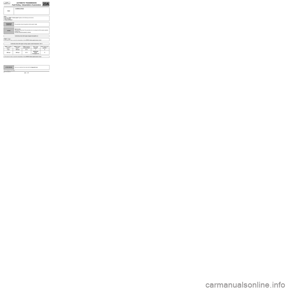
TURBINE SPEED
Note:
Parameter PR007 "Turbine speed" applies to the following sub-functions:
"Gear changes".
"Torque activation".
PARAMETER
DEFINITIONThis parameter shows the gearbox turbine speed in rpm.
NOTESSpecial notes:
Only perform these tests if the parameters do not correspond with the system operation
programming.
No faults should be present or stored.
Conformity check with engine stopped and ignition on
PR007 = 0 rpm
In the event of a fault, consult the interpretation of fault DF038 Turbine speed sensor circuit.
Conformity check with engine running, engine coolant temperature > 80 ˚C
PR007 "Turbine
speed"PR006 "Engine
speed"PR004 "Gearbox
oil temperature"ET013 "Gear
engaged"ET012 "Gear lever
position"
0 rpm≈ 800 rpm 25 ˚C 1 D
≈ 660 rpm≈ 800 rpm 25 ˚CDISENGAGE
(clutch
disengagement)D
In the event of a fault, consult the interpretation of fault DF038 Turbine speed sensor circuit.
AFTER REPAIRCarry out a road test, then check with the diagnostic tool.
AJ0_V04_PR007/AJ0_V05_PR007
Page 138 of 162
AUTOMATIC TRANSMISSION
Fault finding - Interpretation of parameters
23A
23A - 138V3 MR-372-J84-23A000$765.mif
AJ0 BVA
Vdiag No.: 04, 05
PR008
COMPUTER SUPPLY VOLTAGE
PARAMETER
DEFINITIONThis parameter shows the computer feed voltage in volts.
NOTESSpecial notes:
Only perform these tests if the parameters do not correspond with the system operation
programming.
No faults should be present or stored.
Conformity check with engine stopped and ignition on, engine running, engine coolant
temperature > 80 ˚C
Look for any damage to the wiring and check the condition and connection of the connectors for components 119
and 1337.
If the connection is faulty and there is a repair procedure (see Technical Note 6015A, Electrical wiring repair,
Wiring: Precautions for repair), repair the wiring, otherwise replace it.
Check the continuity and insulation of the following connections:
●Connection code BP42,
between components 119 and 1337.
●Connection code AP4,
between components 119 and 1337.
Check for + 12 V after ignition feed on connection BP42 of component 119.
Check for + 12 V after ignition feed on connection AP4 of component 119.
If the connection or connections are faulty and there is a repair procedure (see Technical Note 6015A, Electrical
wiring repair, Wiring: Precautions for repair), repair the wiring, otherwise replace it.
Check for earth on connection N of component 119.
If the connection or connections are faulty and there is a repair procedure (see Technical Note 6015A, Electrical
wiring repair, Wiring: Precautions for repair), repair the wiring, otherwise replace it.
If the fault is still present, contact Techline.
AFTER REPAIRCarry out a road test, then check with the diagnostic tool.
AJ0_V04_PR008/AJ0_V05_PR008
Page 139 of 162
AUTOMATIC TRANSMISSION
Fault finding - Interpretation of parameters
23A
23A - 139V3 MR-372-J84-23A000$765.mif
AJ0 BVA
Vdiag No.: 04, 05
PR022
ACCELERATOR PEDAL POSITION
Note:
Parameter PR022 "Accelerator pedal position" applies to the following sub-functions:
"Gear changes".
"Torque activation".
"Driver parameters".
PARAMETER
DEFINITIONThis parameter indicates the accelerator pedal position as a %.
NOTESSpecial notes:
Only perform these tests if the parameters do not correspond with the system operation
programming.
No faults should be present or stored.
Conformity check with engine stopped and ignition on
Full load: PR022 "Accelerator pedal position" ≈≈ ≈ ≈
114 % and PR067 "Calculated accelerator pedal position"
= 100 %.
In the event of a fault (see 13B EDC16 CP33 M9R 721, Interpretation of faults, DF196 "Pedal sensor gang 1
circuit" or DF198 "Pedal sensor gang 2 circuit").
AFTER REPAIRCarry out a road test, then check with the diagnostic tool.
AJ0_V04_PR022/AJ0_V05_PR022
Page 140 of 162
AUTOMATIC TRANSMISSION
Fault finding - Interpretation of parameters
23A
23A - 140V3 MR-372-J84-23A000$765.mif
AJ0 BVA
Vdiag No.: 04, 05
PR067
CALCULATED ACCELERATOR PEDAL POSITION
Note:
Parameter PR067 "Accelerator pedal position" applies to the following sub-functions:
"Gear changes".
"Torque activation".
PARAMETER
DEFINITIONThis signal is supplied by the injection computer when the cruise control/speed limiter
is operating and when there is no longer a signal from the accelerator pedal. This
parameter indicates the accelerator pedal position as a %.
NOTESSpecial notes:
Only perform these tests if the parameters do not correspond with the system operation
programming.
No faults should be present or stored.
Conformity check with engine stopped and ignition on, engine running, engine coolant
temperature > 80 ˚C
Full load: PR022 "Accelerator pedal position" ≈≈ ≈ ≈
114 % and PR067 "Calculated accelerator pedal position"
= 100 %.
In the event of a fault (see 13B EDC16 CP33 M9R 721, Interpretation of faults, DF196 "Pedal sensor gang 1
circuit" or DF198 "Pedal sensor gang 2 circuit").
AFTER REPAIRCarry out a road test, then check with the diagnostic tool.
AJ0_V04_PR067/AJ0_V05_PR067
Page 141 of 162
AUTOMATIC TRANSMISSION
Fault finding - Interpretation of parameters
23A
23A - 141V3 MR-372-J84-23A000$765.mif
AJ0 BVA
Vdiag No.: 04, 05
PR105
VEHICLE SPEED
Note:
Parameter PR105 "Vehicle speed" applies to the following sub-functions:
"Gear changes".
"Driver parameters".
PARAMETER
DEFINITIONThis parameter indicates the vehicle speed in mph (km/h).
NOTESSpecial notes:
Only perform these tests if the parameters do not correspond with the system operation
programming.
No faults should be present or stored.
Conformity check with engine stopped and ignition on
0 mph (km/h)
In the event of a fault, consult the interpretation of fault DF171 Vehicle speed sensor circuit.
Conformity check with engine running, engine coolant temperature > 80 ˚C
In the event of a fault, consult the interpretation of fault DF171 Vehicle speed sensor circuit.
AFTER REPAIRCarry out a road test, then check with the diagnostic tool.
AJ0_V04_PR105/AJ0_V05_PR105