check engine RENAULT SCENIC 2011 J95 / 3.G Engine And Peripherals EDC16 Injection Workshop Manual
[x] Cancel search | Manufacturer: RENAULT, Model Year: 2011, Model line: SCENIC, Model: RENAULT SCENIC 2011 J95 / 3.GPages: 236, PDF Size: 1.32 MB
Page 166 of 236

DIESEL INJECTION
Fault finding - Interpretation of statuses13B
13B-166V10 MR-372-J84-13B150$564.mif
EDC16 INJECTION
Program No.: C1
Vdiag No.: 44, 48 and 4C
ET238
SYNCHRONISATION
NOTESOnly perform the tests if the statuses do not correspond with the system programming
functions.
WARNING
Synchronisation is carried out during the engine starting phase. This is established between the camshaft
position sensor and the TDC sensor.
Once this synchronisation has been carried out, it enables the computer to identify cylinder no.1 and to
ascertain the precise position of the cylinder's top dead centre.
INACTIVE
COMPLETED
When the engine is stopped but the ignition switched on, cylinder no. 1 is no longer
indicated.
Status ET238 is INACTIVE, no synchronisation between the crankshaft and the
camshaft is performed.
Synchronisation is carried out during the engine starting phase.
Cylinder No. 1 is indicated and synchronisation will be performed once the engine is
started.
Status ET238 is "COMPLETED".
If after several attempts to start the engine status ET238 remains INACTIVE, refer to the
interpretation of the following faults:
–DF005 Engine speed sensor circuit
–DF097 Camshaft sensor circuit
If the engine still does not start, (see Customer complaints, ALP2 Starting faults).
AFTER REPAIRCarry out a road test followed by another check with the diagnostic tool.
EDC16_V44_ET238/EDC16_V48_ET238/EDC16_V4C_ET238
Page 167 of 236
13B-167
DIESEL INJECTION
Fault finding - Interpretation of statuses13B
V10 MR-372-J84-13B150$564.mif
EDC16 INJECTION
Program No.: C1
Vdiag No.: 44, 48 and 4C
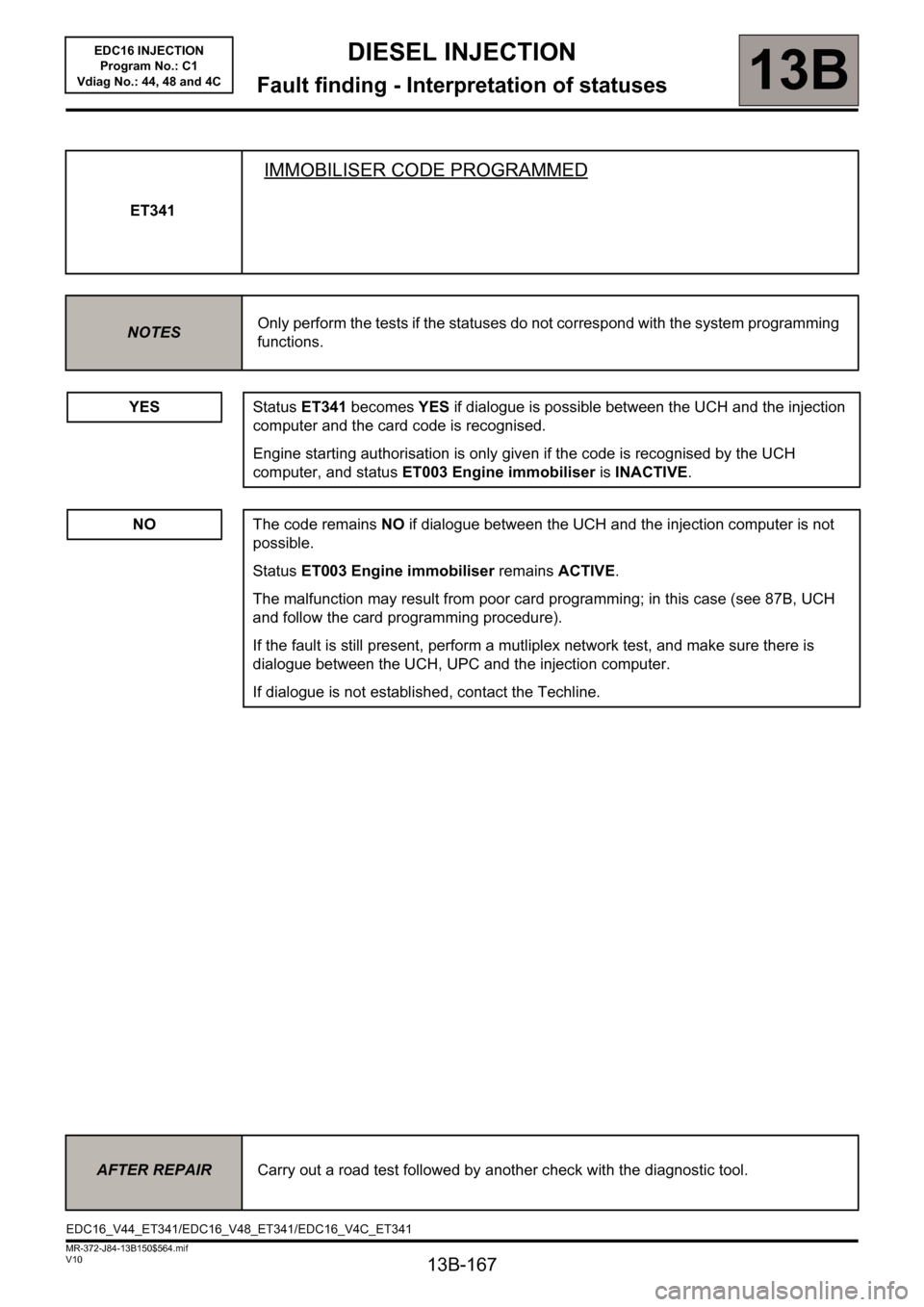
ET341
IMMOBILISER CODE PROGRAMMED
NOTESOnly perform the tests if the statuses do not correspond with the system programming
functions.
YESStatus ET341 becomes YES if dialogue is possible between the UCH and the injection
computer and the card code is recognised.
Engine starting authorisation is only given if the code is recognised by the UCH
computer, and status ET003 Engine immobiliser is INACTIVE.
NOThe code remains NO if dialogue between the UCH and the injection computer is not
possible.
Status ET003 Engine immobiliser remains ACTIVE.
The malfunction may result from poor card programming; in this case (see 87B, UCH
and follow the card programming procedure).
If the fault is still present, perform a mutliplex network test, and make sure there is
dialogue between the UCH, UPC and the injection computer.
If dialogue is not established, contact the Techline.
AFTER REPAIRCarry out a road test followed by another check with the diagnostic tool.
EDC16_V44_ET341/EDC16_V48_ET341/EDC16_V4C_ET341
Page 168 of 236
13B-168
DIESEL INJECTION
Fault finding - Interpretation of statuses13B
V10 MR-372-J84-13B150$564.mif
EDC16 INJECTION
Program No.: C1
Vdiag No.: 44, 48 and 4C
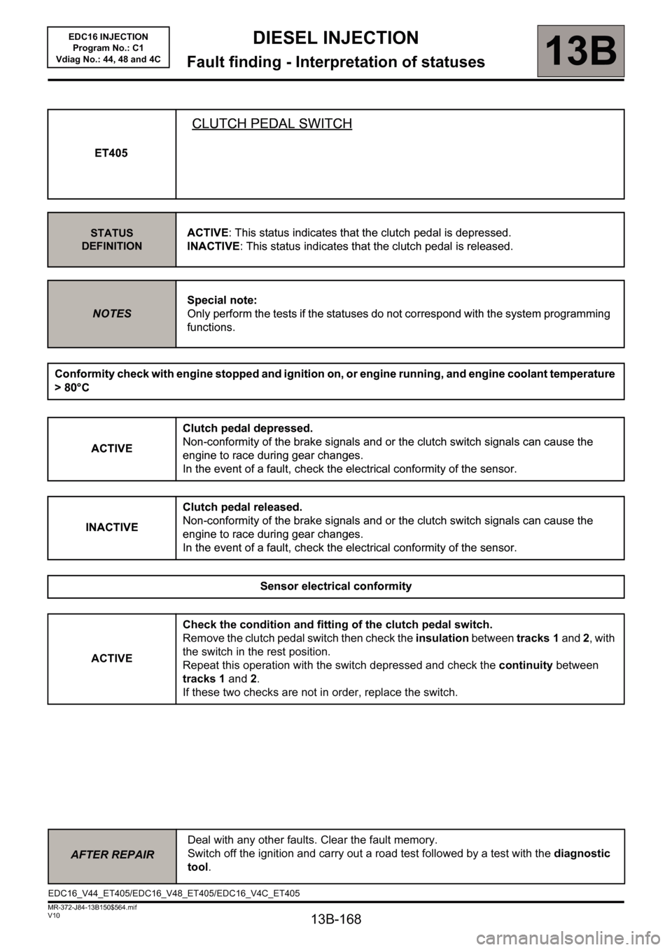
ET405
CLUTCH PEDAL SWITCH
STATUS
DEFINITIONACTIVE: This status indicates that the clutch pedal is depressed.
INACTIVE: This status indicates that the clutch pedal is released.
NOTESSpecial note:
Only perform the tests if the statuses do not correspond with the system programming
functions.
Conformity check with engine stopped and ignition on, or engine running, and engine coolant temperature
> 80°C
ACTIVEClutch pedal depressed.
Non-conformity of the brake signals and or the clutch switch signals can cause the
engine to race during gear changes.
In the event of a fault, check the electrical conformity of the sensor.
INACTIVEClutch pedal released.
Non-conformity of the brake signals and or the clutch switch signals can cause the
engine to race during gear changes.
In the event of a fault, check the electrical conformity of the sensor.
Sensor electrical conformity
ACTIVECheck the condition and fitting of the clutch pedal switch.
Remove the clutch pedal switch then check the insulation between tracks 1 and 2, with
the switch in the rest position.
Repeat this operation with the switch depressed and check the continuity between
tracks 1 and 2.
If these two checks are not in order, replace the switch.
AFTER REPAIRDeal with any other faults. Clear the fault memory.
Switch off the ignition and carry out a road test followed by a test with the diagnostic
tool.
ET405
CLUTCH PEDAL SWITCH
STATUS
DEFINITIONACTIVE: This status indicates that the clutch pedal is depressed.
INACTIVE: This status indicates that the clutch pedal is released.
NOTESSpecial note:
Only perform the tests if the statuses do not correspond with the system programming
functions.
Conformity check with engine stopped and ignition on, or engine running, and engine coolant temperature
> 80°C
ACTIVEClutch pedal depressed.
Non-conformity of the brake signals and or the clutch switch signals can cause the
engine to race during gear changes.
In the event of a fault, check the electrical conformity of the sensor.
INACTIVEClutch pedal released.
Non-conformity of the brake signals and or the clutch switch signals can cause the
engine to race during gear changes.
In the event of a fault, check the electrical conformity of the sensor.
Sensor electrical conformity
EDC16_V44_ET405/EDC16_V48_ET405/EDC16_V4C_ET405
Page 171 of 236
13B-171
DIESEL INJECTION
Fault finding - Interpretation of statuses13B
V10 MR-372-J84-13B150$564.mif
EDC16 INJECTION
Program No.: C1
Vdiag No.: 44, 48 and 4C
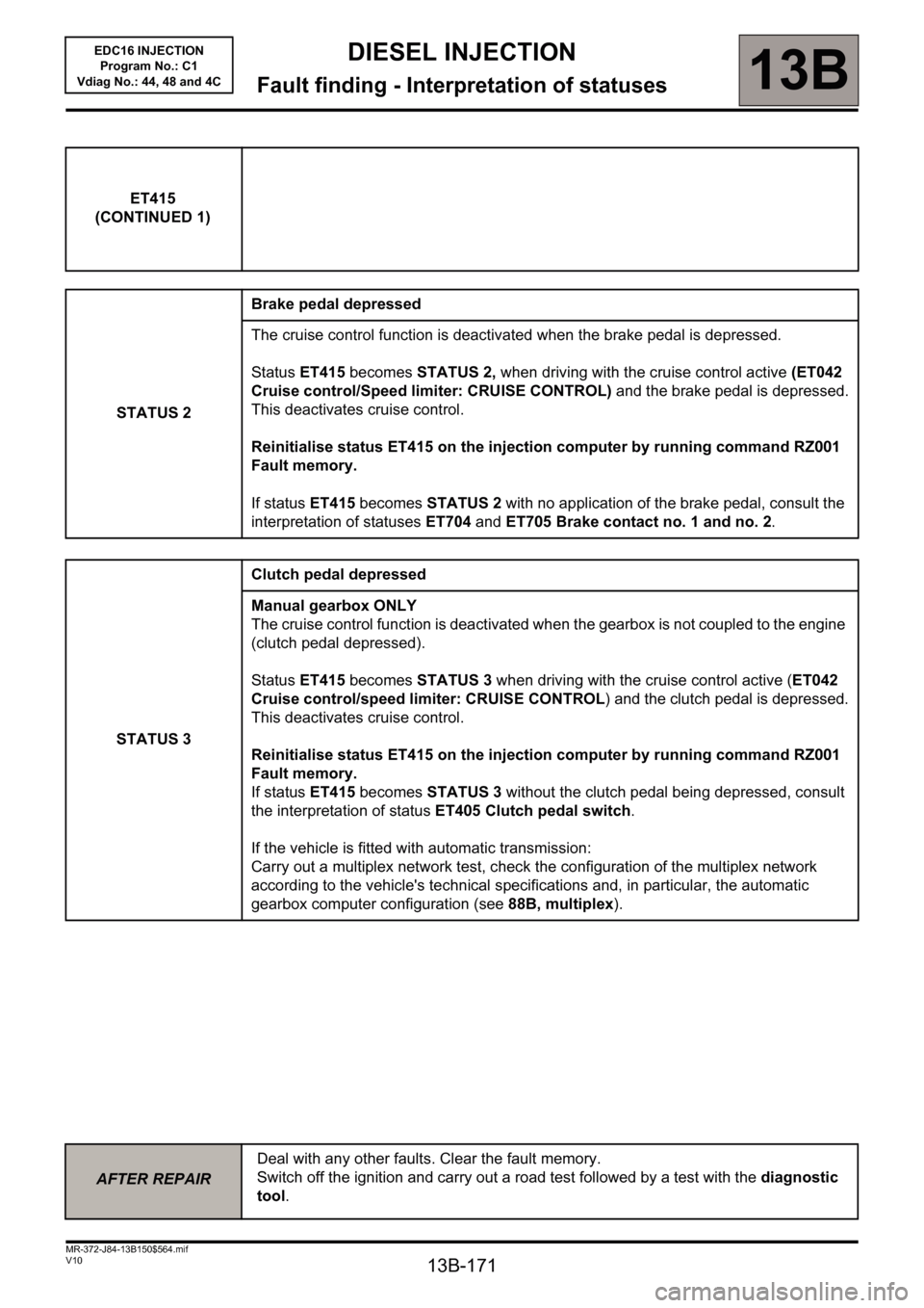
ET415
(CONTINUED 1)
STATUS 2Brake pedal depressed
The cruise control function is deactivated when the brake pedal is depressed.
Status ET415 becomes STATUS 2, when driving with the cruise control active (ET042
Cruise control/Speed limiter: CRUISE CONTROL) and the brake pedal is depressed.
This deactivates cruise control.
Reinitialise status ET415 on the injection computer by running command RZ001
Fault memory.
If status ET415 becomes STATUS 2 with no application of the brake pedal, consult the
interpretation of statuses ET704 and ET705 Brake contact no. 1 and no. 2.
STATUS 3Clutch pedal depressed
Manual gearbox ONLY
The cruise control function is deactivated when the gearbox is not coupled to the engine
(clutch pedal depressed).
Status ET415 becomes STATUS 3 when driving with the cruise control active (ET042
Cruise control/speed limiter: CRUISE CONTROL) and the clutch pedal is depressed.
This deactivates cruise control.
Reinitialise status ET415 on the injection computer by running command RZ001
Fault memory.
If status ET415 becomes STATUS 3 without the clutch pedal being depressed, consult
the interpretation of status ET405 Clutch pedal switch.
If the vehicle is fitted with automatic transmission:
Carry out a multiplex network test, check the configuration of the multiplex network
according to the vehicle's technical specifications and, in particular, the automatic
gearbox computer configuration (see 88B, multiplex).
AFTER REPAIRDeal with any other faults. Clear the fault memory.
Switch off the ignition and carry out a road test followed by a test with the diagnostic
tool.
Page 183 of 236
13B - 183
DIESEL INJECTION
Fault finding - Interpretation of parameters13B
V10 MR-372-J84-13B150$658.mif
EDC16 INJECTION
Program No.: C1
Vdiag No: 44, 48 and 4C
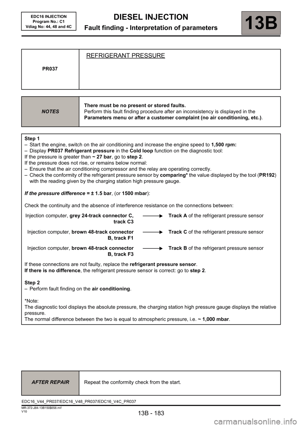
PR037
REFRIGERANT PRESSURE
NOTESThere must be no present or stored faults.
Perform this fault finding procedure after an inconsistency is displayed in the
Parameters menu or after a customer complaint (no air conditioning, etc.).
Step 1
– Start the engine, switch on the air conditioning and increase the engine speed to 1,500 rpm:
– Display PR037 Refrigerant pressure in the Cold loop function on the diagnostic tool:
If the pressure is greater than ~27bar, go to step 2.
If the pressure does not rise, or remains below normal:
– Ensure that the air conditioning compressor and the relay are operating correctly.
– Check the conformity of the refrigerant pressure sensor by comparing* the value displayed by the tool (PR192)
with the reading given by the charging station high pressure gauge.
If the pressure difference = ±1.5bar, (or 1500 mbar):
Check the continuity and the absence of interference resistance on the connections between:
Injection computer, grey 24-track connector C,
track C3Track A of the refrigerant pressure sensor
Injection computer, brown 48-track connector
B, track F1Track C of the refrigerant pressure sensor
Injection computer, brown 48-track connector
B, track F3Track B of the refrigerant pressure sensor
If these connections are not faulty, replace the refrigerant pressure sensor.
If there is no difference, the refrigerant pressure sensor is correct: go to step 2.
Step 2
– Perform fault finding on the air conditioning.
*Note:
The diagnostic tool displays the absolute pressure, the charging station high pressure gauge displays the relative
pressure.
The normal difference between the two is equal to atmospheric pressure, i.e. ~1,000mbar.
AFTER REPAIRRepeat the conformity check from the start.
EDC16_V44_PR037/EDC16_V48_PR037/EDC16_V4C_PR037
Page 186 of 236
13B - 186
DIESEL INJECTION
Fault finding - Interpretation of parameters13B
V10 MR-372-J84-13B150$658.mif
EDC16 INJECTION
Program No.: C1
Vdiag No: 44, 48 and 4C
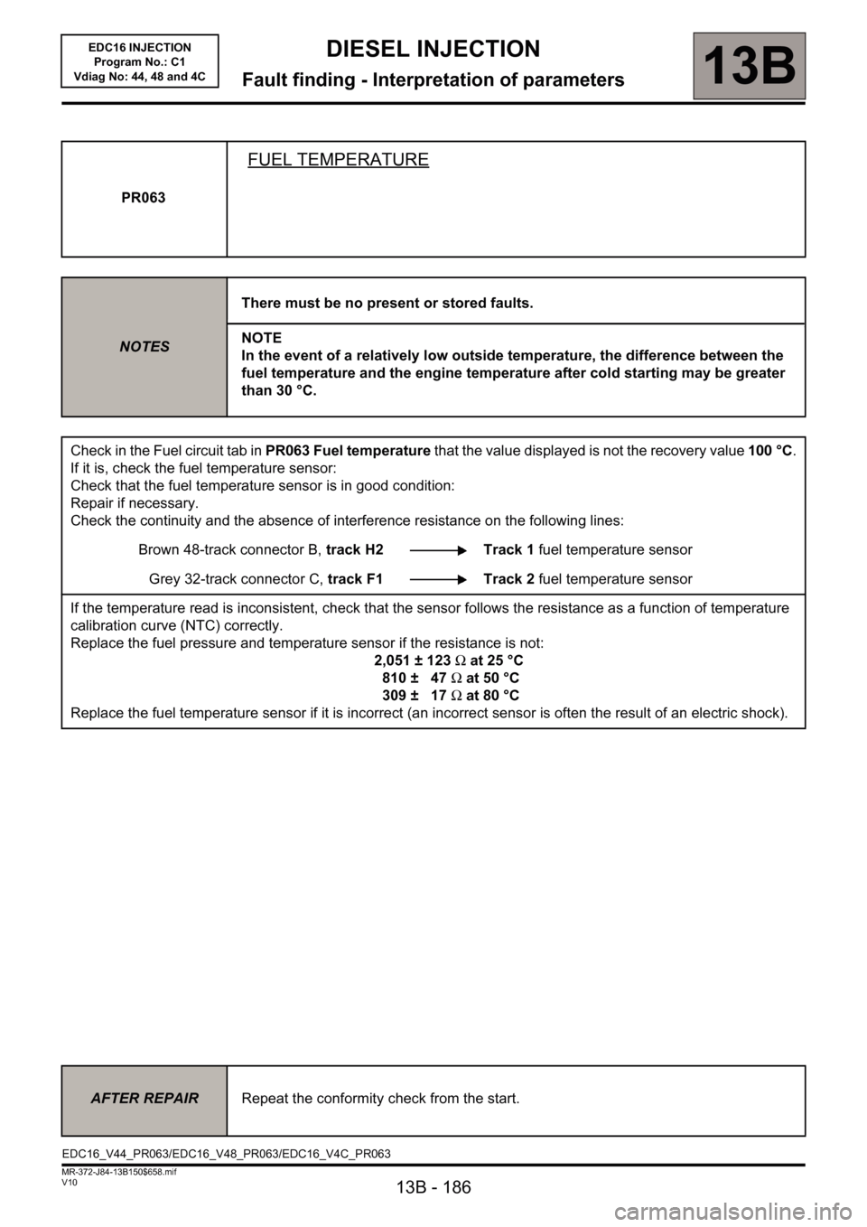
PR063
FUEL TEMPERATURE
NOTESThere must be no present or stored faults.
NOTE
In the event of a relatively low outside temperature, the difference between the
fuel temperature and the engine temperature after cold starting may be greater
than 30 °C.
Check in the Fuel circuit tab in PR063 Fuel temperature that the value displayed is not the recovery value 100 °C.
If it is, check the fuel temperature sensor:
Check that the fuel temperature sensor is in good condition:
Repair if necessary.
Check the continuity and the absence of interference resistance on the following lines:
Brown 48-track connector B, track H2 Track 1 fuel temperature sensor
Grey 32-track connector C, track F1 Track 2 fuel temperature sensor
If the temperature read is inconsistent, check that the sensor follows the resistance as a function of temperature
calibration curve (NTC) correctly.
Replace the fuel pressure and temperature sensor if the resistance is not:
2,051 ± 123Ω at 25 °C
810 ± 47Ω at 50 °C
309 ± 17Ω at 80 °C
Replace the fuel temperature sensor if it is incorrect (an incorrect sensor is often the result of an electric shock).
AFTER REPAIRRepeat the conformity check from the start.
EDC16_V44_PR063/EDC16_V48_PR063/EDC16_V4C_PR063
Page 189 of 236
13B - 189
DIESEL INJECTION
13B
V10 MR-372-J84-13B150$752.mif
EDC16 INJECTION
Program No.: C1
Vdiag No: 44, 48 and 4CDIESEL INJECTION
Fault finding - Interpretation of commands
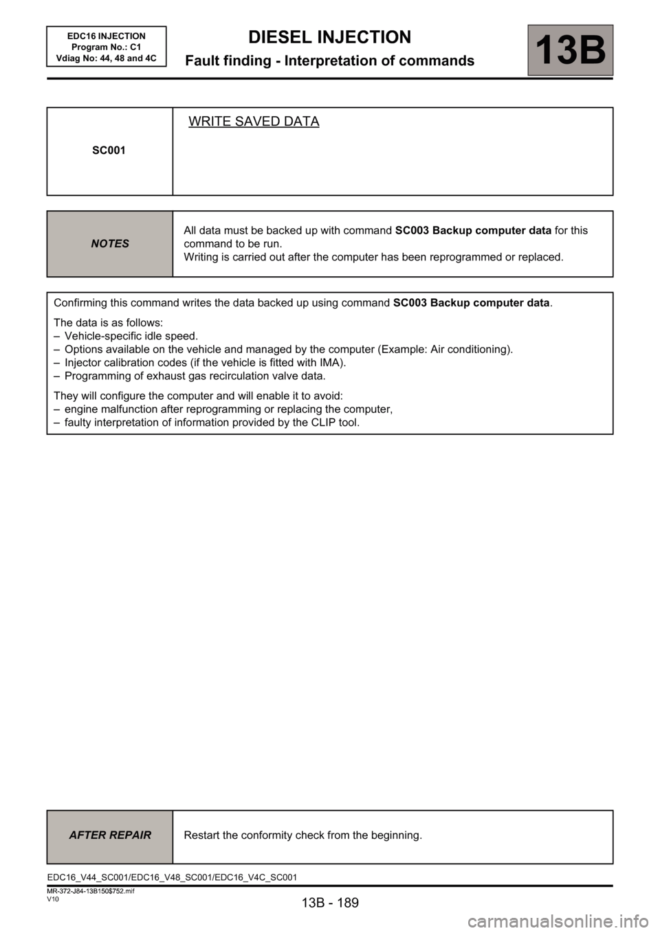
SC001
WRITE SAVED DATA
NOTESAll data must be backed up with command SC003 Backup computer data for this
command to be run.
Writing is carried out after the computer has been reprogrammed or replaced.
Confirming this command writes the data backed up using command SC003 Backup computer data.
The data is as follows:
– Vehicle-specific idle speed.
– Options available on the vehicle and managed by the computer (Example: Air conditioning).
– Injector calibration codes (if the vehicle is fitted with IMA).
– Programming of exhaust gas recirculation valve data.
They will configure the computer and will enable it to avoid:
– engine malfunction after reprogramming or replacing the computer,
– faulty interpretation of information provided by the CLIP tool.
AFTER REPAIRRestart the conformity check from the beginning.
EDC16_V44_SC001/EDC16_V48_SC001/EDC16_V4C_SC001
MR-372-J84-13B150$752.mif
Page 190 of 236
13B - 190
DIESEL INJECTION
Fault finding - Interpretation of commands13B
V10 MR-372-J84-13B150$752.mif
EDC16 INJECTION
Program No.: C1
Vdiag No: 44, 48 and 4C
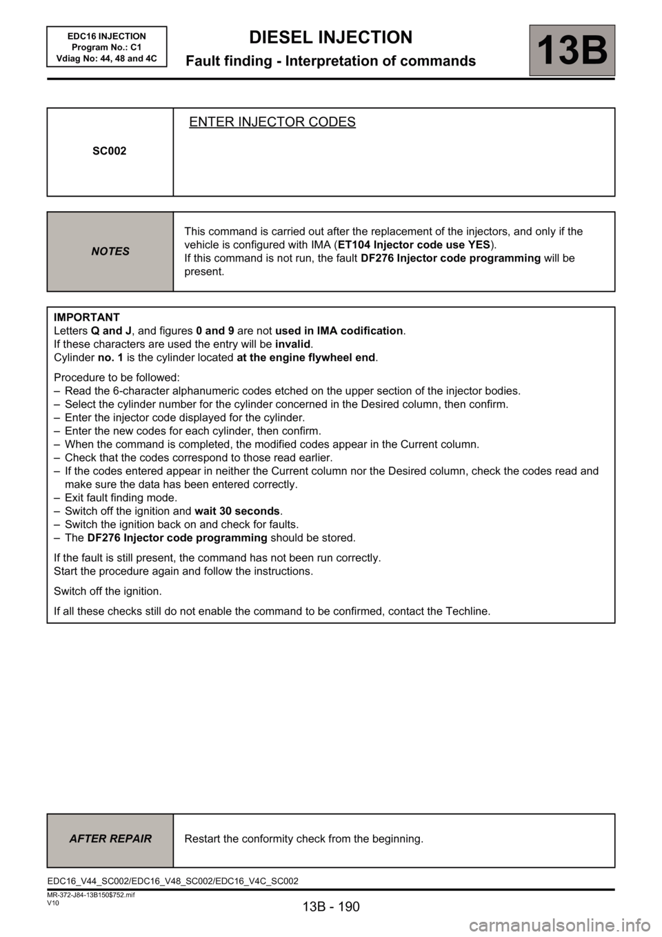
SC002
ENTER INJECTOR CODES
NOTESThis command is carried out after the replacement of the injectors, and only if the
vehicle is configured with IMA (ET104 Injector code use YES).
If this command is not run, the fault DF276 Injector code programming will be
present.
IMPORTANT
Letters Q and J, and figures 0 and 9 are not used in IMA codification.
If these characters are used the entry will be invalid.
Cylinder no. 1 is the cylinder located at the engine flywheel end.
Procedure to be followed:
– Read the 6-character alphanumeric codes etched on the upper section of the injector bodies.
– Select the cylinder number for the cylinder concerned in the Desired column, then confirm.
– Enter the injector code displayed for the cylinder.
– Enter the new codes for each cylinder, then confirm.
– When the command is completed, the modified codes appear in the Current column.
– Check that the codes correspond to those read earlier.
– If the codes entered appear in neither the Current column nor the Desired column, check the codes read and
make sure the data has been entered correctly.
– Exit fault finding mode.
– Switch off the ignition and wait 30 seconds.
– Switch the ignition back on and check for faults.
–The DF276 Injector code programming should be stored.
If the fault is still present, the command has not been run correctly.
Start the procedure again and follow the instructions.
Switch off the ignition.
If all these checks still do not enable the command to be confirmed, contact the Techline.
AFTER REPAIRRestart the conformity check from the beginning.
EDC16_V44_SC002/EDC16_V48_SC002/EDC16_V4C_SC002
Page 192 of 236
13B - 192
DIESEL INJECTION
Fault finding - Interpretation of commands13B
V10 MR-372-J84-13B150$752.mif
EDC16 INJECTION
Program No.: C1
Vdiag No: 44, 48 and 4C
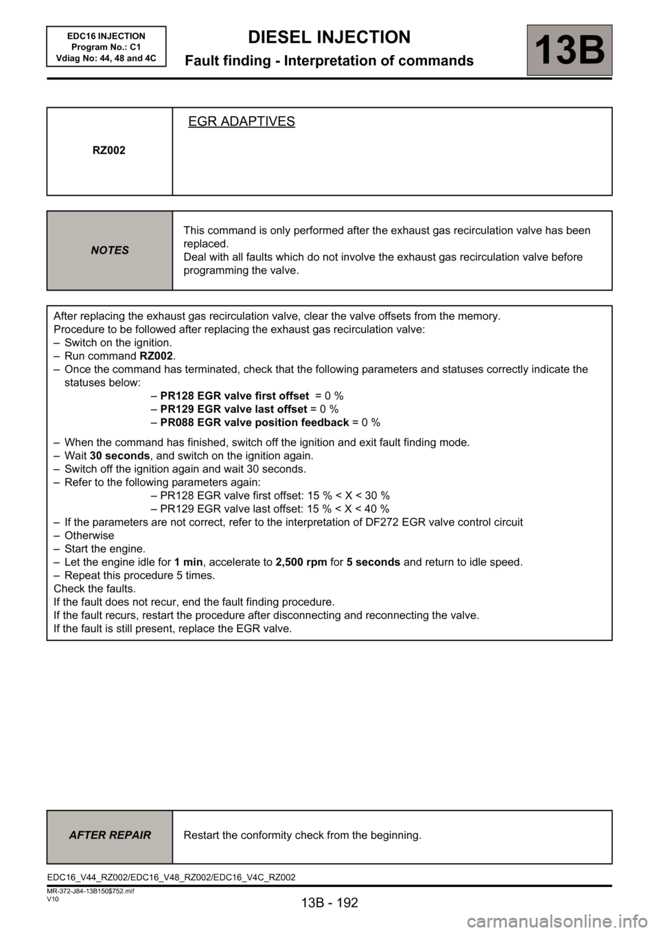
RZ002
EGR ADAPTIVES
NOTESThis command is only performed after the exhaust gas recirculation valve has been
replaced.
Deal with all faults which do not involve the exhaust gas recirculation valve before
programming the valve.
After replacing the exhaust gas recirculation valve, clear the valve offsets from the memory.
Procedure to be followed after replacing the exhaust gas recirculation valve:
– Switch on the ignition.
– Run command RZ002.
– Once the command has terminated, check that the following parameters and statuses correctly indicate the
statuses below:
–PR128 EGR valve first offset = 0 %
–PR129 EGR valve last offset= 0 %
–PR088 EGR valve position feedback= 0 %
– When the command has finished, switch off the ignition and exit fault finding mode.
–Wait 30 seconds, and switch on the ignition again.
– Switch off the ignition again and wait 30 seconds.
– Refer to the following parameters again:
– PR128 EGR valve first offset: 15 % < X < 30 %
– PR129 EGR valve last offset: 15 % < X < 40 %
– If the parameters are not correct, refer to the interpretation of DF272 EGR valve control circuit
–Otherwise
– Start the engine.
– Let the engine idle for 1min, accelerate to 2,500 rpm for 5 seconds and return to idle speed.
– Repeat this procedure 5 times.
Check the faults.
If the fault does not recur, end the fault finding procedure.
If the fault recurs, restart the procedure after disconnecting and reconnecting the valve.
If the fault is still present, replace the EGR valve.
AFTER REPAIRRestart the conformity check from the beginning.
EDC16_V44_RZ002/EDC16_V48_RZ002/EDC16_V4C_RZ002
Page 197 of 236
13B - 197
DIESEL INJECTION
Fault finding - Interpretation of commands13B
V10 MR-372-J84-13B150$752.mif
EDC16 INJECTION
Program No.: C1
Vdiag No: 44, 48 and 4C
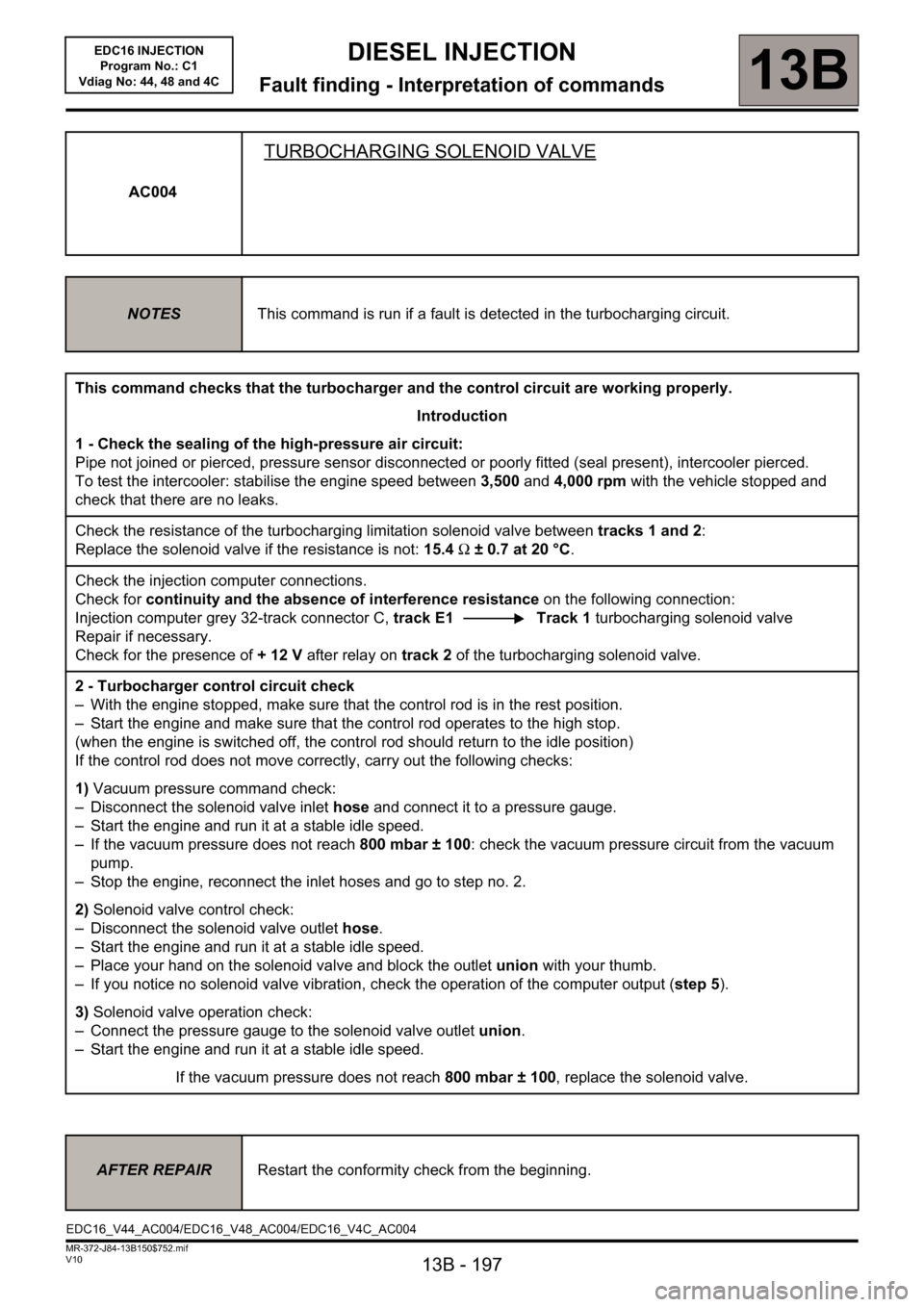
AC004
TURBOCHARGING SOLENOID VALVE
NOTESThis command is run if a fault is detected in the turbocharging circuit.
This command checks that the turbocharger and the control circuit are working properly.
Introduction
1 - Check the sealing of the high-pressure air circuit:
Pipe not joined or pierced, pressure sensor disconnected or poorly fitted (seal present), intercooler pierced.
To test the intercooler: stabilise the engine speed between 3,500 and 4,000 rpm with the vehicle stopped and
check that there are no leaks.
Check the resistance of the turbocharging limitation solenoid valve between tracks 1 and 2:
Replace the solenoid valve if the resistance is not: 15.4 Ω ± 0.7 at 20 °C.
Check the injection computer connections.
Check for continuity and the absence of interference resistance on the following connection:
Injection computer grey 32-track connector C, track E1 Track 1 turbocharging solenoid valve
Repair if necessary.
Check for the presence of +12V after relay on track 2 of the turbocharging solenoid valve.
2 - Turbocharger control circuit check
– With the engine stopped, make sure that the control rod is in the rest position.
– Start the engine and make sure that the control rod operates to the high stop.
(when the engine is switched off, the control rod should return to the idle position)
If the control rod does not move correctly, carry out the following checks:
1) Vacuum pressure command check:
– Disconnect the solenoid valve inlet hose and connect it to a pressure gauge.
– Start the engine and run it at a stable idle speed.
– If the vacuum pressure does not reach 800 mbar ± 100: check the vacuum pressure circuit from the vacuum
pump.
– Stop the engine, reconnect the inlet hoses and go to step no. 2.
2) Solenoid valve control check:
– Disconnect the solenoid valve outlet hose.
– Start the engine and run it at a stable idle speed.
– Place your hand on the solenoid valve and block the outlet union with your thumb.
– If you notice no solenoid valve vibration, check the operation of the computer output (step 5).
3) Solenoid valve operation check:
– Connect the pressure gauge to the solenoid valve outlet union.
– Start the engine and run it at a stable idle speed.
If the vacuum pressure does not reach 800 mbar ± 100, replace the solenoid valve.
AFTER REPAIRRestart the conformity check from the beginning.
EDC16_V44_AC004/EDC16_V48_AC004/EDC16_V4C_AC004