SC036 RENAULT SCENIC 2011 J95 / 3.G Engine And Peripherals EDC16 User Guide
[x] Cancel search | Manufacturer: RENAULT, Model Year: 2011, Model line: SCENIC, Model: RENAULT SCENIC 2011 J95 / 3.GPages: 365, PDF Size: 2.11 MB
Page 119 of 365
13B-119
MR-372-J84-13B200$324.mif
V13
DIESEL INJECTION
Fault finding – Interpretation of faults
EDC16
Program No.: C1
Vdiag no.: 18, 1C, 20,
50, 58, 5C
13B
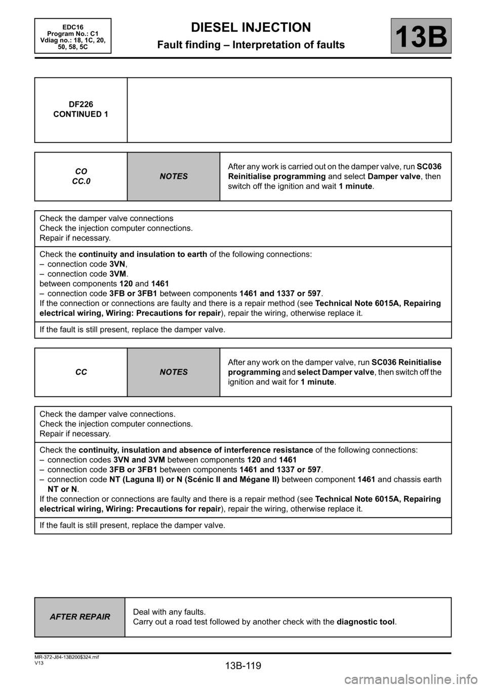
DF226
CONTINUED 1
CO
CC.0
NOTESAfter any work is carried out on the damper valve, run SC036
Reinitialise programming and select Damper valve, then
switch off the ignition and wait 1 minute.
Check the damper valve connections
Check the injection computer connections.
Repair if necessary.
Check the continuity and insulation to earth of the following connections:
– connection code 3VN,
– connection code 3VM.
between components 120 and 1461
– connection code 3FB or 3FB1 between components 1461 and 1337 or 597.
If the connection or connections are faulty and there is a repair method (see Technical Note 6015A, Repairing
electrical wiring, Wiring: Precautions for repair), repair the wiring, otherwise replace it.
If the fault is still present, replace the damper valve.
CC
NOTESAfter any work on the damper valve, run SC036 Reinitialise
programming and select Damper valve, then switch off the
ignition and wait for 1 minute.
Check the damper valve connections.
Check the injection computer connections.
Repair if necessary.
Check the continuity, insulation and absence of interference resistance of the following connections:
– connection codes 3VN and 3VM between components 120 and 1461
– connection code 3FB or 3FB1 between components 1461 and 1337 or 597.
– connection code NT (Laguna II) or N (Scénic II and Mégane II) between component 1461 and chassis earth
NT or N.
If the connection or connections are faulty and there is a repair method (see Technical Note 6015A, Repairing
electrical wiring, Wiring: Precautions for repair), repair the wiring, otherwise replace it.
If the fault is still present, replace the damper valve.
AFTER REPAIRDeal with any faults.
Carry out a road test followed by another check with the diagnostic tool.
Page 120 of 365
13B-120
MR-372-J84-13B200$324.mif
V13
DIESEL INJECTION
Fault finding – Interpretation of faults
EDC16
Program No.: C1
Vdiag no.: 18, 1C, 20,
50, 58, 5C
13B
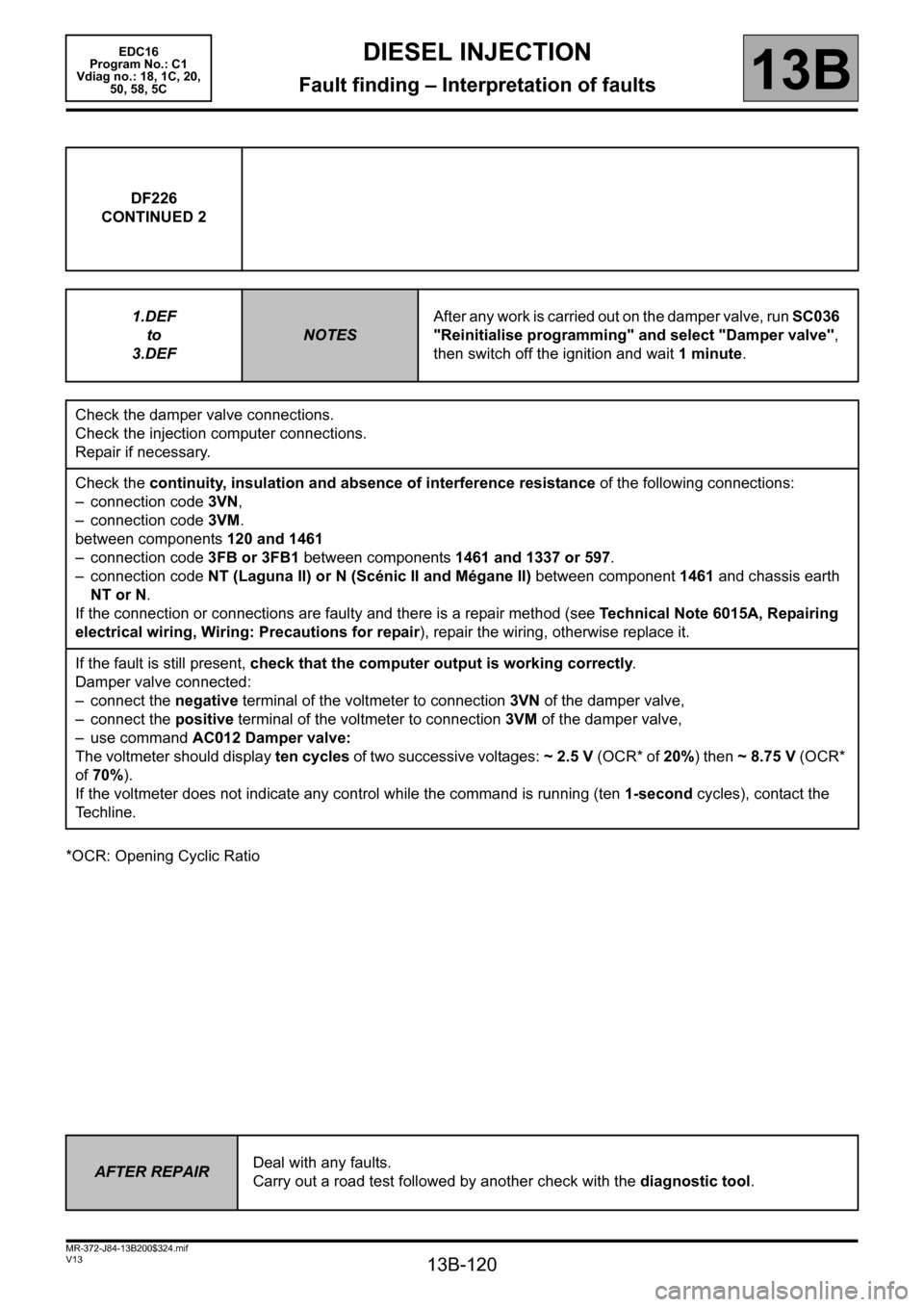
*OCR: Opening Cyclic RatioDF226
CONTINUED 2
1.DEF
to
3.DEF
NOTESAfter any work is carried out on the damper valve, run SC036
"Reinitialise programming" and select "Damper valve",
then switch off the ignition and wait 1 minute.
Check the damper valve connections.
Check the injection computer connections.
Repair if necessary.
Check the continuity, insulation and absence of interference resistance of the following connections:
– connection code 3VN,
– connection code 3VM.
between components 120 and 1461
– connection code 3FB or 3FB1 between components 1461 and 1337 or 597.
– connection code NT (Laguna II) or N (Scénic II and Mégane II) between component 1461 and chassis earth
NT or N.
If the connection or connections are faulty and there is a repair method (see Technical Note 6015A, Repairing
electrical wiring, Wiring: Precautions for repair), repair the wiring, otherwise replace it.
If the fault is still present, check that the computer output is working correctly.
Damper valve connected:
– connect the negative terminal of the voltmeter to connection 3VN of the damper valve,
– connect the positive terminal of the voltmeter to connection 3VM of the damper valve,
– use command AC012 Damper valve:
The voltmeter should display ten cycles of two successive voltages: ~2.5V (OCR* of 20%) then ~8.75V (OCR*
of 70%).
If the voltmeter does not indicate any control while the command is running (ten 1-second cycles), contact the
Techline.
AFTER REPAIRDeal with any faults.
Carry out a road test followed by another check with the diagnostic tool.
Page 128 of 365
13B-128
MR-372-J84-13B200$360.mif
V13
DIESEL INJECTION
Fault finding – Interpretation of faults
EDC16
Program No.: C1
Vdiag no.: 18, 1C, 20,
50, 58, 5C
13B
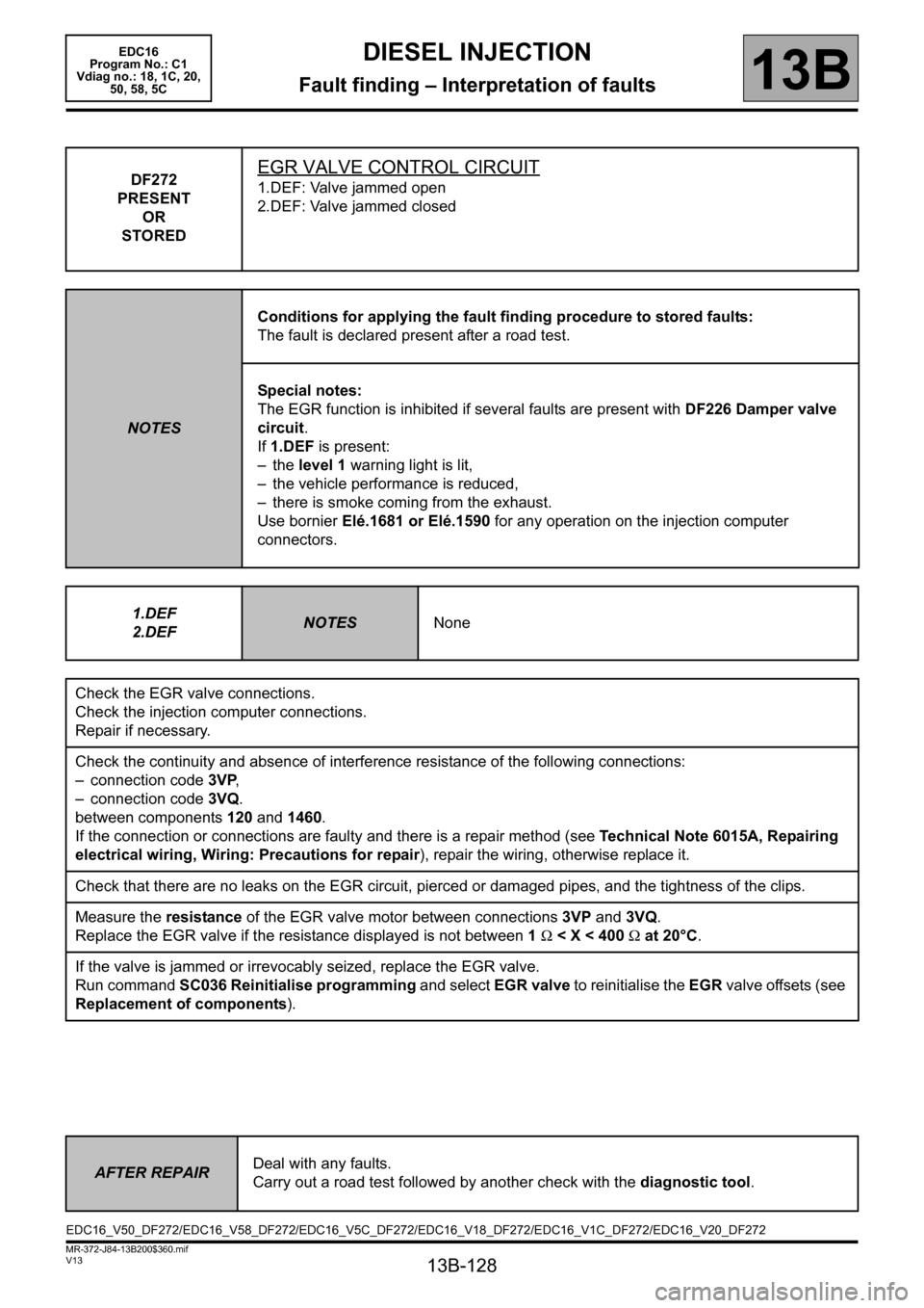
DF272
PRESENT
OR
STOREDEGR VALVE CONTROL CIRCUIT
1.DEF: Valve jammed open
2.DEF: Valve jammed closed
NOTESConditions for applying the fault finding procedure to stored faults:
The fault is declared present after a road test.
Special notes:
The EGR function is inhibited if several faults are present with DF226 Damper valve
circuit.
If 1.DEF is present:
– the level 1 warning light is lit,
– the vehicle performance is reduced,
– there is smoke coming from the exhaust.
Use bornier Elé.1681 or Elé.1590 for any operation on the injection computer
connectors.
1.DEF
2.DEF
NOTESNone
Check the EGR valve connections.
Check the injection computer connections.
Repair if necessary.
Check the continuity and absence of interference resistance of the following connections:
– connection code 3VP,
– connection code 3VQ.
between components 120 and 1460.
If the connection or connections are faulty and there is a repair method (see Technical Note 6015A, Repairing
electrical wiring, Wiring: Precautions for repair), repair the wiring, otherwise replace it.
Check that there are no leaks on the EGR circuit, pierced or damaged pipes, and the tightness of the clips.
Measure the resistance of the EGR valve motor between connections 3VP and 3VQ.
Replace the EGR valve if the resistance displayed is not between 1 Ω < X < 400 Ω at 20°C.
If the valve is jammed or irrevocably seized, replace the EGR valve.
Run command SC036 Reinitialise programming and select EGR valve to reinitialise the EGR valve offsets (see
Replacement of components).
AFTER REPAIRDeal with any faults.
Carry out a road test followed by another check with the diagnostic tool.
EDC16_V50_DF272/EDC16_V58_DF272/EDC16_V5C_DF272/EDC16_V18_DF272/EDC16_V1C_DF272/EDC16_V20_DF272
Page 131 of 365
13B-131
MR-372-J84-13B200$360.mif
V13
DIESEL INJECTION
Fault finding – Interpretation of faults
EDC16
Program No.: C1
Vdiag no.: 18, 1C, 20,
50, 58, 5C
13B
* diff.: differential
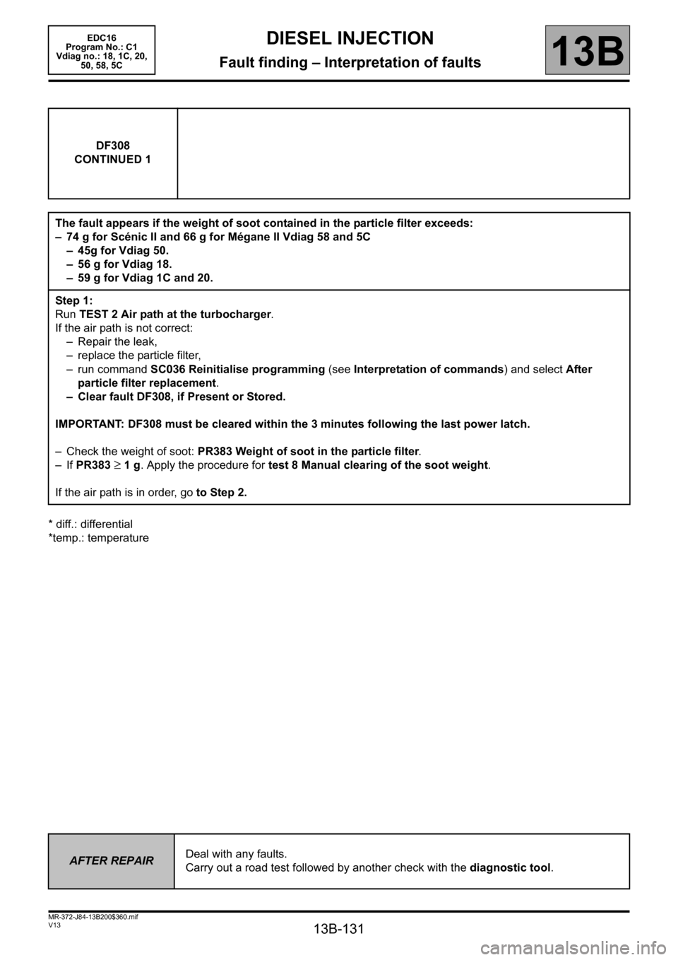
*temp.: temperatureDF308
CONTINUED 1
The fault appears if the weight of soot contained in the particle filter exceeds:
– 74 g for Scénic II and 66 g for Mégane II Vdiag 58 and 5C
– 45g for Vdiag 50.
–56 g for Vdiag 18.
– 59 g for Vdiag 1C and 20.
Step 1:
Run TEST 2 Air path at the turbocharger.
If the air path is not correct:
– Repair the leak,
– replace the particle filter,
– run command SC036 Reinitialise programming (see Interpretation of commands) and select After
particle filter replacement.
– Clear fault DF308, if Present or Stored.
IMPORTANT: DF308 must be cleared within the 3 minutes following the last power latch.
– Check the weight of soot: PR383 Weight of soot in the particle filter.
– If PR383
≥ 1 g. Apply the procedure for test 8 Manual clearing of the soot weight.
If the air path is in order, go to Step 2.
AFTER REPAIRDeal with any faults.
Carry out a road test followed by another check with the diagnostic tool.
Page 132 of 365
13B-132
MR-372-J84-13B200$360.mif
V13
DIESEL INJECTION
Fault finding – Interpretation of faults
EDC16
Program No.: C1
Vdiag no.: 18, 1C, 20,
50, 58, 5C
13B
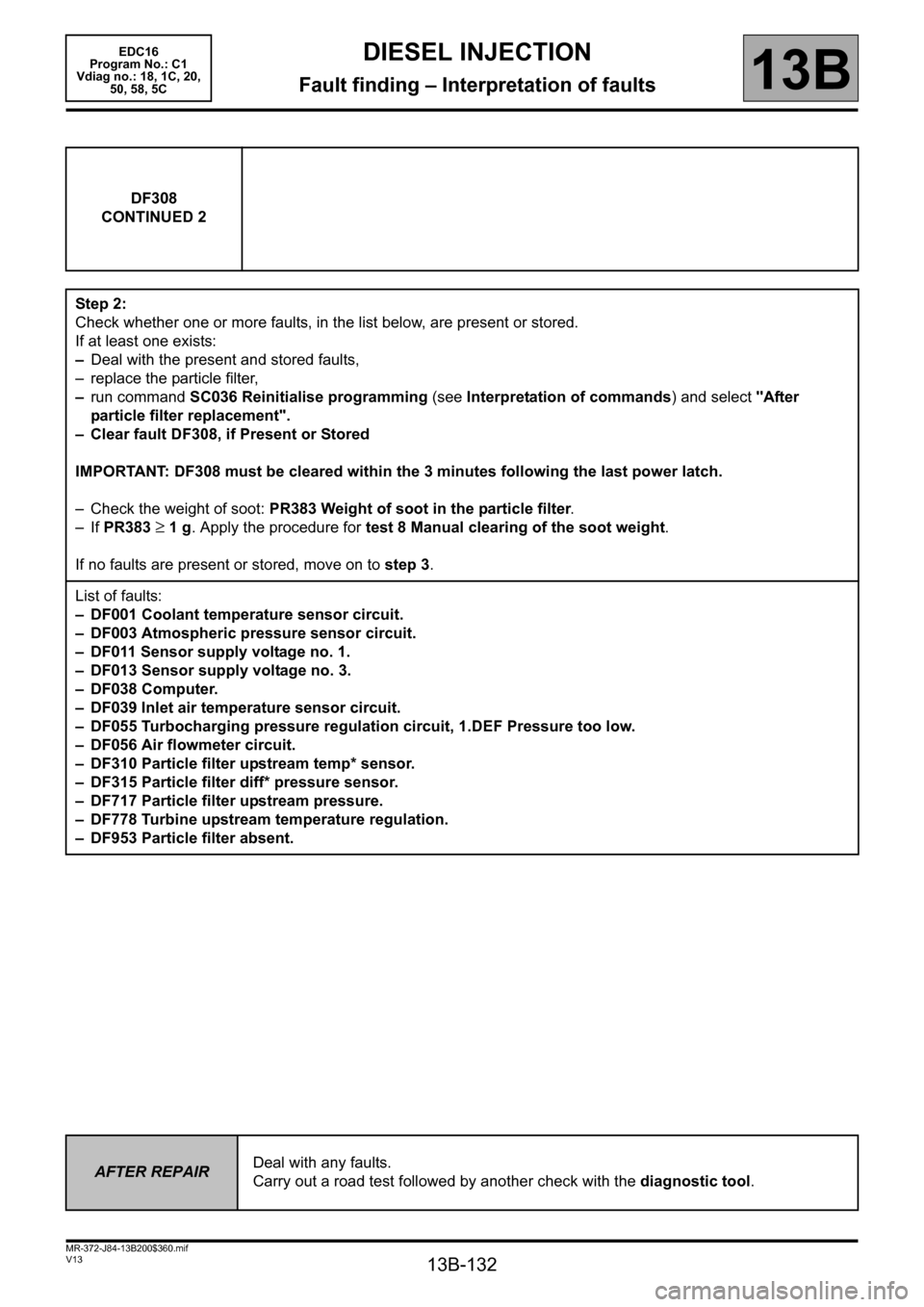
DF308
CONTINUED 2
Step 2:
Check whether one or more faults, in the list below, are present or stored.
If at least one exists:
–Deal with the present and stored faults,
– replace the particle filter,
–run command SC036 Reinitialise programming (see Interpretation of commands) and select "After
particle filter replacement".
– Clear fault DF308, if Present or Stored
IMPORTANT: DF308 must be cleared within the 3 minutes following the last power latch.
– Check the weight of soot: PR383 Weight of soot in the particle filter.
– If PR383
≥ 1 g. Apply the procedure for test 8 Manual clearing of the soot weight.
If no faults are present or stored, move on to step 3.
List of faults:
– DF001 Coolant temperature sensor circuit.
– DF003 Atmospheric pressure sensor circuit.
– DF011 Sensor supply voltage no. 1.
– DF013 Sensor supply voltage no. 3.
– DF038 Computer.
– DF039 Inlet air temperature sensor circuit.
– DF055 Turbocharging pressure regulation circuit, 1.DEF Pressure too low.
– DF056 Air flowmeter circuit.
– DF310 Particle filter upstream temp* sensor.
– DF315 Particle filter diff* pressure sensor.
– DF717 Particle filter upstream pressure.
– DF778 Turbine upstream temperature regulation.
– DF953 Particle filter absent.
AFTER REPAIRDeal with any faults.
Carry out a road test followed by another check with the diagnostic tool.
Page 142 of 365
13B-142
MR-372-J84-13B200$360.mif
V13
DIESEL INJECTION
Fault finding – Interpretation of faults
EDC16
Program No.: C1
Vdiag no.: 18, 1C, 20,
50, 58, 5C
13B
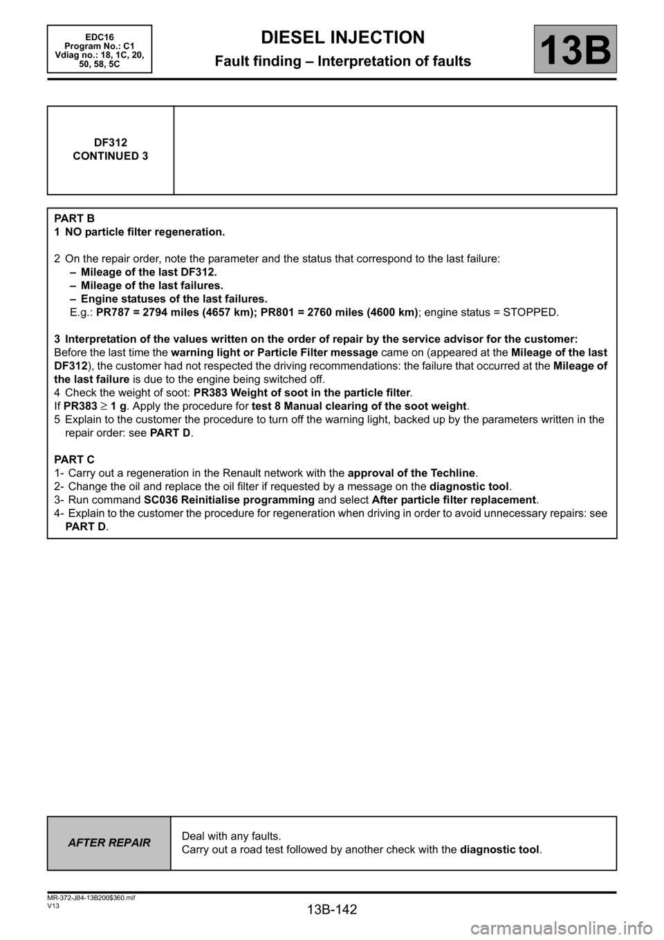
DF312
CONTINUED 3
PA R T B
1 NO particle filter regeneration.
2 On the repair order, note the parameter and the status that correspond to the last failure:
– Mileage of the last DF312.
– Mileage of the last failures.
– Engine statuses of the last failures.
E.g.: PR787 = 2794 miles (4657 km); PR801 = 2760 miles (4600 km); engine status = STOPPED.
3 Interpretation of the values written on the order of repair by the service advisor for the customer:
Before the last time the warning light or Particle Filter message came on (appeared at the Mileage of the last
DF312), the customer had not respected the driving recommendations: the failure that occurred at the Mileage of
the last failure is due to the engine being switched off.
4 Check the weight of soot: PR383 Weight of soot in the particle filter.
If PR383
≥ 1 g. Apply the procedure for test 8 Manual clearing of the soot weight.
5 Explain to the customer the procedure to turn off the warning light, backed up by the parameters written in the
repair order: see PART D.
PA R T C
1- Carry out a regeneration in the Renault network with the approval of the Techline.
2- Change the oil and replace the oil filter if requested by a message on the diagnostic tool.
3- Run command SC036 Reinitialise programming and select After particle filter replacement.
4- Explain to the customer the procedure for regeneration when driving in order to avoid unnecessary repairs: see
PART D.
AFTER REPAIRDeal with any faults.
Carry out a road test followed by another check with the diagnostic tool.
Page 149 of 365
13B-149
MR-372-J84-13B200$360.mif
V13
DIESEL INJECTION
Fault finding – Interpretation of faults
EDC16
Program No.: C1
Vdiag no.: 18, 1C, 20,
50, 58, 5C
13B
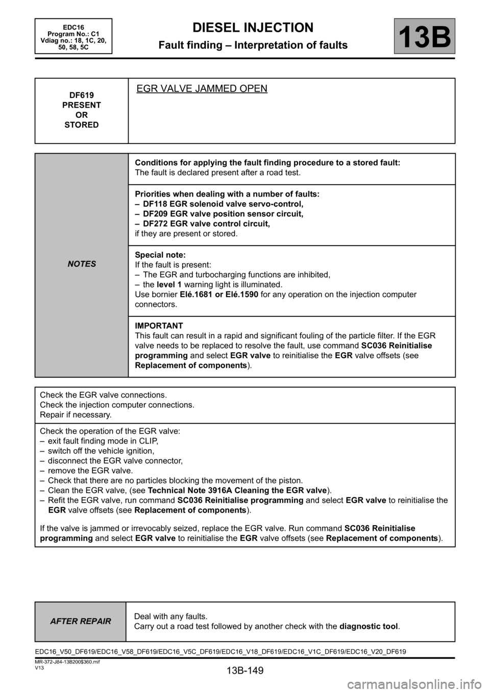
DF619
PRESENT
OR
STOREDEGR VALVE JAMMED OPEN
NOTESConditions for applying the fault finding procedure to a stored fault:
The fault is declared present after a road test.
Priorities when dealing with a number of faults:
– DF118 EGR solenoid valve servo-control,
– DF209 EGR valve position sensor circuit,
– DF272 EGR valve control circuit,
if they are present or stored.
Special note:
If the fault is present:
– The EGR and turbocharging functions are inhibited,
– the level 1 warning light is illuminated.
Use bornier Elé.1681 or Elé.1590 for any operation on the injection computer
connectors.
IMPORTANT
This fault can result in a rapid and significant fouling of the particle filter. If the EGR
valve needs to be replaced to resolve the fault, use command SC036 Reinitialise
programming and select EGR valve to reinitialise the EGR valve offsets (see
Replacement of components).
Check the EGR valve connections.
Check the injection computer connections.
Repair if necessary.
Check the operation of the EGR valve:
– exit fault finding mode in CLIP,
– switch off the vehicle ignition,
– disconnect the EGR valve connector,
– remove the EGR valve.
– Check that there are no particles blocking the movement of the piston.
– Clean the EGR valve, (see Technical Note 3916A Cleaning the EGR valve).
– Refit the EGR valve, run command SC036 Reinitialise programming and select EGR valve to reinitialise the
EGR valve offsets (see Replacement of components).
If the valve is jammed or irrevocably seized, replace the EGR valve. Run command SC036 Reinitialise
programming and select EGR valve to reinitialise the EGR valve offsets (see Replacement of components).
AFTER REPAIRDeal with any faults.
Carry out a road test followed by another check with the diagnostic tool.
EDC16_V50_DF619/EDC16_V58_DF619/EDC16_V5C_DF619/EDC16_V18_DF619/EDC16_V1C_DF619/EDC16_V20_DF619
Page 150 of 365
13B-150
MR-372-J84-13B200$360.mif
V13
DIESEL INJECTION
Fault finding – Interpretation of faults
EDC16
Program No.: C1
Vdiag no.: 18, 1C, 20,
50, 58, 5C
13B
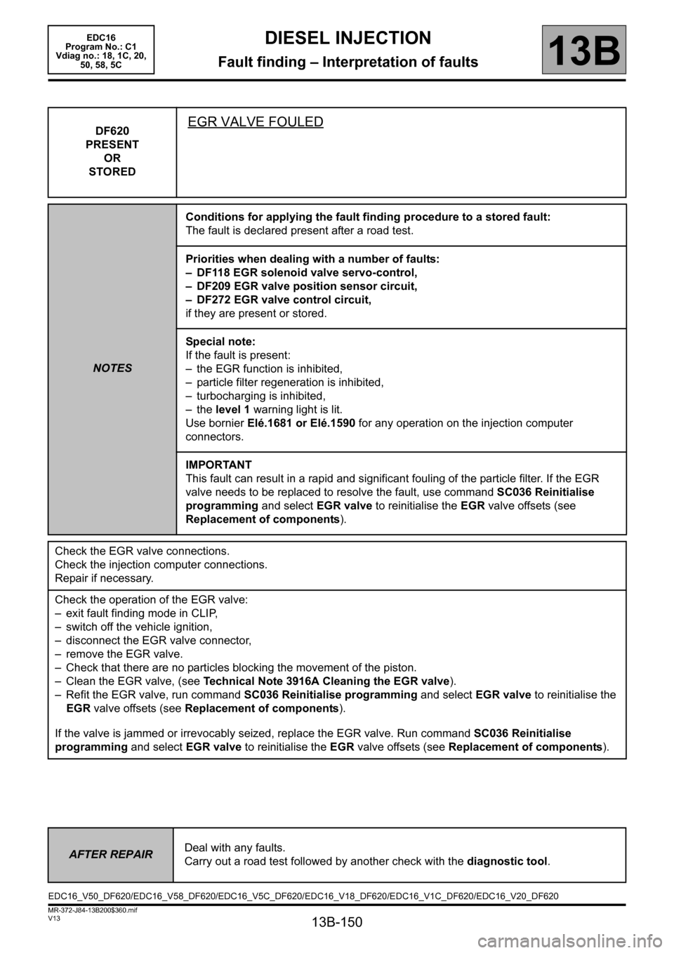
DF620
PRESENT
OR
STOREDEGR VALVE FOULED
NOTESConditions for applying the fault finding procedure to a stored fault:
The fault is declared present after a road test.
Priorities when dealing with a number of faults:
– DF118 EGR solenoid valve servo-control,
– DF209 EGR valve position sensor circuit,
– DF272 EGR valve control circuit,
if they are present or stored.
Special note:
If the fault is present:
– the EGR function is inhibited,
– particle filter regeneration is inhibited,
– turbocharging is inhibited,
– the level 1 warning light is lit.
Use bornier Elé.1681 or Elé.1590 for any operation on the injection computer
connectors.
IMPORTANT
This fault can result in a rapid and significant fouling of the particle filter. If the EGR
valve needs to be replaced to resolve the fault, use command SC036 Reinitialise
programming and select EGR valve to reinitialise the EGR valve offsets (see
Replacement of components).
Check the EGR valve connections.
Check the injection computer connections.
Repair if necessary.
Check the operation of the EGR valve:
– exit fault finding mode in CLIP,
– switch off the vehicle ignition,
– disconnect the EGR valve connector,
– remove the EGR valve.
– Check that there are no particles blocking the movement of the piston.
– Clean the EGR valve, (see Technical Note 3916A Cleaning the EGR valve).
– Refit the EGR valve, run command SC036 Reinitialise programming and select EGR valve to reinitialise the
EGR valve offsets (see Replacement of components).
If the valve is jammed or irrevocably seized, replace the EGR valve. Run command SC036 Reinitialise
programming and select EGR valve to reinitialise the EGR valve offsets (see Replacement of components).
AFTER REPAIRDeal with any faults.
Carry out a road test followed by another check with the diagnostic tool.
EDC16_V50_DF620/EDC16_V58_DF620/EDC16_V5C_DF620/EDC16_V18_DF620/EDC16_V1C_DF620/EDC16_V20_DF620
Page 151 of 365
13B-151
MR-372-J84-13B200$360.mif
V13
DIESEL INJECTION
Fault finding – Interpretation of faults
EDC16
Program No.: C1
Vdiag no.: 18, 1C, 20,
50, 58, 5C
13B
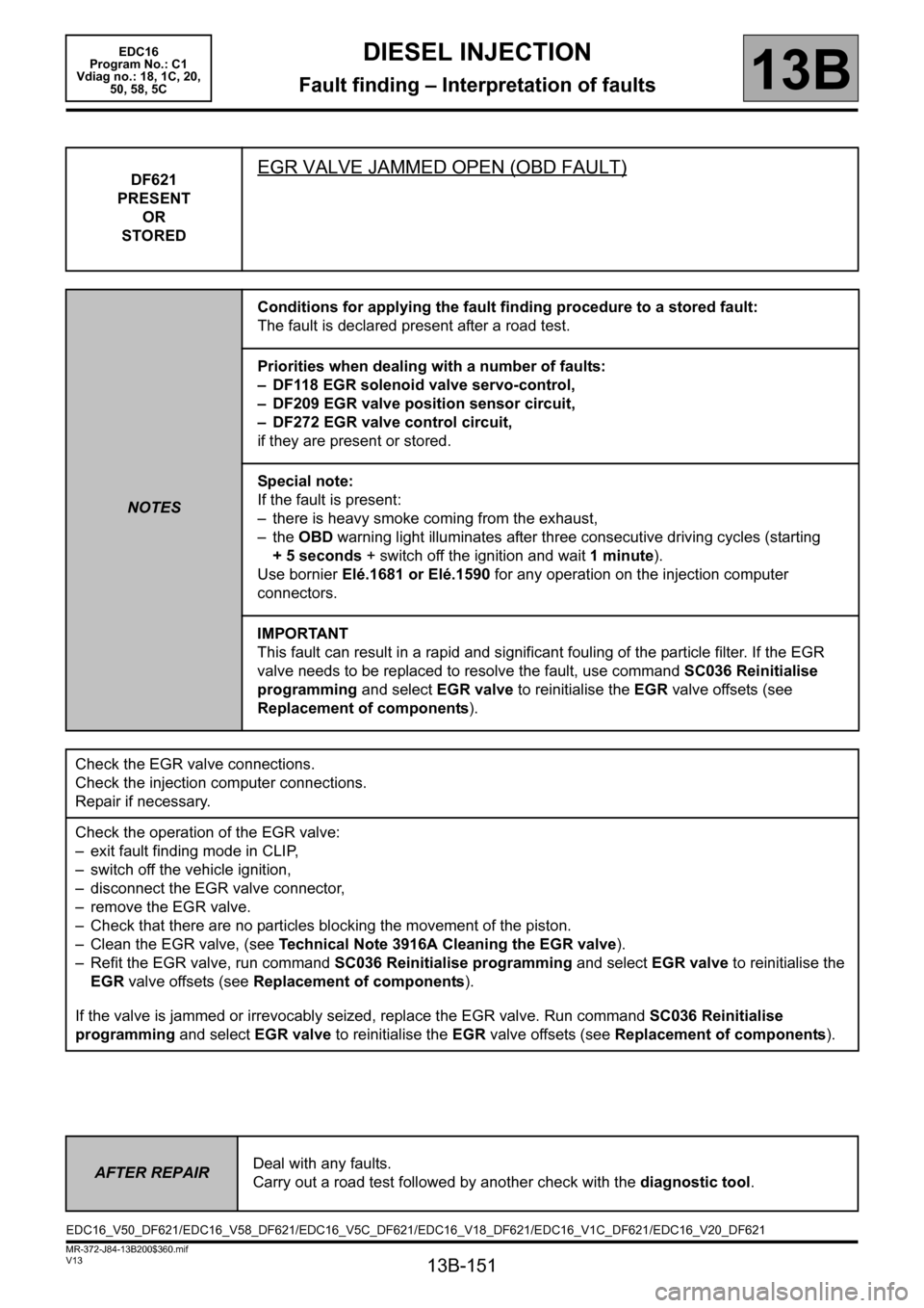
DF621
PRESENT
OR
STOREDEGR VALVE JAMMED OPEN (OBD FAULT)
NOTESConditions for applying the fault finding procedure to a stored fault:
The fault is declared present after a road test.
Priorities when dealing with a number of faults:
– DF118 EGR solenoid valve servo-control,
– DF209 EGR valve position sensor circuit,
– DF272 EGR valve control circuit,
if they are present or stored.
Special note:
If the fault is present:
– there is heavy smoke coming from the exhaust,
– the OBD warning light illuminates after three consecutive driving cycles (starting
+ 5 seconds + switch off the ignition and wait 1 minute).
Use bornier Elé.1681 or Elé.1590 for any operation on the injection computer
connectors.
IMPORTANT
This fault can result in a rapid and significant fouling of the particle filter. If the EGR
valve needs to be replaced to resolve the fault, use command SC036 Reinitialise
programming and select EGR valve to reinitialise the EGR valve offsets (see
Replacement of components).
Check the EGR valve connections.
Check the injection computer connections.
Repair if necessary.
Check the operation of the EGR valve:
– exit fault finding mode in CLIP,
– switch off the vehicle ignition,
– disconnect the EGR valve connector,
– remove the EGR valve.
– Check that there are no particles blocking the movement of the piston.
– Clean the EGR valve, (see Technical Note 3916A Cleaning the EGR valve).
– Refit the EGR valve, run command SC036 Reinitialise programming and select EGR valve to reinitialise the
EGR valve offsets (see Replacement of components).
If the valve is jammed or irrevocably seized, replace the EGR valve. Run command SC036 Reinitialise
programming and select EGR valve to reinitialise the EGR valve offsets (see Replacement of components).
AFTER REPAIRDeal with any faults.
Carry out a road test followed by another check with the diagnostic tool.
EDC16_V50_DF621/EDC16_V58_DF621/EDC16_V5C_DF621/EDC16_V18_DF621/EDC16_V1C_DF621/EDC16_V20_DF621
Page 157 of 365
13B-157
MR-372-J84-13B200$360.mif
V13
DIESEL INJECTION
Fault finding – Interpretation of faults
EDC16
Program No.: C1
Vdiag no.: 18, 1C, 20,
50, 58, 5C
13B
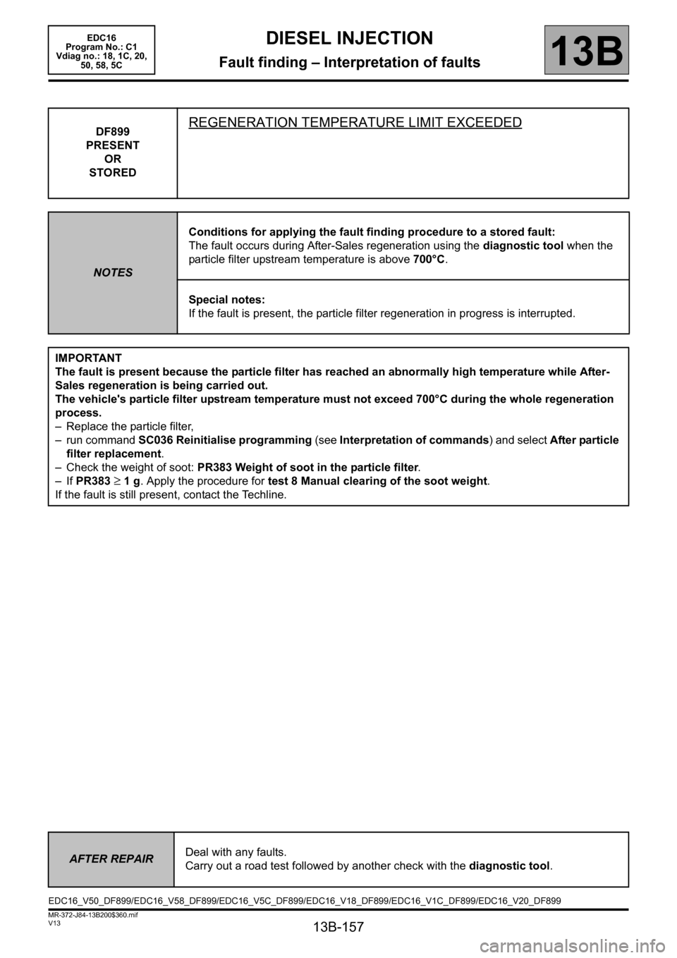
DF899
PRESENT
OR
STOREDREGENERATION TEMPERATURE LIMIT EXCEEDED
NOTESConditions for applying the fault finding procedure to a stored fault:
The fault occurs during After-Sales regeneration using the diagnostic tool when the
particle filter upstream temperature is above 700°C.
Special notes:
If the fault is present, the particle filter regeneration in progress is interrupted.
IMPORTANT
The fault is present because the particle filter has reached an abnormally high temperature while After-
Sales regeneration is being carried out.
The vehicle's particle filter upstream temperature must not exceed 700°C during the whole regeneration
process.
– Replace the particle filter,
– run command SC036 Reinitialise programming (see Interpretation of commands) and select After particle
filter replacement.
– Check the weight of soot: PR383 Weight of soot in the particle filter.
– If PR383
≥ 1 g. Apply the procedure for test 8 Manual clearing of the soot weight.
If the fault is still present, contact the Techline.
AFTER REPAIRDeal with any faults.
Carry out a road test followed by another check with the diagnostic tool.
EDC16_V50_DF899/EDC16_V58_DF899/EDC16_V5C_DF899/EDC16_V18_DF899/EDC16_V1C_DF899/EDC16_V20_DF899