air filter RENAULT SCENIC 2011 J95 / 3.G Engine And Peripherals Siemens Injection Repair Manual
[x] Cancel search | Manufacturer: RENAULT, Model Year: 2011, Model line: SCENIC, Model: RENAULT SCENIC 2011 J95 / 3.GPages: 329, PDF Size: 1.71 MB
Page 300 of 329

13B-300
MR-372-J84-13B050$897.mif
V17
DIESEL INJECTION
Fault finding – Fault Finding Chart
Siemens Injection
SID301 and 304
Vdiag No.: 44-45-48-49-4D-4C
Program No.: B1 and B2
13B
ALP 21
CONTINUED 2
Check the air flow:
●The air flow must be approximately 250 mg/st.
Check the air flowmeter connector, component code 799 (corrosion, fouling, etc.).
If the connector is faulty and there is a repair method (see Technical Note 6015A, Repairing electrical wiring,
Wiring: Precautions for repair), repair the connector(s), otherwise replace the wiring.
Check the continuity, insulation and absence of interference resistance on the following connections:
●Code connection 3FB (3FB3 for Kangoo II) between components 799 and 1768.
●Connection code 3ABQ between components 799 and 120.
●Connection code 3DV between components 799 and 120.
●Connection code 3KJ between components 799 and 120.
●connection code 3DW between components 799 and 120.
If the connection or connections are faulty and there is a repair procedure (see Technical Note 6015A, Electrical
wiring repair, Wiring: Precautions for repair), repair the wiring, otherwise replace it.
Check the particle filter injector supply system by running Test 8 Particle filter injector supply circuit check.
AFTER REPAIRCarry out a road test followed by a complete check with the diagnostic tool.
Page 301 of 329
13B-301
MR-372-J84-13B050$936.mif
V17
13B
DIESEL INJECTION
Fault finding – Tests
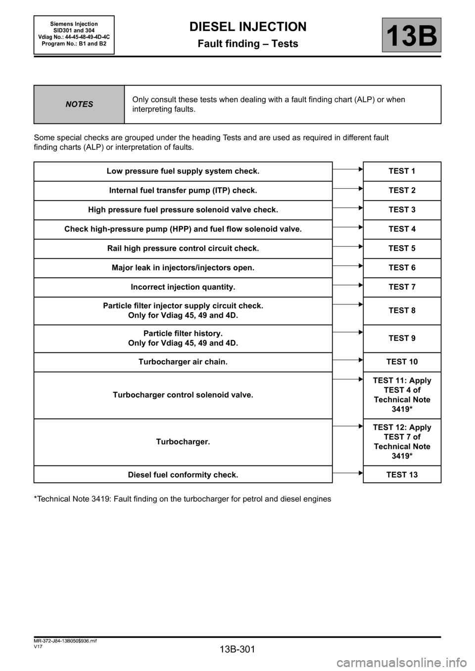
Some special checks are grouped under the heading Tests and are used as required in different fault
finding charts (ALP) or interpretation of faults.
*Technical Note 3419: Fault finding on the turbocharger for petrol and diesel engines
NOTESOnly consult these tests when dealing with a fault finding chart (ALP) or when
interpreting faults.
Low pressure fuel supply system check. TEST 1
Internal fuel transfer pump (ITP) check. TEST 2
High pressure fuel pressure solenoid valve check. TEST 3
Check high-pressure pump (HPP) and fuel flow solenoid valve. TEST 4
Rail high pressure control circuit check. TEST 5
Major leak in injectors/injectors open. TEST 6
Incorrect injection quantity. TEST 7
Particle filter injector supply circuit check.
Only for Vdiag 45, 49 and 4D.TEST 8
Particle filter history.
Only for Vdiag 45, 49 and 4D.TEST 9
Turbocharger air chain. TEST 10
Turbocharger control solenoid valve.TEST 11: Apply
TEST 4 of
Technical Note
3419*
Turbocharger.TEST 12: Apply
TEST 7 of
Technical Note
3419*
Diesel fuel conformity check. TEST 13
MR-372-J84-13B050$936.mif
Siemens Injection
SID301 and 304
Vdiag No.: 44-45-48-49-4D-4CProgram No.: B1 and B2
Page 302 of 329
13B-302
MR-372-J84-13B050$936.mif
V17
DIESEL INJECTION
Fault finding – Tests13B
Siemens Injection
SID301 and 304
Vdiag No.: 44-45-48-49-4D-4C
Program No.: B1 and B2
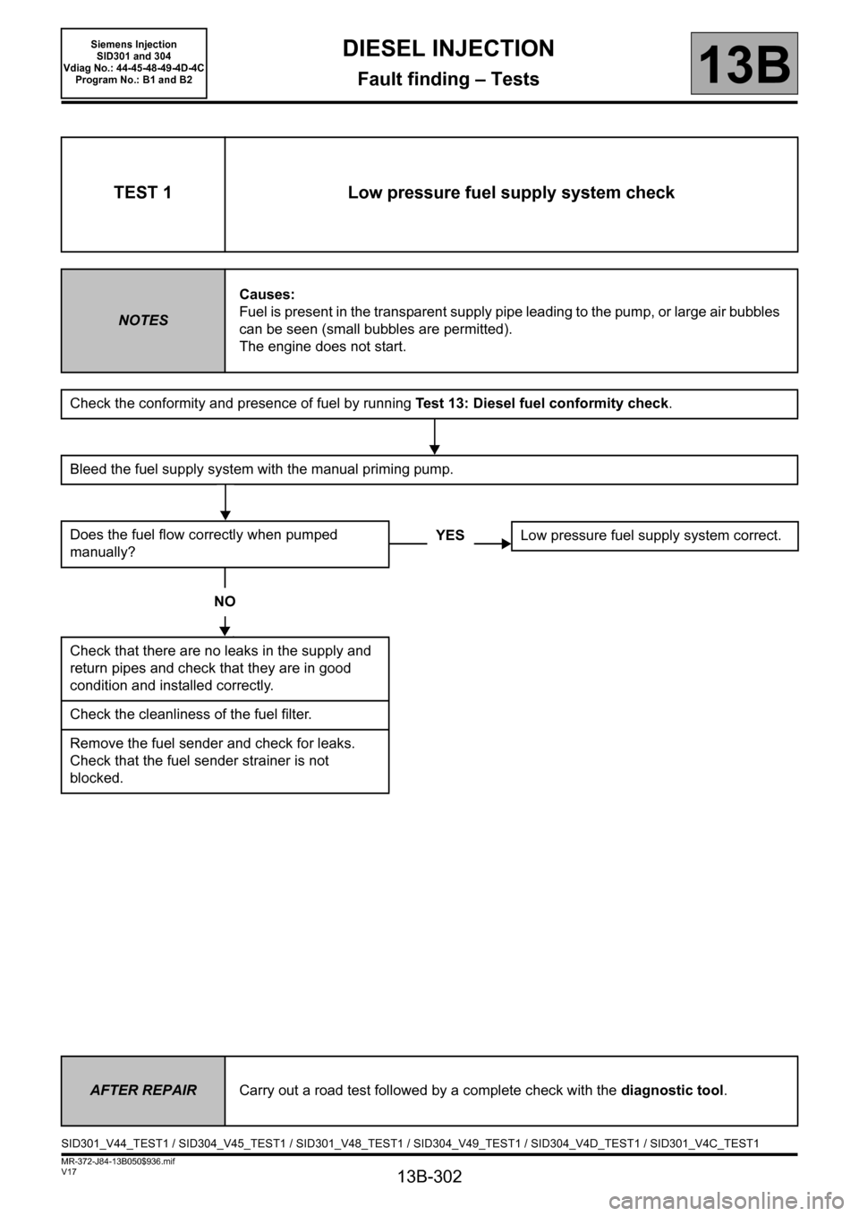
TEST 1 Low pressure fuel supply system check
NOTESCauses:
Fuel is present in the transparent supply pipe leading to the pump, or large air bubbles
can be seen (small bubbles are permitted).
The engine does not start.
Check the conformity and presence of fuel by running Test 13: Diesel fuel conformity check.
Bleed the fuel supply system with the manual priming pump.
Does the fuel flow correctly when pumped
manually?
NO
Check that there are no leaks in the supply and
return pipes and check that they are in good
condition and installed correctly.
Check the cleanliness of the fuel filter.
Remove the fuel sender and check for leaks.
Check that the fuel sender strainer is not
blocked.
YESLow pressure fuel supply system correct.
AFTER REPAIRCarry out a road test followed by a complete check with the diagnostic tool.
SID301_V44_TEST1 / SID304_V45_TEST1 / SID301_V48_TEST1 / SID304_V49_TEST1 / SID304_V4D_TEST1 / SID301_V4C_TEST1
Page 308 of 329
13B-308
MR-372-J84-13B050$936.mif
V17
DIESEL INJECTION
Fault finding – Tests13B
Siemens Injection
SID301 and 304
Vdiag No.: 44-45-48-49-4D-4C
Program No.: B1 and B2
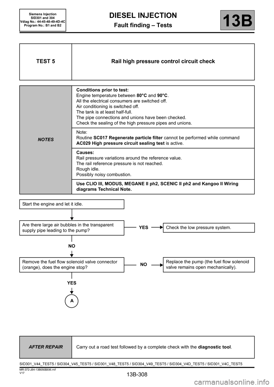
TEST 5 Rail high pressure control circuit check
NOTESConditions prior to test:
Engine temperature between 80°C and 90°C.
All the electrical consumers are switched off.
Air conditioning is switched off.
The tank is at least half-full.
The pipe connections and unions have been checked.
Check the sealing of the high pressure pipes and unions.
Note:
Routine SC017 Regenerate particle filter cannot be performed while command
AC029 High pressure circuit sealing test is active.
Causes:
Rail pressure variations around the reference value.
The rail reference pressure is not reached.
Rough idle.
Possibly noisy combustion.
Use CLIO III, MODUS, MEGANE II ph2, SCENIC II ph2 and Kangoo II Wiring
diagrams Technical Note.
Start the engine and let it idle.
Are there large air bubbles in the transparent
supply pipe leading to the pump?
NO
Remove the fuel flow solenoid valve connector
(orange), does the engine stop?
YES
YESCheck the low pressure system.
NOReplace the pump (the fuel flow solenoid
valve remains open mechanically).
AFTER REPAIRCarry out a road test followed by a complete check with the diagnostic tool.
SID301_V44_TEST5 / SID304_V45_TEST5 / SID301_V48_TEST5 / SID304_V49_TEST5 / SID304_V4D_TEST5 / SID301_V4C_TEST5
A
Page 318 of 329
13B-318
MR-372-J84-13B050$936.mif
V17
DIESEL INJECTION
Fault finding – Tests13B
Siemens Injection
SID301 and 304
Vdiag No.: 44-45-48-49-4D-4C
Program No.: B1 and B2
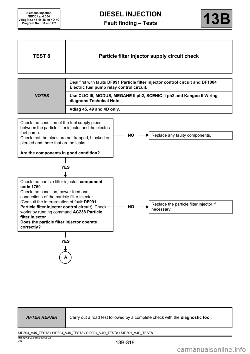
TEST 8 Particle filter injector supply circuit check
NOTESDeal first with faults DF991 Particle filter injector control circuit and DF1004
Electric fuel pump relay control circuit.
Use CLIO III, MODUS, MEGANE II ph2, SCENIC II ph2 and Kangoo II Wiring
diagrams Technical Note.
Vdiag 45, 49 and 4D only.
Check the condition of the fuel supply pipes
between the particle filter injector and the electric
fuel pump.
Check that the pipes are not trapped, blocked or
pierced and there that are no leaks.
Are the components in good condition?
YES
Check the particle filter injector, component
code 1750.
Check the condition, power feed and
connections of the particle filter injector.
(Consult the interpretation of fault DF991
Particle filter injector control circuit). Check it
works by running command AC238 Particle
filter injector.
Does the particle filter injector operate
correctly?
YES
NOReplace any faulty components.
NOReplace the particle filter injector if
necessary.
AFTER REPAIRCarry out a road test followed by a complete check with the diagnostic tool.
SID304_V45_TEST8 / SID304_V49_TEST8 / SID304_V4D_TEST8 / SID301_V4C_TEST8
A
Page 319 of 329
13B-319
MR-372-J84-13B050$936.mif
V17
DIESEL INJECTION
Fault finding – Tests
Siemens Injection
SID301 and 304
Vdiag No.: 44-45-48-49-4D-4C
Program No.: B1 and B2
13B
TEST 8
CONTINUED 1
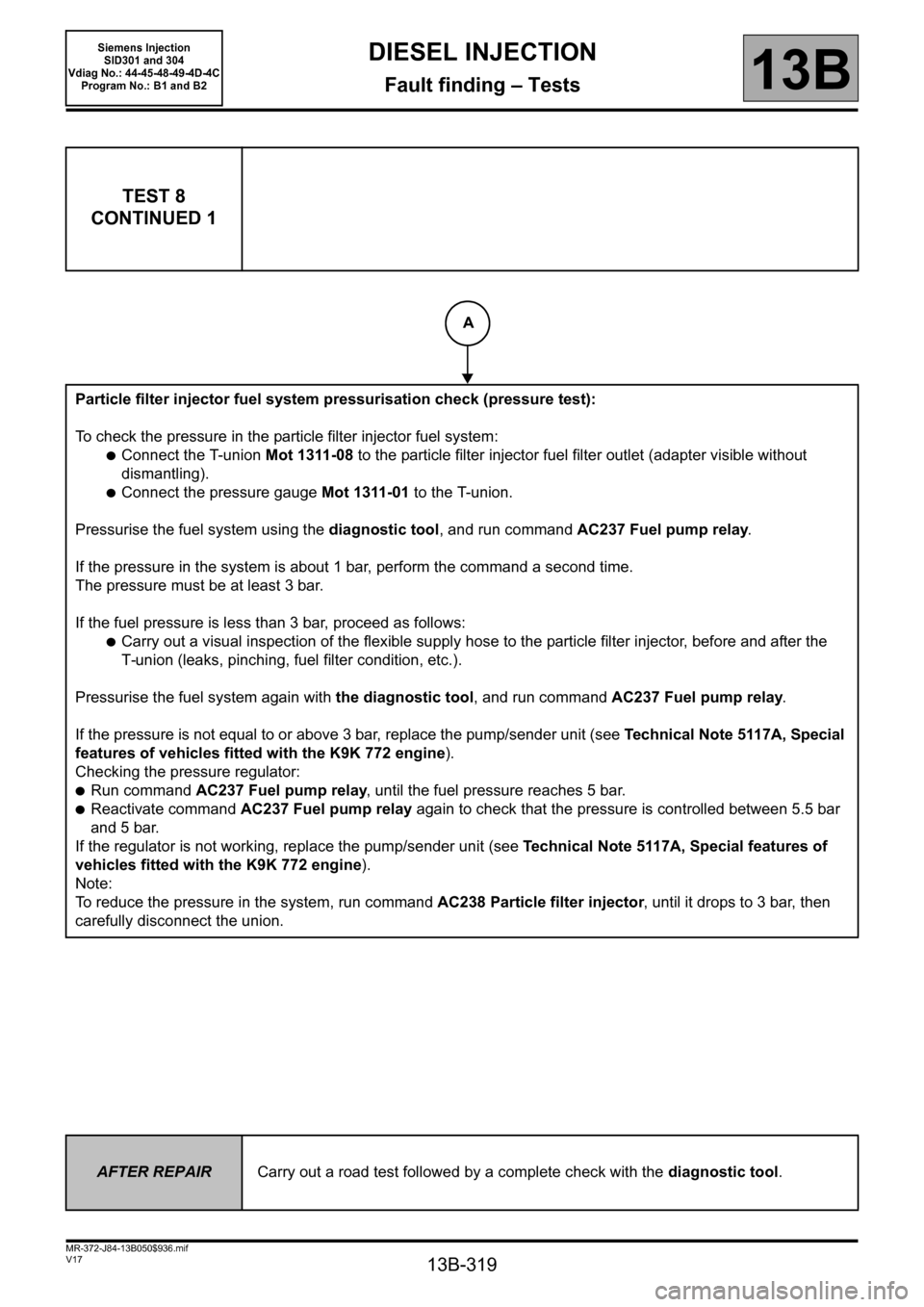
Particle filter injector fuel system pressurisation check (pressure test):
To check the pressure in the particle filter injector fuel system:
●Connect the T-union Mot 1311-08 to the particle filter injector fuel filter outlet (adapter visible without
dismantling).
●Connect the pressure gauge Mot 1311-01 to the T-union.
Pressurise the fuel system using the diagnostic tool, and run command AC237 Fuel pump relay.
If the pressure in the system is about 1 bar, perform the command a second time.
The pressure must be at least 3 bar.
If the fuel pressure is less than 3 bar, proceed as follows:
●Carry out a visual inspection of the flexible supply hose to the particle filter injector, before and after the
T-union (leaks, pinching, fuel filter condition, etc.).
Pressurise the fuel system again with the diagnostic tool, and run command AC237 Fuel pump relay.
If the pressure is not equal to or above 3 bar, replace the pump/sender unit (see Technical Note 5117A, Special
features of vehicles fitted with the K9K 772 engine).
Checking the pressure regulator:
●Run command AC237 Fuel pump relay, until the fuel pressure reaches 5 bar.
●Reactivate command AC237 Fuel pump relay again to check that the pressure is controlled between 5.5 bar
and 5 bar.
If the regulator is not working, replace the pump/sender unit (see Technical Note 5117A, Special features of
vehicles fitted with the K9K 772 engine).
Note:
To reduce the pressure in the system, run command AC238 Particle filter injector, until it drops to 3 bar, then
carefully disconnect the union.
AFTER REPAIRCarry out a road test followed by a complete check with the diagnostic tool.
A
Page 320 of 329
13B-320
MR-372-J84-13B050$936.mif
V17
DIESEL INJECTION
Fault finding – Tests
Siemens Injection
SID301 and 304
Vdiag No.: 44-45-48-49-4D-4C
Program No.: B1 and B2
13B
TEST 8
CONTINUED 2
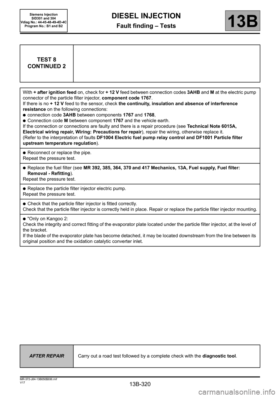
With + after ignition feed on, check for + 12 V feed between connection codes 3AHB and M at the electric pump
connector of the particle filter injector, component code 1767.
If there is no + 12 V feed to the sensor, check the continuity, insulation and absence of interference
resistance on the following connections:
●connection code 3AHB between components 1767 and 1768,
●Connection code M between component 1767 and the vehicle earth.
If the connection or connections are faulty and there is a repair procedure (see Technical Note 6015A,
Electrical wiring repair, Wiring: Precautions for repair), repair the wiring, otherwise replace it.
(Refer to the interpretation of faults DF1004 Electric fuel pump relay control and DF1001 Particle filter
upstream temperature regulation).
●Reconnect or replace the pipe.
Repeat the pressure test.
●Replace the fuel filter (see MR 392, 385, 364, 370 and 417 Mechanics, 13A, Fuel supply, Fuel filter:
Removal - Refitting).
Repeat the pressure test.
●Replace the particle filter injector electric pump.
Repeat the pressure test.
●Check that the particle filter injector is fitted correctly.
Check that the particle filter injector is correctly held in place. Repair or replace the particle filter injector mounting.
●"Only on Kangoo 2:
Check the integrity and correct fitting of the evaporator plate located under the particle filter injector, at the level of
the bracket.
If the blade of the evaporator plate has become detached, it may be located downstream from the line between its
original position and the oxidation catalytic converter inlet.
AFTER REPAIRCarry out a road test followed by a complete check with the diagnostic tool.
Page 321 of 329
13B-321
MR-372-J84-13B050$936.mif
V17
DIESEL INJECTION
Fault finding – Tests
Siemens Injection
SID301 and 304
Vdiag No.: 44-45-48-49-4D-4C
Program No.: B1 and B2
13B
TEST 9 Particle filter history
NOTESOnly address this customer complaint after a complete check with the diagnostic
tool.
Note:
The flow chart below enables the driving profile and the reasons why the warning light
illuminates to be analysed:
Vdiag 49 and 4D only.
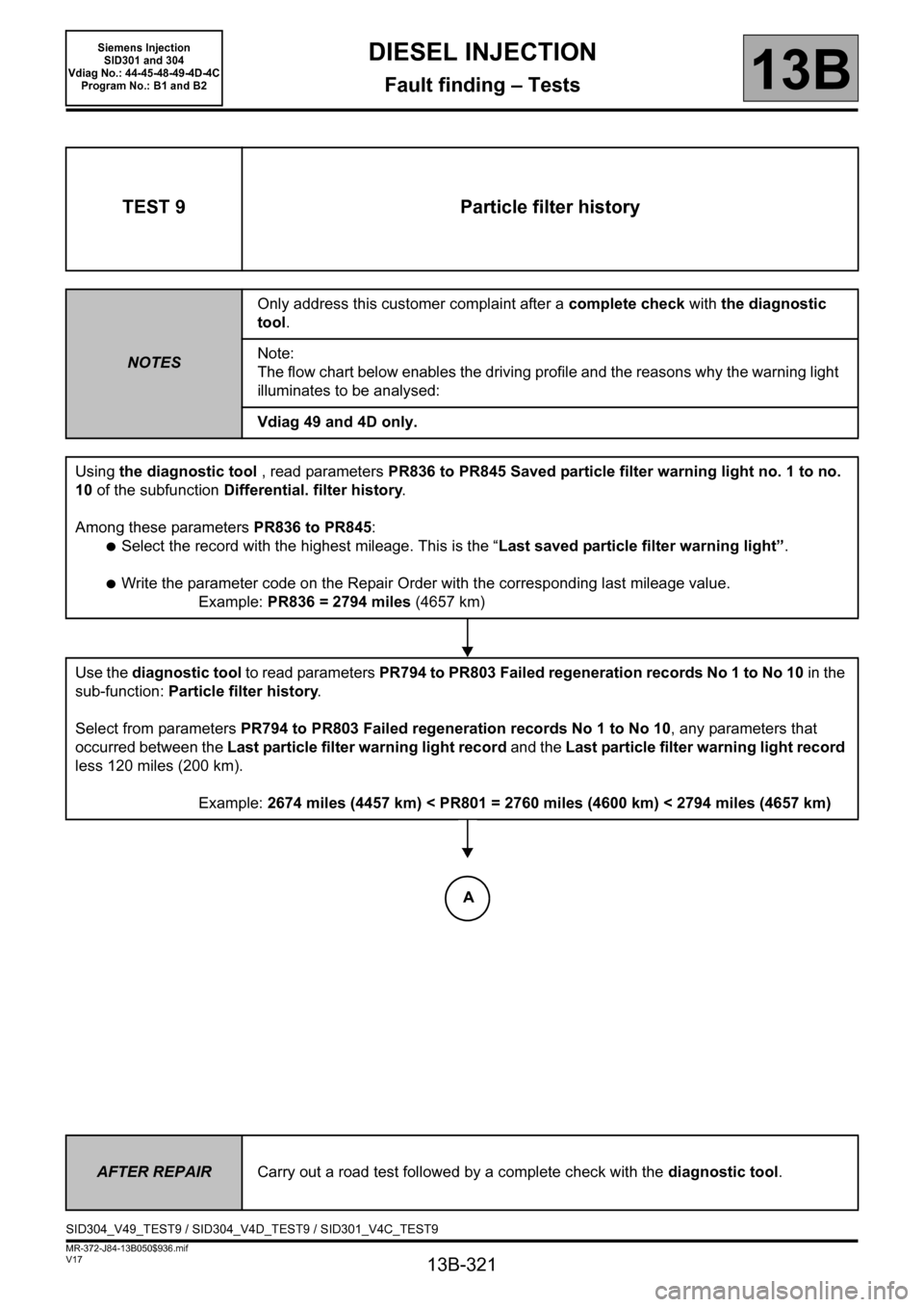
Using the diagnostic tool , read parameters PR836 to PR845 Saved particle filter warning light no. 1 to no.
10 of the subfunction Differential. filter history.
Among these parameters PR836 to PR845:
●Select the record with the highest mileage. This is the “Last saved particle filter warning light”.
●Write the parameter code on the Repair Order with the corresponding last mileage value.
Example: PR836 = 2794 miles (4657 km)
Use the diagnostic tool to read parameters PR794 to PR803 Failed regeneration records No 1 to No 10 in the
sub-function: Particle filter history.
Select from parameters PR794 to PR803 Failed regeneration records No 1 to No 10, any parameters that
occurred between the Last particle filter warning light record and the Last particle filter warning light record
less 120 miles (200 km).
Example: 2674 miles (4457 km) < PR801 = 2760 miles (4600 km) < 2794 miles (4657 km)
AFTER REPAIRCarry out a road test followed by a complete check with the diagnostic tool.
SID304_V49_TEST9 / SID304_V4D_TEST9 / SID301_V4C_TEST9
A
Page 322 of 329
13B-322
MR-372-J84-13B050$936.mif
V17
Siemens Injection
SID301 and 304
Vdiag No.: 44-45-48-49-4D-4C
Program No.: B1 and B2DIESEL INJECTION
Fault finding – Tests13B
TEST 9
CONTINUED 1
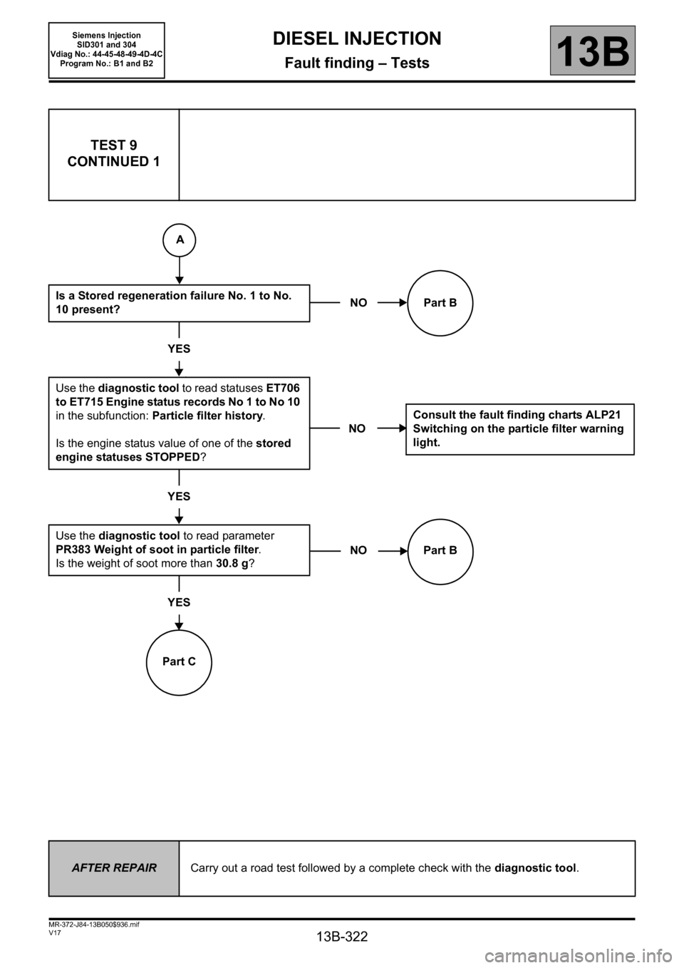
Is a Stored regeneration failure No. 1 to No.
10 present?
YES
Use the diagnostic tool to read statuses ET706
to ET715 Engine status records No 1 to No 10
in the subfunction: Particle filter history.
Is the engine status value of one of the stored
engine statuses STOPPED?
YES
Use the diagnostic tool to read parameter
PR383 Weight of soot in particle filter.
Is the weight of soot more than 30.8 g?
YES
Part CNO Part B
NOConsult the fault finding charts ALP21
Switching on the particle filter warning
light.
NO Part B
AFTER REPAIRCarry out a road test followed by a complete check with the diagnostic tool.
A
Page 323 of 329
13B-323
MR-372-J84-13B050$936.mif
V17
DIESEL INJECTION
Fault finding – Tests
Siemens Injection
SID301 and 304
Vdiag No.: 44-45-48-49-4D-4C
Program No.: B1 and B2
13B
TEST 9
CONTINUED 2
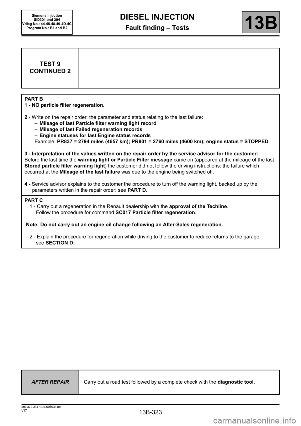
PA R T B
1 - NO particle filter regeneration.
2 - Write on the repair order: the parameter and status relating to the last failure:
– Mileage of last Particle filter warning light record
– Mileage of last Failed regeneration records
– Engine statuses for last Engine status records
Example: PR837 = 2794 miles (4657 km); PR801 = 2760 miles (4600 km); engine status = STOPPED
3 - Interpretation of the values written on the repair order by the service advisor for the customer:
Before the last time the warning light or Particle Filter message came on (appeared at the mileage of the last
Stored particle filter warning light) the customer did not follow the driving instructions: the failure which
occurred at the Mileage of the last failure was due to the engine being switched off.
4 - Service advisor explains to the customer the procedure to turn off the warning light, backed up by the
parameters written in the repair order: see PA R T D.
PA R T C
1 - Carry out a regeneration in the Renault dealership with the approval of the Techline.
Follow the procedure for command SC017 Particle filter regeneration.
Note: Do not carry out an engine oil change following an After-Sales regeneration.
2 - Explain the procedure for regeneration while driving to the customer to reduce returns to the garage:
see SECTION D:
AFTER REPAIRCarry out a road test followed by a complete check with the diagnostic tool.