abs RENAULT SCENIC 2011 J95 / 3.G Engine And Peripherals User Guide
[x] Cancel search | Manufacturer: RENAULT, Model Year: 2011, Model line: SCENIC, Model: RENAULT SCENIC 2011 J95 / 3.GPages: 198, PDF Size: 0.85 MB
Page 37 of 198
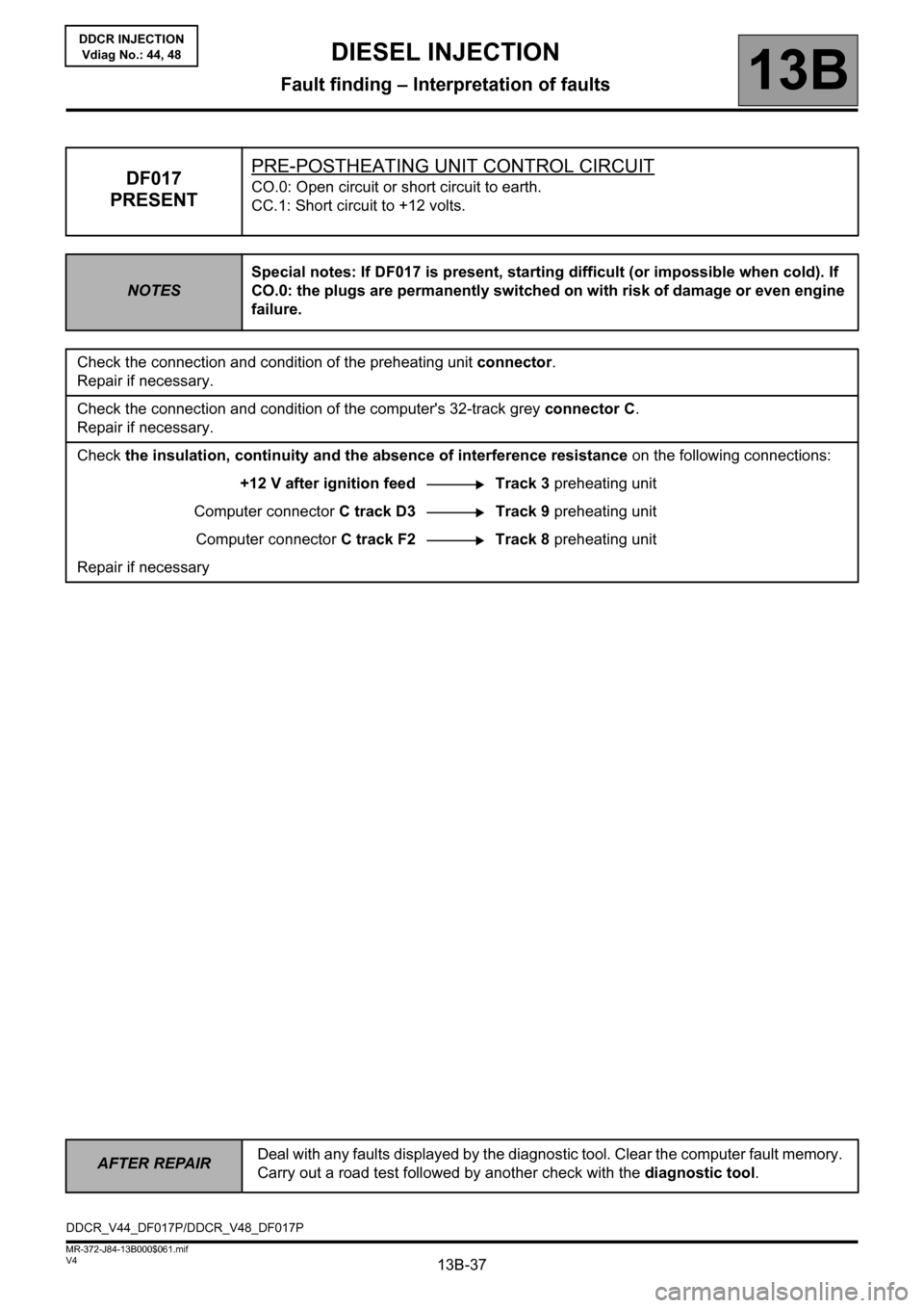
13B-37
AFTER REPAIRDeal with any faults displayed by the diagnostic tool. Clear the computer fault memory.
Carry out a road test followed by another check with the diagnostic tool.
V4 MR-372-J84-13B000$061.mif
DIESEL INJECTION
Fault finding – Interpretation of faults13B
DDCR INJECTION
Vdiag No.: 44, 48
DF017
PRESENTPRE-POSTHEATING UNIT CONTROL CIRCUITCO.0: Open circuit or short circuit to earth.
CC.1: Short circuit to +12 volts.
NOTESSpecial notes: If DF017 is present, starting difficult (or impossible when cold). If
CO.0: the plugs are permanently switched on with risk of damage or even engine
failure.
Check the connection and condition of the preheating unit connector.
Repair if necessary.
Check the connection and condition of the computer's 32-track grey connector C.
Repair if necessary.
Check the insulation, continuity and the absence of interference resistance on the following connections:
+12 V after ignition feed Track 3 preheating unit
Computer connector C track D3 Track 9 preheating unit
Computer connector C track F2 Track 8 preheating unit
Repair if necessary
DDCR_V44_DF017P/DDCR_V48_DF017P
Page 38 of 198
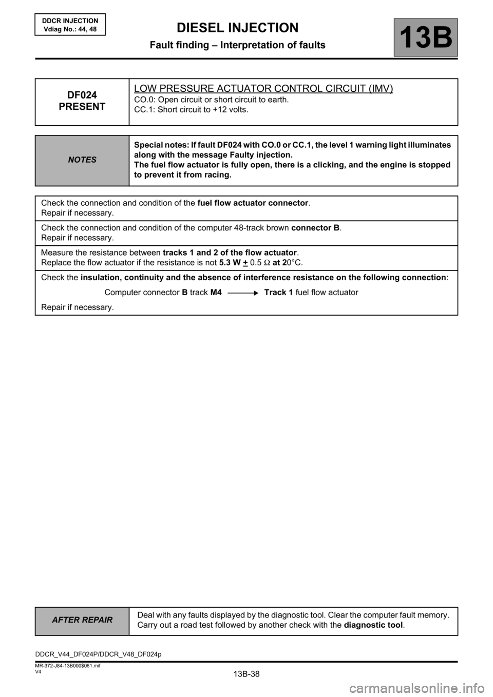
13B-38
AFTER REPAIRDeal with any faults displayed by the diagnostic tool. Clear the computer fault memory.
Carry out a road test followed by another check with the diagnostic tool.
V4 MR-372-J84-13B000$061.mif
DIESEL INJECTION
Fault finding – Interpretation of faults13B
DDCR INJECTION
Vdiag No.: 44, 48
DF024
PRESENTLOW PRESSURE ACTUATOR CONTROL CIRCUIT (IMV)CO.0: Open circuit or short circuit to earth.
CC.1: Short circuit to +12 volts.
NOTESSpecial notes: If fault DF024 with CO.0 or CC.1, the level 1 warning light illuminates
along with the message Faulty injection.
The fuel flow actuator is fully open, there is a clicking, and the engine is stopped
to prevent it from racing.
Check the connection and condition of the fuel flow actuator connector.
Repair if necessary.
Check the connection and condition of the computer 48-track brown connector B.
Repair if necessary.
Measure the resistance between tracks 1 and 2 of the flow actuator.
Replace the flow actuator if the resistance is not 5.3 W +
0.5 Ω at 20°C.
Check the insulation, continuity and the absence of interference resistance on the following connection:
Computer connector B track M4 Track 1 fuel flow actuator
Repair if necessary.
DDCR_V44_DF024P/DDCR_V48_DF024p
Page 39 of 198
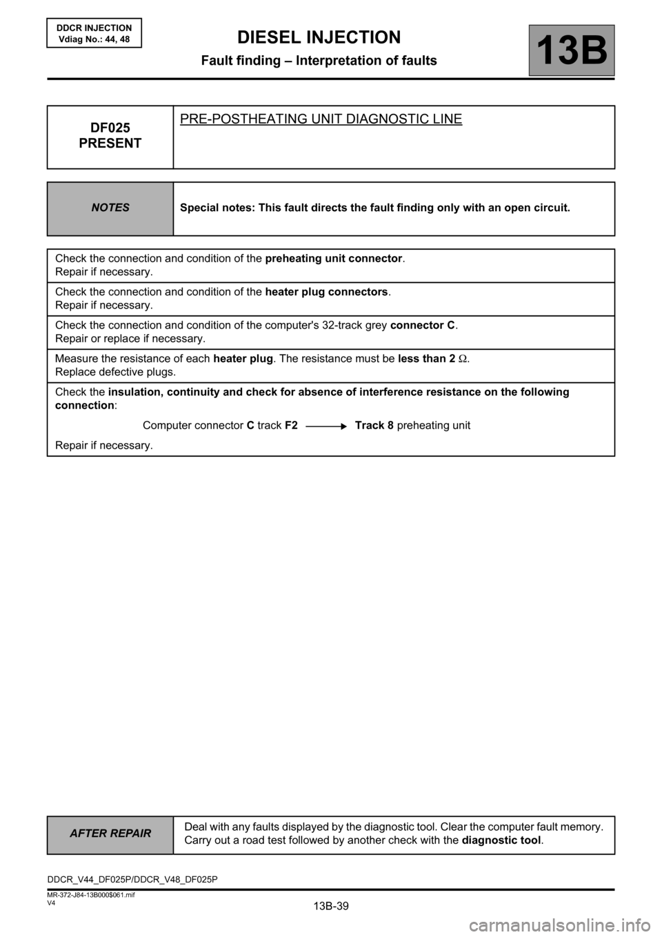
13B-39
AFTER REPAIRDeal with any faults displayed by the diagnostic tool. Clear the computer fault memory.
Carry out a road test followed by another check with the diagnostic tool.
V4 MR-372-J84-13B000$061.mif
DIESEL INJECTION
Fault finding – Interpretation of faults13B
DDCR INJECTION
Vdiag No.: 44, 48
DF025
PRESENTPRE-POSTHEATING UNIT DIAGNOSTIC LINE
NOTESSpecial notes: This fault directs the fault finding only with an open circuit.
Check the connection and condition of the preheating unit connector.
Repair if necessary.
Check the connection and condition of the heater plug connectors.
Repair if necessary.
Check the connection and condition of the computer's 32-track grey connector C.
Repair or replace if necessary.
Measure the resistance of each heater plug. The resistance must be less than 2 Ω.
Replace defective plugs.
Check the insulation, continuity and check for absence of interference resistance on the following
connection:
Computer connector C track F2 Track 8 preheating unit
Repair if necessary.
DDCR_V44_DF025P/DDCR_V48_DF025P
Page 41 of 198
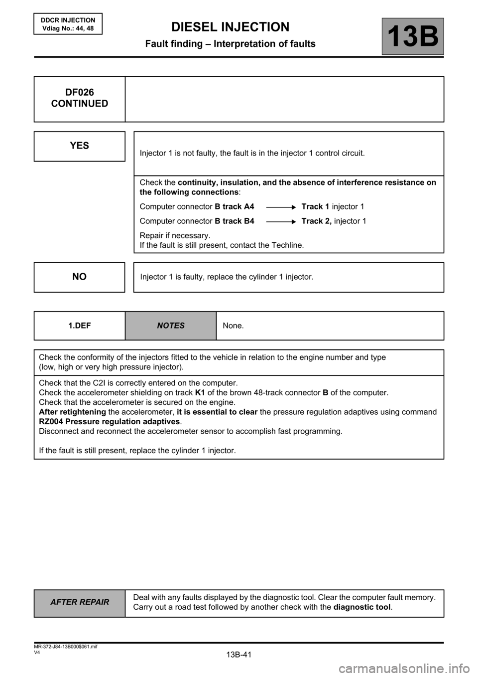
13B-41
AFTER REPAIRDeal with any faults displayed by the diagnostic tool. Clear the computer fault memory.
Carry out a road test followed by another check with the diagnostic tool.
V4 MR-372-J84-13B000$061.mif
DIESEL INJECTION
Fault finding – Interpretation of faults13B
DDCR INJECTION
Vdiag No.: 44, 48
DF026
CONTINUED
YES
Injector 1 is not faulty, the fault is in the injector 1 control circuit.
Check the continuity, insulation, and the absence of interference resistance on
the following connections:
Computer connector B track A4 Track 1 injector 1
Computer connector B track B4 Track 2, injector 1
Repair if necessary.
If the fault is still present, contact the Techline.
NOInjector 1 is faulty, replace the cylinder 1 injector.
1.DEF
NOTESNone.
Check the conformity of the injectors fitted to the vehicle in relation to the engine number and type
(low, high or very high pressure injector).
Check that the C2I is correctly entered on the computer.
Check the accelerometer shielding on track K1 of the brown 48-track connector B of the computer.
Check that the accelerometer is secured on the engine.
After retightening the accelerometer, it is essential to clear the pressure regulation adaptives using command
RZ004 Pressure regulation adaptives.
Disconnect and reconnect the accelerometer sensor to accomplish fast programming.
If the fault is still present, replace the cylinder 1 injector.
Page 43 of 198
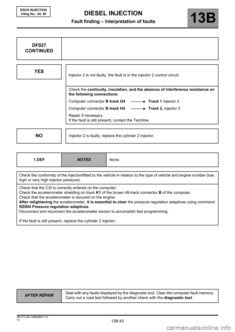
13B-43
AFTER REPAIRDeal with any faults displayed by the diagnostic tool. Clear the computer fault memory.
Carry out a road test followed by another check with the diagnostic tool.
V4 MR-372-J84-13B000$061.mif
DIESEL INJECTION
Fault finding – Interpretation of faults13B
DDCR INJECTION
Vdiag No.: 44, 48
DF027
CONTINUED
YES
Injector 2 is not faulty, the fault is in the injector 2 control circuit.
Check the continuity, insulation, and the absence of interference resistance on
the following connections:
Computer connector B track G4 Track 1 injector 2
Computer connector B track H4 Track 2, injector 2
Repair if necessary.
If the fault is still present, contact the Techline.
NOInjector 2 is faulty, replace the cylinder 2 injector.
1.DEF
NOTESNone.
Check the conformity of the injectorsfitted to the vehicle in relation to the type of vehicle and engine number (low,
high or very high injector pressure).
Check that the C2I is correctly entered on the computer.
Check the accelerometer shielding on track K1 of the brown 48-track connector B of the computer.
Check that the accelerometer is secured on the engine.
After retightening the accelerometer, it is essential to clear the pressure regulation adaptives using command
RZ004 Pressure regulation adaptives.
Disconnect and reconnect the accelerometer sensor to accomplish fast programming.
If the fault is still present, replace the cylinder 2 injector.
Page 45 of 198
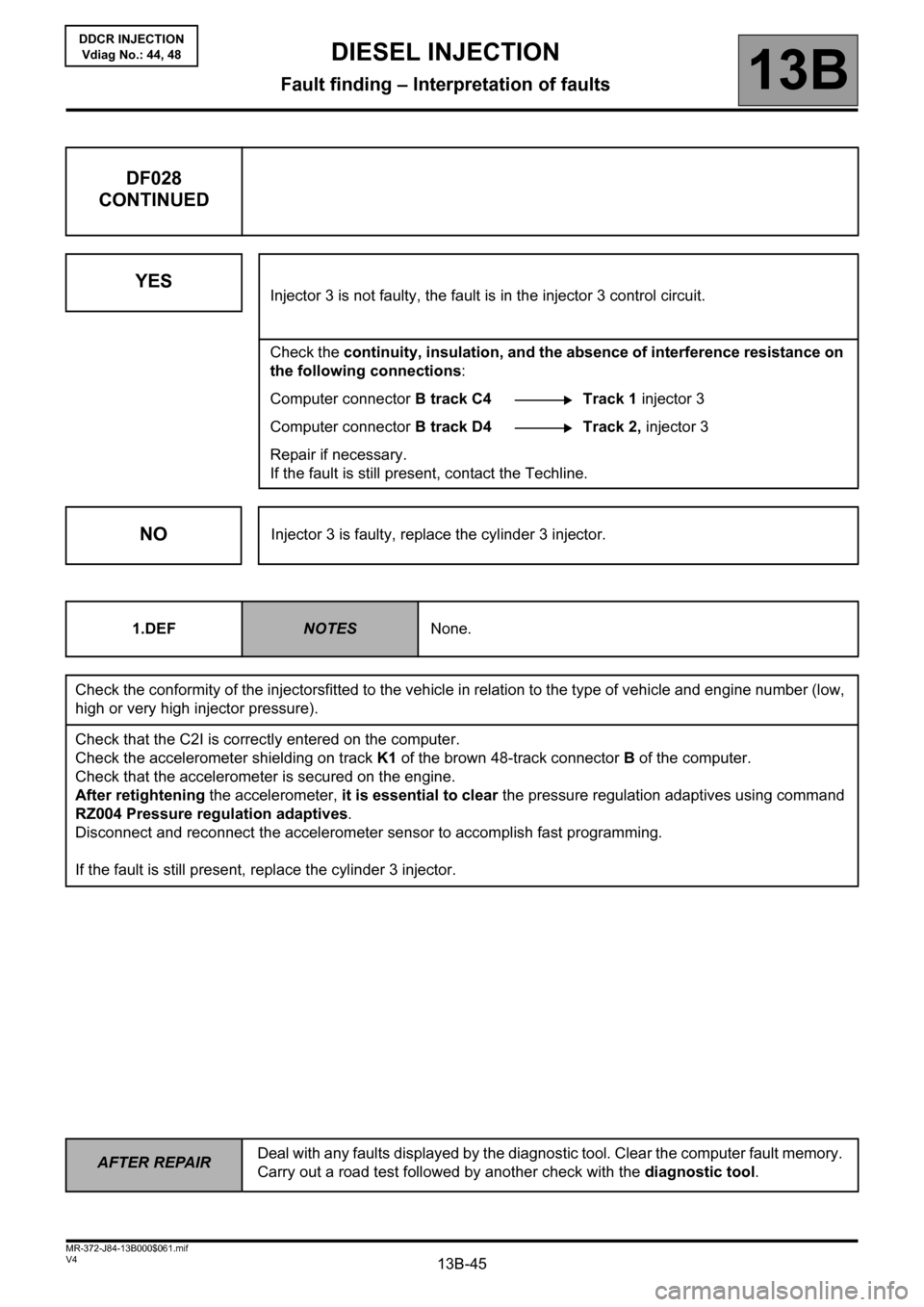
13B-45
AFTER REPAIRDeal with any faults displayed by the diagnostic tool. Clear the computer fault memory.
Carry out a road test followed by another check with the diagnostic tool.
V4 MR-372-J84-13B000$061.mif
DIESEL INJECTION
Fault finding – Interpretation of faults13B
DDCR INJECTION
Vdiag No.: 44, 48
DF028
CONTINUED
YES
Injector 3 is not faulty, the fault is in the injector 3 control circuit.
Check the continuity, insulation, and the absence of interference resistance on
the following connections:
Computer connector B track C4 Track 1 injector 3
Computer connector B track D4 Track 2, injector 3
Repair if necessary.
If the fault is still present, contact the Techline.
NOInjector 3 is faulty, replace the cylinder 3 injector.
1.DEF
NOTESNone.
Check the conformity of the injectorsfitted to the vehicle in relation to the type of vehicle and engine number (low,
high or very high injector pressure).
Check that the C2I is correctly entered on the computer.
Check the accelerometer shielding on track K1 of the brown 48-track connector B of the computer.
Check that the accelerometer is secured on the engine.
After retightening the accelerometer, it is essential to clear the pressure regulation adaptives using command
RZ004 Pressure regulation adaptives.
Disconnect and reconnect the accelerometer sensor to accomplish fast programming.
If the fault is still present, replace the cylinder 3 injector.
Page 47 of 198
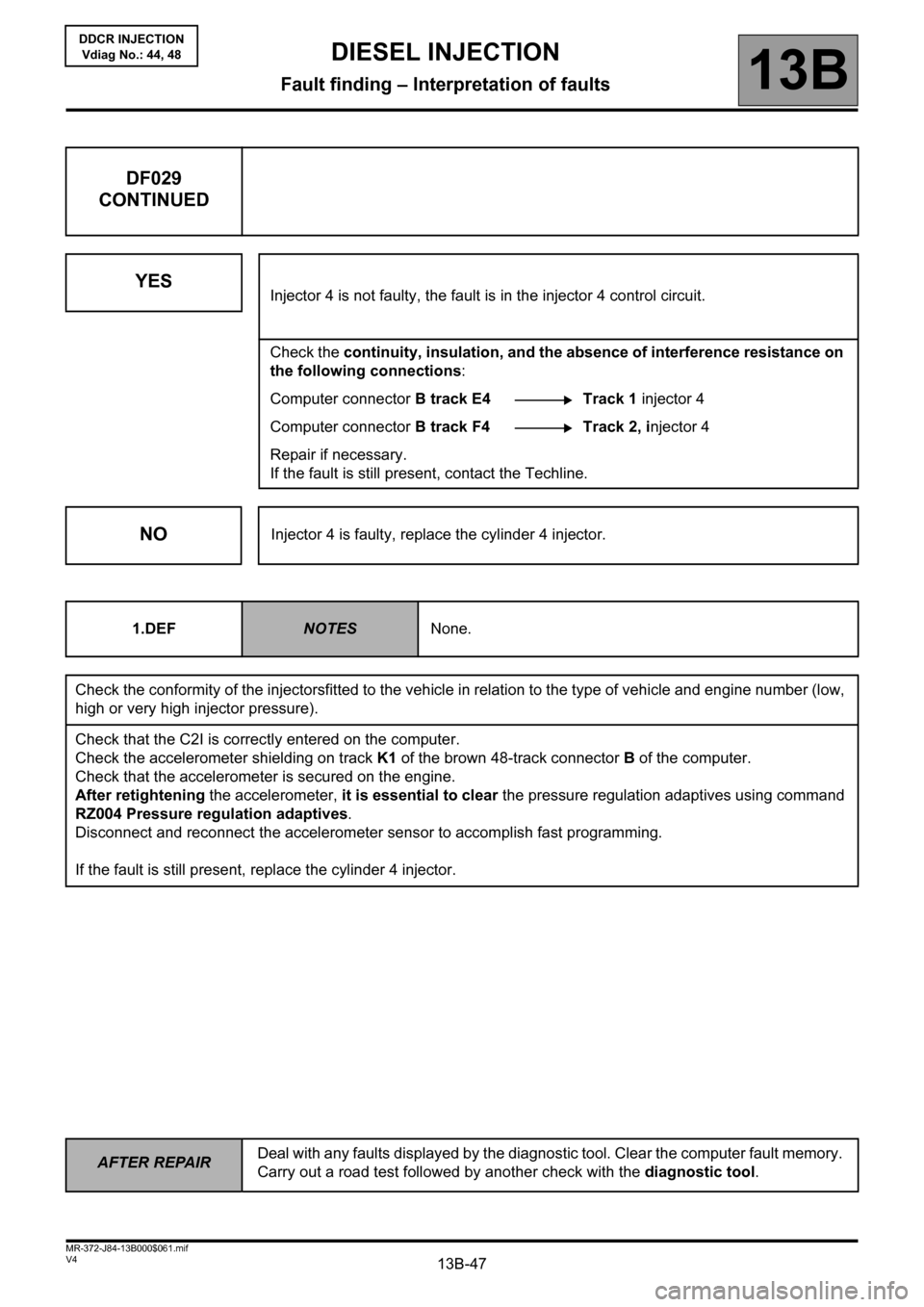
13B-47
AFTER REPAIRDeal with any faults displayed by the diagnostic tool. Clear the computer fault memory.
Carry out a road test followed by another check with the diagnostic tool.
V4 MR-372-J84-13B000$061.mif
DIESEL INJECTION
Fault finding – Interpretation of faults13B
DDCR INJECTION
Vdiag No.: 44, 48
DF029
CONTINUED
YES
Injector 4 is not faulty, the fault is in the injector 4 control circuit.
Check the continuity, insulation, and the absence of interference resistance on
the following connections:
Computer connector B track E4 Track 1 injector 4
Computer connector B track F4 Track 2, injector 4
Repair if necessary.
If the fault is still present, contact the Techline.
NOInjector 4 is faulty, replace the cylinder 4 injector.
1.DEF
NOTESNone.
Check the conformity of the injectorsfitted to the vehicle in relation to the type of vehicle and engine number (low,
high or very high injector pressure).
Check that the C2I is correctly entered on the computer.
Check the accelerometer shielding on track K1 of the brown 48-track connector B of the computer.
Check that the accelerometer is secured on the engine.
After retightening the accelerometer, it is essential to clear the pressure regulation adaptives using command
RZ004 Pressure regulation adaptives.
Disconnect and reconnect the accelerometer sensor to accomplish fast programming.
If the fault is still present, replace the cylinder 4 injector.
Page 49 of 198
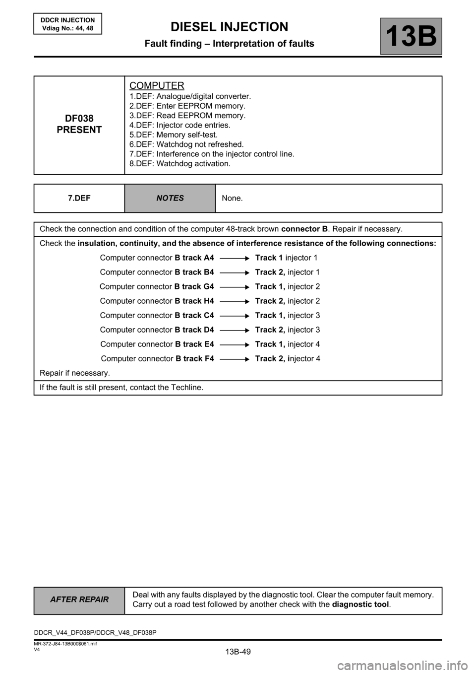
13B-49
AFTER REPAIRDeal with any faults displayed by the diagnostic tool. Clear the computer fault memory.
Carry out a road test followed by another check with the diagnostic tool.
V4 MR-372-J84-13B000$061.mif
DIESEL INJECTION
Fault finding – Interpretation of faults13B
DDCR INJECTION
Vdiag No.: 44, 48
DF038
PRESENTCOMPUTER
1.DEF: Analogue/digital converter.
2.DEF: Enter EEPROM memory.
3.DEF: Read EEPROM memory.
4.DEF: Injector code entries.
5.DEF: Memory self-test.
6.DEF: Watchdog not refreshed.
7.DEF: Interference on the injector control line.
8.DEF: Watchdog activation.
7.DEF
NOTESNone.
Check the connection and condition of the computer 48-track brown connector B. Repair if necessary.
Check the insulation, continuity, and the absence of interference resistance of the following connections:
Computer connector B track A4 Track 1 injector 1
Computer connector B track B4 Track 2, injector 1
Computer connector B track G4 Track 1, injector 2
Computer connector B track H4 Track 2, injector 2
Computer connector B track C4 Track 1, injector 3
Computer connector B track D4 Track 2, injector 3
Computer connector B track E4 Track 1, injector 4
Computer connector B track F4 Track 2, injector 4
Repair if necessary.
If the fault is still present, contact the Techline.
DDCR_V44_DF038P/DDCR_V48_DF038P
Page 51 of 198
13B-51
AFTER REPAIRDeal with any faults displayed by the diagnostic tool. Clear the computer fault memory.
Carry out a road test followed by another check with the diagnostic tool.
V4 MR-372-J84-13B000$061.mif
DIESEL INJECTION
Fault finding – Interpretation of faults13B
DDCR INJECTION
Vdiag No.: 44, 48
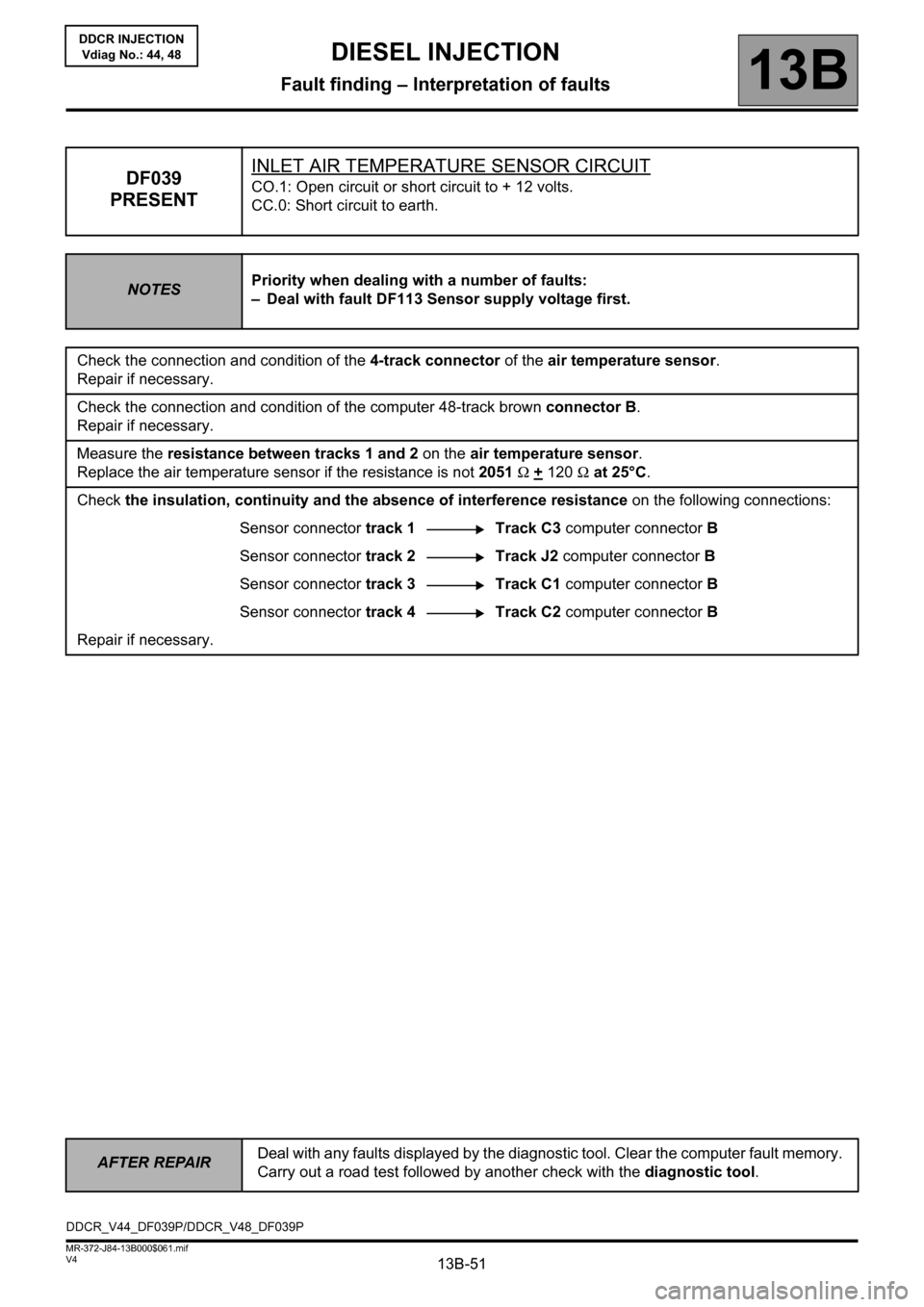
DF039
PRESENTINLET AIR TEMPERATURE SENSOR CIRCUITCO.1: Open circuit or short circuit to + 12 volts.
CC.0: Short circuit to earth.
NOTESPriority when dealing with a number of faults:
– Deal with fault DF113 Sensor supply voltage first.
Check the connection and condition of the 4-track connector of the air temperature sensor.
Repair if necessary.
Check the connection and condition of the computer 48-track brown connector B.
Repair if necessary.
Measure the resistance between tracks 1 and 2 on the air temperature sensor.
Replace the air temperature sensor if the resistance is not 2051 Ω +
120 Ω at 25°C.
Check the insulation, continuity and the absence of interference resistance on the following connections:
Sensor connector track 1 Track C3 computer connector B
Sensor connector track 2 Track J2 computer connector B
Sensor connector track 3 Track C1 computer connector B
Sensor connector track 4 Track C2 computer connector B
Repair if necessary.
DDCR_V44_DF039P/DDCR_V48_DF039P
Page 52 of 198
13B-52
AFTER REPAIRDeal with any faults displayed by the diagnostic tool. Clear the computer fault memory.
Carry out a road test followed by another check with the diagnostic tool.
V4 MR-372-J84-13B000$061.mif
DIESEL INJECTION
Fault finding – Interpretation of faults13B
DDCR INJECTION
Vdiag No.: 44, 48
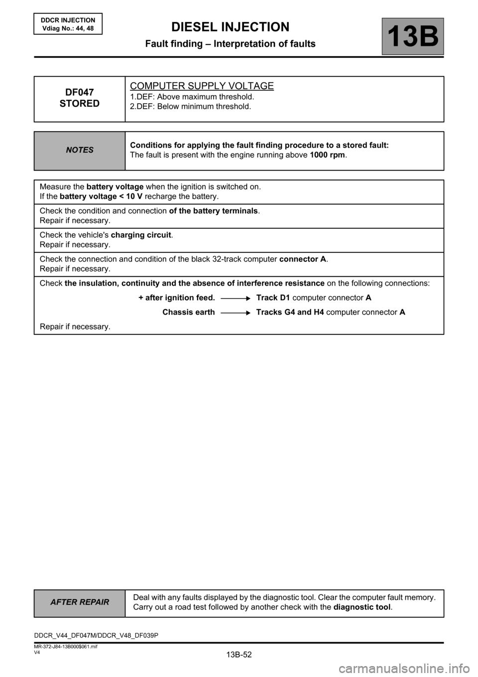
DF047
STOREDCOMPUTER SUPPLY VOLTAGE1.DEF: Above maximum threshold.
2.DEF: Below minimum threshold.
NOTESConditions for applying the fault finding procedure to a stored fault:
The fault is present with the engine running above 1000 rpm.
Measure the battery voltage when the ignition is switched on.
If the battery voltage < 10 V recharge the battery.
Check the condition and connection of the battery terminals.
Repair if necessary.
Check the vehicle's charging circuit.
Repair if necessary.
Check the connection and condition of the black 32-track computer connector A.
Repair if necessary.
Check the insulation, continuity and the absence of interference resistance on the following connections:
+ after ignition feed. Track D1 computer connector A
Chassis earth Tracks G4 and H4 computer connector A
Repair if necessary.
DDCR_V44_DF047M/DDCR_V48_DF039P