start RENAULT SCENIC 2011 J95 / 3.G Engine And Peripherals Owner's Manual
[x] Cancel search | Manufacturer: RENAULT, Model Year: 2011, Model line: SCENIC, Model: RENAULT SCENIC 2011 J95 / 3.GPages: 198, PDF Size: 0.85 MB
Page 93 of 198
13B-93V4 MR-372-J84-13B000$070.mif
DIESEL INJECTION
Fault finding – Conformity check13B
DDCR INJECTION
Vdiag No.: 44, 48
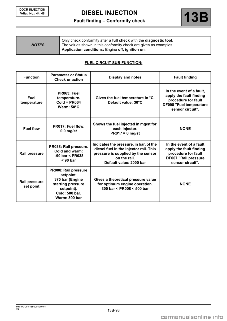
FUEL CIRCUIT SUB-FUNCTION:
NOTESOnly check conformity after a full check with the diagnostic tool.
The values shown in this conformity check are given as examples.
Application conditions: Engine off, ignition on.
FunctionParameter or Status
Check or actionDisplay and notes Fault finding
Fuel
temperaturePR063: Fuel
temperature.
Cold = PR064
Warm: 50°CGives the fuel temperature in °C.
Default value: 30°CIn the event of a fault,
apply the fault finding
procedure for fault
DF098 "Fuel temperature
sensor circuit".
Fuel flowPR017: Fuel flow.
0.0 mg/stShows the fuel injected in mg/st for
each injector.
PR017 = 0 mg/stNONE
Rail pressurePR038: Rail pressure.
Cold and warm:
-90 bar < PR038
<90barIndicates the pressure, in bar, of the
diesel fuel in the injector rail. This
pressure is supplied by the sensor
on the rail.
Default value: 2000 barIn the event of a fault
apply the fault finding
procedure for fault
DF007 "Rail pressure
sensor circuit".
Rail pressure
set pointPR008: Rail pressure
setpoint.
375 bar (Engine
starting pressure
setpoint).
Cold: 500 bar.
Warm: 300 barGives a theoretical pressure value
for optimum engine operation.
300 bar < PR008 < 500 barNONE
Page 105 of 198
13B-105V4 MR-372-J84-13B000$070.mif
DIESEL INJECTION
Fault finding – Conformity check13B
DDCR INJECTION
Vdiag No.: 44, 48
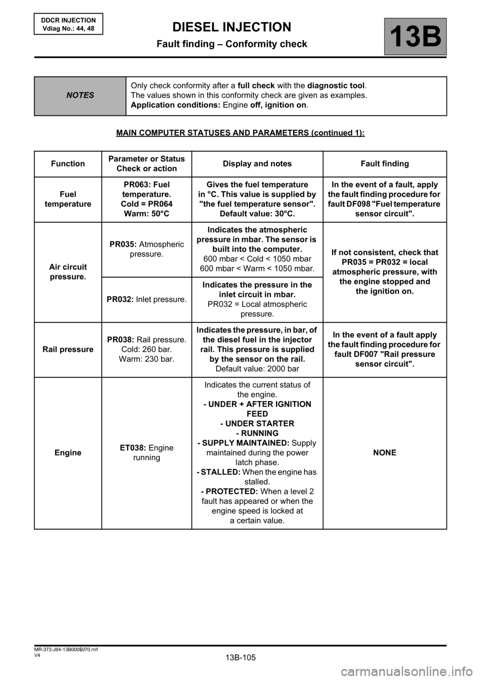
MAIN COMPUTER STATUSES AND PARAMETERS (continued 1):
NOTESOnly check conformity after a full check with the diagnostic tool.
The values shown in this conformity check are given as examples.
Application conditions: Engine off, ignition on.
FunctionParameter or Status
Check or actionDisplay and notes Fault finding
Fuel
temperaturePR063: Fuel
temperature.
Cold = PR064
Warm: 50°CGives the fuel temperature
in °C. This value is supplied by
"the fuel temperature sensor".
Default value: 30°C.In the event of a fault, apply
the fault finding procedure for
fault DF098 "Fuel temperature
sensor circuit".
Air circuit
pressure.PR035: Atmospheric
pressure.Indicates the atmospheric
pressure in mbar. The sensor is
built into the computer.
600 mbar < Cold < 1050 mbar
600 mbar < Warm < 1050 mbar.If not consistent, check that
PR035 = PR032 = local
atmospheric pressure, with
the engine stopped and
the ignition on.
PR032: Inlet pressure.Indicates the pressure in the
inlet circuit in mbar.
PR032 = Local atmospheric
pressure.
Rail pressurePR038: Rail pressure.
Cold: 260 bar.
Warm: 230 bar.Indicates the pressure, in bar, of
the diesel fuel in the injector
rail. This pressure is supplied
by the sensor on the rail.
Default value: 2000 barIn the event of a fault apply
the fault finding procedure for
fault DF007 "Rail pressure
sensor circuit".
EngineET038: Engine
runningIndicates the current status of
the engine.
- UNDER + AFTER IGNITION
FEED
- UNDER STARTER
- RUNNING
- SUPPLY MAINTAINED: Supply
maintained during the power
latch phase.
- STALLED: When the engine has
stalled.
- PROTECTED: When a level 2
fault has appeared or when the
engine speed is locked at
a certain value.NONE
Page 107 of 198
13B-107V4 MR-372-J84-13B000$070.mif
DIESEL INJECTION
Fault finding – Conformity check13B
DDCR INJECTION
Vdiag No.: 44, 48
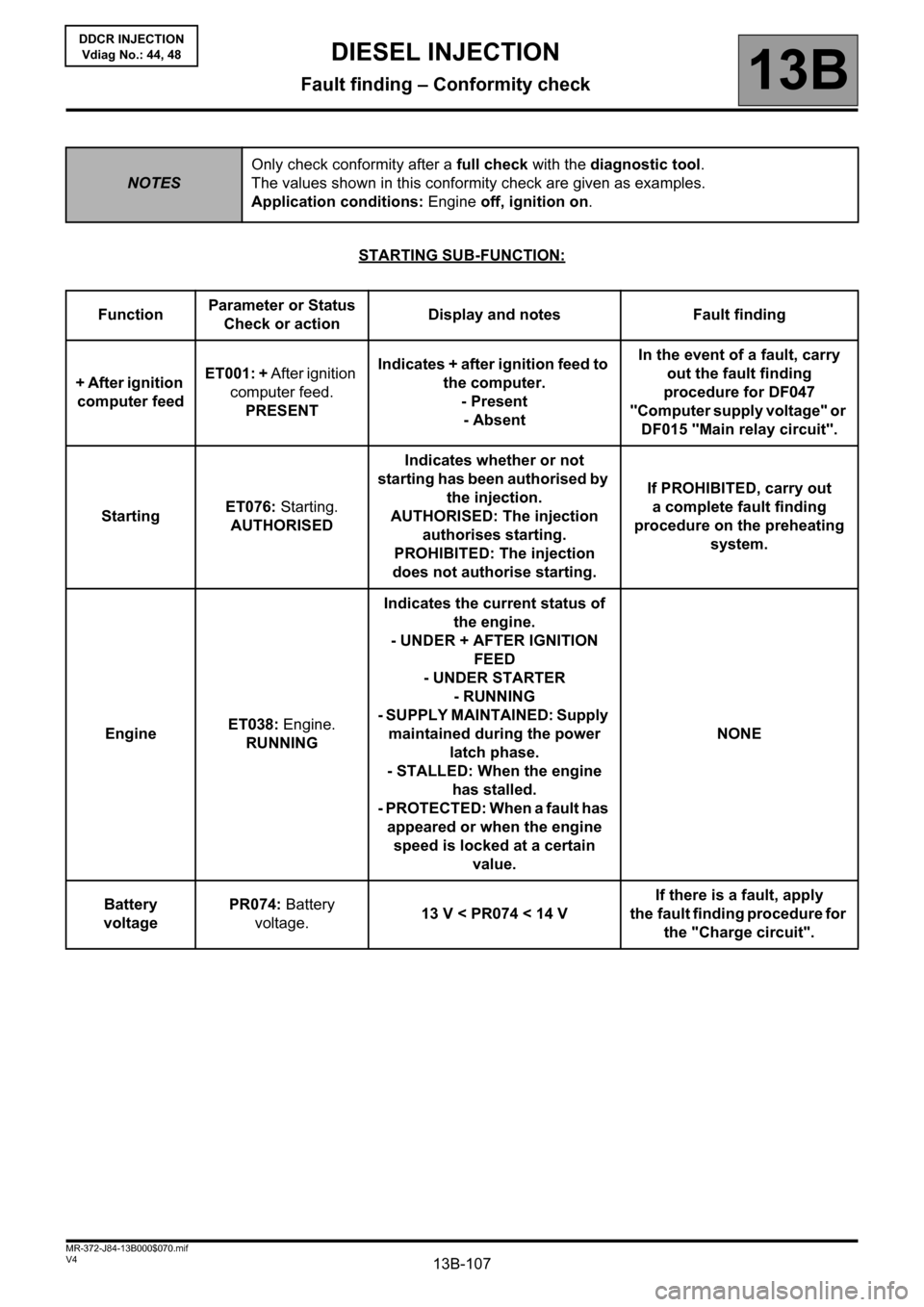
STARTING SUB-FUNCTION:
NOTESOnly check conformity after a full check with the diagnostic tool.
The values shown in this conformity check are given as examples.
Application conditions: Engine off, ignition on.
FunctionParameter or Status
Check or actionDisplay and notes Fault finding
+ After ignition
computer feedET001: + After ignition
computer feed.
PRESENTIndicates + after ignition feed to
the computer.
- Present
- AbsentIn the event of a fault, carry
out the fault finding
procedure for DF047
"Computer supply voltage" or
DF015 "Main relay circuit".
StartingET076: Starting.
AUTHORISEDIndicates whether or not
starting has been authorised by
the injection.
AUTHORISED: The injection
authorises starting.
PROHIBITED: The injection
does not authorise starting.If PROHIBITED, carry out
a complete fault finding
procedure on the preheating
system.
EngineET038: Engine.
RUNNINGIndicates the current status of
the engine.
- UNDER + AFTER IGNITION
FEED
- UNDER STARTER
- RUNNING
- SUPPLY MAINTAINED: Supply
maintained during the power
latch phase.
- STALLED: When the engine
has stalled.
- PROTECTED: When a fault has
appeared or when the engine
speed is locked at a certain
value.NONE
Battery
voltagePR074: Battery
voltage.13 V < PR074 < 14 VIf there is a fault, apply
the fault finding procedure for
the "Charge circuit".
Page 109 of 198
13B-109V4 MR-372-J84-13B000$070.mif
DIESEL INJECTION
Fault finding – Conformity check13B
DDCR INJECTION
Vdiag No.: 44, 48
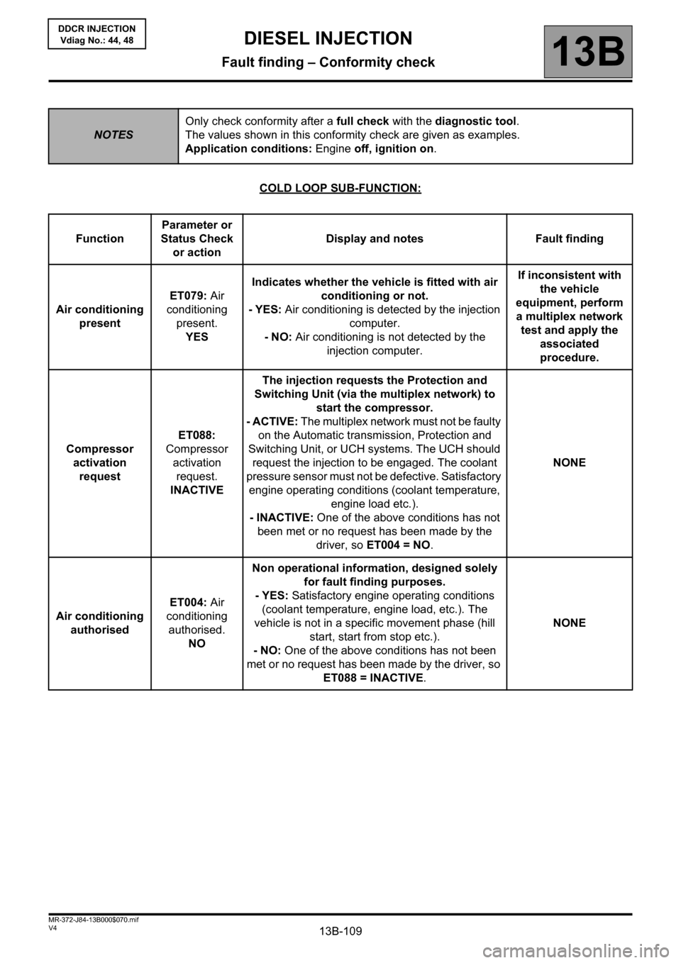
COLD LOOP SUB-FUNCTION:
NOTESOnly check conformity after a full check with the diagnostic tool.
The values shown in this conformity check are given as examples.
Application conditions: Engine off, ignition on.
FunctionParameter or
Status Check
or actionDisplay and notes Fault finding
Air conditioning
presentET079: Air
conditioning
present.
YESIndicates whether the vehicle is fitted with air
conditioning or not.
- YES: Air conditioning is detected by the injection
computer.
- NO: Air conditioning is not detected by the
injection computer.If inconsistent with
the vehicle
equipment, perform
a multiplex network
test and apply the
associated
procedure.
Compressor
activation
requestET088:
Compressor
activation
request.
INACTIVEThe injection requests the Protection and
Switching Unit (via the multiplex network) to
start the compressor.
- ACTIVE: The multiplex network must not be faulty
on the Automatic transmission, Protection and
Switching Unit, or UCH systems. The UCH should
request the injection to be engaged. The coolant
pressure sensor must not be defective. Satisfactory
engine operating conditions (coolant temperature,
engine load etc.).
- INACTIVE: One of the above conditions has not
been met or no request has been made by the
driver, so ET004 = NO.NONE
Air conditioning
authorisedET004: Air
conditioning
authorised.
NONon operational information, designed solely
for fault finding purposes.
- YES: Satisfactory engine operating conditions
(coolant temperature, engine load, etc.). The
vehicle is not in a specific movement phase (hill
start, start from stop etc.).
- NO: One of the above conditions has not been
met or no request has been made by the driver, so
ET088 = INACTIVE.NONE
Page 111 of 198
13B-111V4 MR-372-J84-13B000$070.mif
DIESEL INJECTION
Fault finding – Conformity check13B
DDCR INJECTION
Vdiag No.: 44, 48
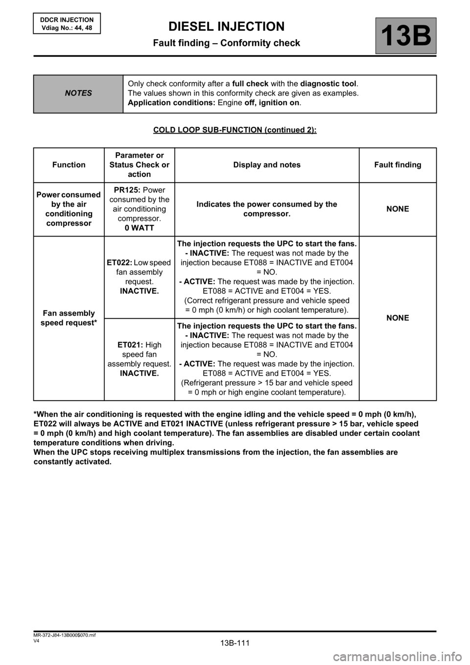
COLD LOOP SUB-FUNCTION (continued 2):
*When the air conditioning is requested with the engine idling and the vehicle speed = 0 mph (0 km/h),
ET022 will always be ACTIVE and ET021 INACTIVE (unless refrigerant pressure > 15 bar, vehicle speed
= 0 mph (0 km/h) and high coolant temperature). The fan assemblies are disabled under certain coolant
temperature conditions when driving.
When the UPC stops receiving multiplex transmissions from the injection, the fan assemblies are
constantly activated.
NOTESOnly check conformity after a full check with the diagnostic tool.
The values shown in this conformity check are given as examples.
Application conditions: Engine off, ignition on.
FunctionParameter or
Status Check or
actionDisplay and notes Fault finding
Power consumed
by the air
conditioning
compressorPR125: Power
consumed by the
air conditioning
compressor.
0 WATTIndicates the power consumed by the
compressor.NONE
Fan assembly
speed request*ET022: Low speed
fan assembly
request.
INACTIVE.The injection requests the UPC to start the fans.
- INACTIVE: The request was not made by the
injection because ET088 = INACTIVE and ET004
=NO.
- ACTIVE: The request was made by the injection.
ET088 = ACTIVE and ET004 = YES.
(Correct refrigerant pressure and vehicle speed
= 0 mph (0 km/h) or high coolant temperature).
NONE
ET021: High
speed fan
assembly request.
INACTIVE.The injection requests the UPC to start the fans.
- INACTIVE: The request was not made by the
injection because ET088 = INACTIVE and ET004
=NO.
- ACTIVE: The request was made by the injection.
ET088 = ACTIVE and ET004 = YES.
(Refrigerant pressure > 15 bar and vehicle speed
= 0 mph or high engine coolant temperature).
Page 113 of 198
13B-113V4 MR-372-J84-13B000$070.mif
DIESEL INJECTION
Fault finding – Conformity check13B
DDCR INJECTION
Vdiag No.: 44, 48
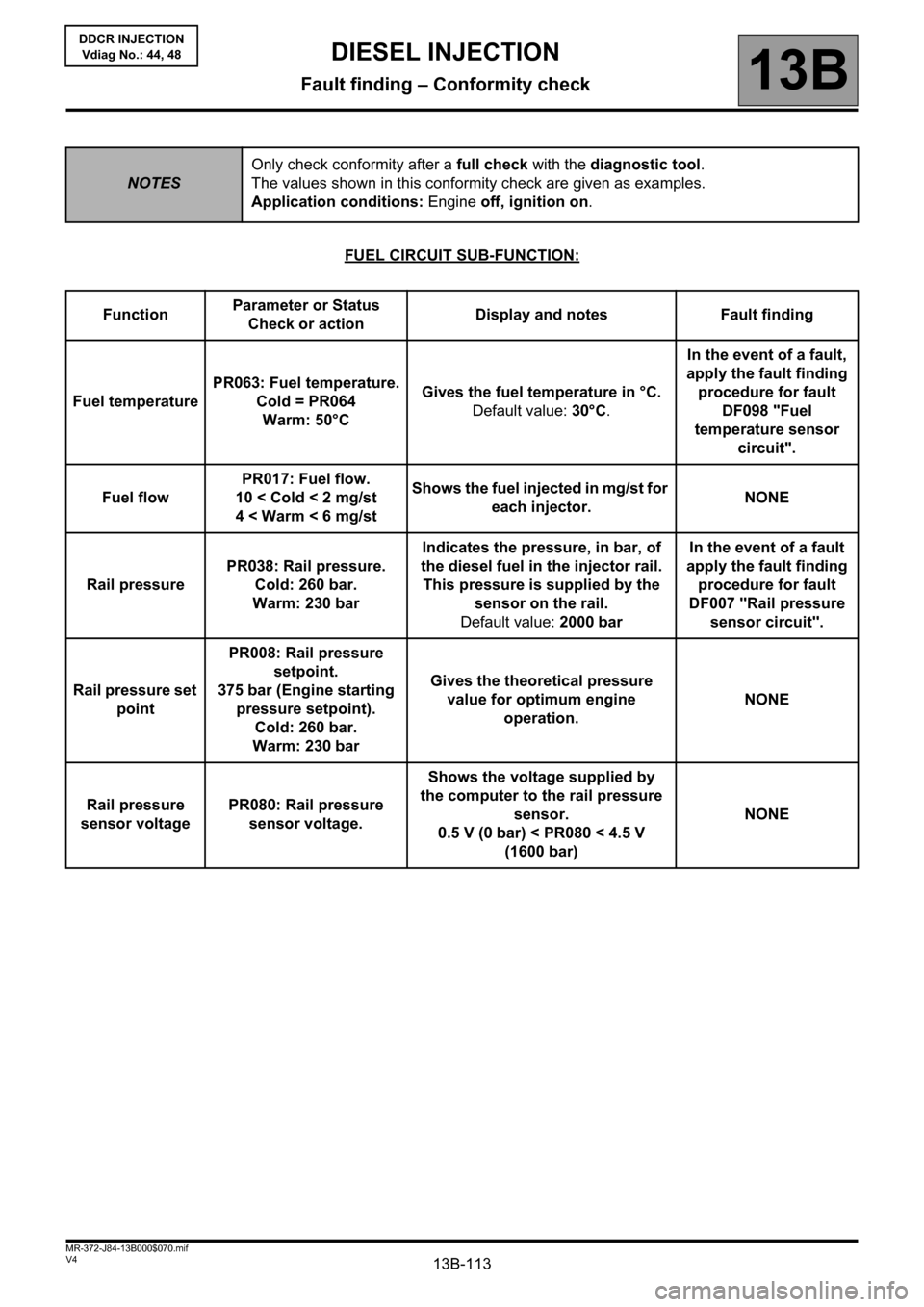
FUEL CIRCUIT SUB-FUNCTION:
NOTESOnly check conformity after a full check with the diagnostic tool.
The values shown in this conformity check are given as examples.
Application conditions: Engine off, ignition on.
FunctionParameter or Status
Check or actionDisplay and notes Fault finding
Fuel temperaturePR063: Fuel temperature.
Cold = PR064
Warm: 50°CGives the fuel temperature in °C.
Default value: 30°C.In the event of a fault,
apply the fault finding
procedure for fault
DF098 "Fuel
temperature sensor
circuit".
Fuel flowPR017: Fuel flow.
10 < Cold < 2 mg/st
4 < Warm < 6 mg/stShows the fuel injected in mg/st for
each injector.NONE
Rail pressurePR038: Rail pressure.
Cold: 260 bar.
Warm: 230 barIndicates the pressure, in bar, of
the diesel fuel in the injector rail.
This pressure is supplied by the
sensor on the rail.
Default value: 2000 barIn the event of a fault
apply the fault finding
procedure for fault
DF007 "Rail pressure
sensor circuit".
Rail pressure set
pointPR008: Rail pressure
setpoint.
375 bar (Engine starting
pressure setpoint).
Cold: 260 bar.
Warm: 230 barGives the theoretical pressure
value for optimum engine
operation.NONE
Rail pressure
sensor voltage PR080: Rail pressure
sensor voltage.Shows the voltage supplied by
the computer to the rail pressure
sensor.
0.5 V (0 bar) < PR080 < 4.5 V
(1600 bar)NONE
Page 124 of 198

13B-124V4 MR-372-J84-13B000$080.mif
13B
DDCR INJECTION
Vdiag No.: 44, 48
* RCH = passenger compartment heating resistor: TOOL STATE DIAGNOSTIC TOOL DESCRIPTION
ET001 + After ignition computer feed
ET003 Engine immobiliser
ET004 Air conditioning authorised.
ET006 Code programmed
ET008 EGR solenoid valve control
ET021 High speed fan assembly request
ET022 Low speed fan assembly request
ET023 Fast idle speed request
ET038 Engine
ET042 Cruise control/speed limiter
ET076 Starting
ET079 Air conditioning present
ET088 Compressor actuation request
ET405 Clutch pedal switch
ET415 Deactivation of cruise control/speed limiter
ET563 Flow capacity function.
ET111 RCH* number set
ET112 RCH* cut-off
ET703 Cruise control/speed limiter button
ET704 Brakecontact No 1
ET705 Brakecontact No 2
DIESEL INJECTION
Fault finding – Status summary table
Page 152 of 198
13B-152V4 MR-372-J84-13B000$120.mif
DIESEL INJECTION
Fault finding – Tests13B
DDCR INJECTION
Vdiag No.: 44, 48
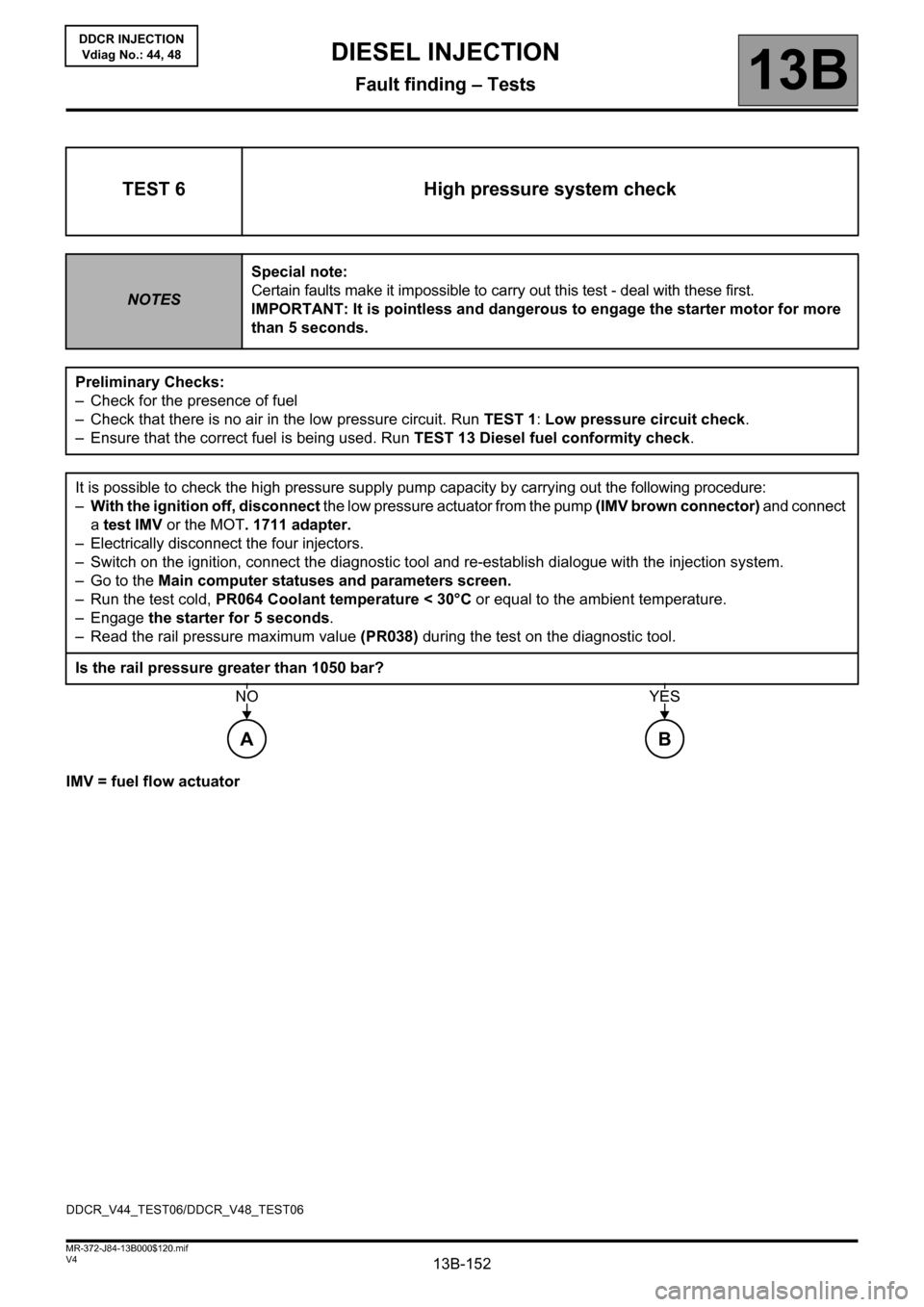
IMV = fuel flow actuator
TEST 6 High pressure system check
NOTESSpecial note:
Certain faults make it impossible to carry out this test - deal with these first.
IMPORTANT: It is pointless and dangerous to engage the starter motor for more
than 5 seconds.
Preliminary Checks:
– Check for the presence of fuel
– Check that there is no air in the low pressure circuit. Run TEST 1: Low pressure circuit check.
– Ensure that the correct fuel is being used. Run TEST 13 Diesel fuel conformity check.
It is possible to check the high pressure supply pump capacity by carrying out the following procedure:
–With the ignition off, disconnect the low pressure actuator from the pump (IMV brown connector) and connect
a test IMV or the MOT. 1711 adapter.
– Electrically disconnect the four injectors.
– Switch on the ignition, connect the diagnostic tool and re-establish dialogue with the injection system.
– Go to the Main computer statuses and parameters screen.
– Run the test cold, PR064 Coolant temperature < 30°C or equal to the ambient temperature.
– Engage the starter for 5 seconds.
– Read the rail pressure maximum value (PR038) during the test on the diagnostic tool.
Is the rail pressure greater than 1050 bar?
A
NO
B
YES
DDCR_V44_TEST06/DDCR_V48_TEST06
Page 155 of 198
13B-155V4 MR-372-J84-13B000$120.mif
DIESEL INJECTION
Fault finding – Tests13B
DDCR INJECTION
Vdiag No.: 44, 48
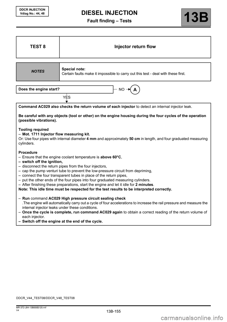
TEST 8 Injector return flow
NOTESSpecial note:
Certain faults make it impossible to carry out this test - deal with these first.
Does the engine start?
Command AC029 also checks the return volume of each injector to detect an internal injector leak.
Be careful with any objects (tool or other) on the engine housing during the four cycles of the operation
(possible vibrations).
Tooling required
–Mot. 1711 Injector flow measuring kit.
Or: Use four pipes with internal diameter 4mm and approximately 50 cm in length, and four graduated measuring
cylinders.
Procedure
– Ensure that the engine coolant temperature is above 60°C,
– switch off the ignition,
– disconnect the return pipes from the four injectors,
– cap the pump venturi tube to prevent the low-pressure circuit from depriming,
– connect the four transparent tubes in place of the return pipes,
– put the other ends of the four pipes into four graduated measuring cylinders.
– After finishing these preparations, start the engine and let it idle for 2 minutes.
Note: This idle time must be respected for the test results to be interpreted correctly.
–Run command AC029 High pressure circuit sealing check
.The engine will automatically carry out a cycle of four accelerations to increase the rail pressure and measure the
internal injector leaks under these conditions.
–Once the cycle is complete, run command AC029 again to obtain a correct reading of the return volume of
each injector.
– Switch off the engine at the end of the cycle.
NOA
YES
DDCR_V44_TEST08/DDCR_V48_TEST08
Page 156 of 198

13B-156V4 MR-372-J84-13B000$120.mif
DIESEL INJECTION
Fault finding – Tests13B
DDCR INJECTION
Vdiag No.: 44, 48
TEST 8
CONTINUED 1
At the end of both cycles, the return volume of each injector should be 35 ml maximum.
If the return volume of one of the injectors is greater than 35 ml, replace the faulty injector (see MR 364 (Mégane
II), MR 370 (Scénic II), Mechanical, 13B, Diesel injection, Diesel injector: Removal - Refitting).
Disconnect the 4 transparent pipes and reconnect the injector return circuit.
Carry out the following test to confirm the repair:
–With the ignition off, disconnect the low pressure actuator from the pump (brown IMV connector) and connect
the test adapter (test IMV, Mot. 1711),
– electrically disconnect the 4 injectors,
– switch on the ignition, connect the diagnostic tool and re-establish dialogue with the injection system,
– Go to the Main computer statuses and parameters screen,
– engage the starter for 5 seconds,
– read the rail pressure maximum value (PR038) on the diagnostic tool during the test.
If the rail pressure (PR038) is less than 1050 bar, run test 6 High pressure system check.
– Switch off the ignition, and reconnect the four injectors electrically,
– disconnect the test filling actuator (test IMV) and reconnect the low pressure actuator connector (IMV) to the
pump
Switch the ignition back on, and clear the injection faults using the diagnostic tool
If the rail pressure (PR038 Rail pressure) is greater than 1050 bar, the repair is correct
End of TEST 8.