sensor RENAULT SCENIC 2014 J95 / 3.G Petrol Injection - Sagem3000 Manual PDF
[x] Cancel search | Manufacturer: RENAULT, Model Year: 2014, Model line: SCENIC, Model: RENAULT SCENIC 2014 J95 / 3.GPages: 181
Page 156 of 181

PETROL INJECTION
Fault finding – Parameter summary table17B
17B - 156V12 MR-372-J84-17B000$630.mif
SAGEM 3000
Program No.: A7
Vdiag No.: 44, 48PETROL INJECTION
Fault finding – Parameter summary table
*OCR: Opening cycle ratioTool parameter Diagnostic tool title
PR001Advance
PR010Idle speed regulation setpoint
PR014Idling speed correction
PR015Engine torque
PR018Estimated air flow
PR028Pedal position (gang 1)
PR029Pedal position (gang 2)
PR030Accelerator pedal position
PR032Inlet pressure
PR035Atmospheric pressure
PR037Refrigerant pressure
PR041Turbocharging pressure
PR055Engine speed
PR058Air temperature
PR064Coolant temperature
PR071Computer feed voltage
PR089Vehicle speed
PR090Idle speed regulation programming value
PR091Theoretical idle speed regulation OCR
PR095Anti-pinking correction
PR096Motorised throttle upper stop programmed value.
PR097Motorised throttle lower stop programmed value.
PR098Upstream oxygen sensor voltage
PR099Downstream oxygen sensor voltage
PR100Torque lapse
PR101Duration of injection
PR102Canister bleed solenoid valve OCR*
JSAA741.0
MR-372-J84-17B000$630.mif
Page 159 of 181
PETROL INJECTION
Fault finding – Interpretation of parameters17B
17B - 159V12 MR-372-J84-17B000$675.mif
SAGEM 3000
Program No.: A7
Vdiag No.: 44, 48
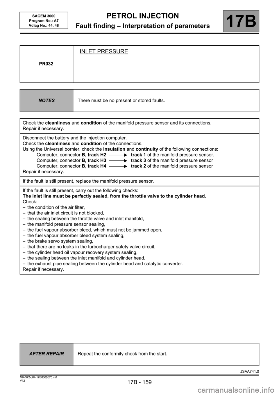
PR032
INLET PRESSURE
NOTESThere must be no present or stored faults.
Check the cleanliness and condition of the manifold pressure sensor and its connections.
Repair if necessary.
Disconnect the battery and the injection computer.
Check the cleanliness and condition of the connections.
Using the Universal bornier, check the insulation and continuity of the following connections:
Computer, connectorB, track H2 track 1 of the manifold pressure sensor.
Computer, connectorB, track H3 track 3 of the manifold pressure sensor
Computer, connectorB, track H4 track 2 of the manifold pressure sensor
Repair if necessary.
If the fault is still present, replace the manifold pressure sensor.
If the fault is still present, carry out the following checks:
The inlet line must be perfectly sealed, from the throttle valve to the cylinder head.
Check:
– the condition of the air filter,
– that the air inlet circuit is not blocked,
– the sealing between the throttle valve and inlet manifold,
– the manifold pressure sensor sealing,
– the fuel vapour absorber bleed, which must not be jammed open,
– the fuel vapour absorber bleed system sealing,
– the brake servo system sealing,
– that there are no leaks in the turbocharger safety valve circuit,
– the cylinder head oil vapour recovery system sealing,
– the sealing between the inlet manifold and cylinder head,
– the exhaust pipe sealing between the cylinder head and catalytic converter.
Repair if necessary.
AFTER REPAIRRepeat the conformity check from the start.
JSAA741.0
Page 160 of 181
PETROL INJECTION
Fault finding – Interpretation of parameters17B
17B - 160V12 MR-372-J84-17B000$675.mif
SAGEM 3000
Program No.: A7
Vdiag No.: 44, 48
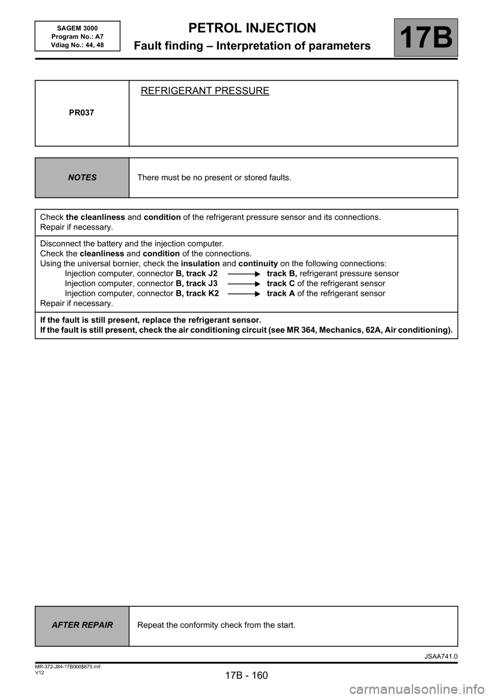
PR037
REFRIGERANT PRESSURE
NOTESThere must be no present or stored faults.
Check the cleanliness and condition of the refrigerant pressure sensor and its connections.
Repair if necessary.
Disconnect the battery and the injection computer.
Check the cleanliness and condition of the connections.
Using the universal bornier, check the insulation and continuity on the following connections:
Injection computer, connectorB, track J2 track B, refrigerant pressure sensor
Injection computer, connectorB, track J3 track C of the refrigerant sensor
Injection computer, connectorB, track K2 track A of the refrigerant sensor
Repair if necessary.
If the fault is still present, replace the refrigerant sensor.
If the fault is still present, check the air conditioning circuit (see MR 364, Mechanics, 62A, Air conditioning).
AFTER REPAIRRepeat the conformity check from the start.
JSAA741.0
Page 162 of 181
PETROL INJECTION
Fault finding – Interpretation of parameters17B
17B - 162V12 MR-372-J84-17B000$675.mif
SAGEM 3000
Program No.: A7
Vdiag No.: 44, 48
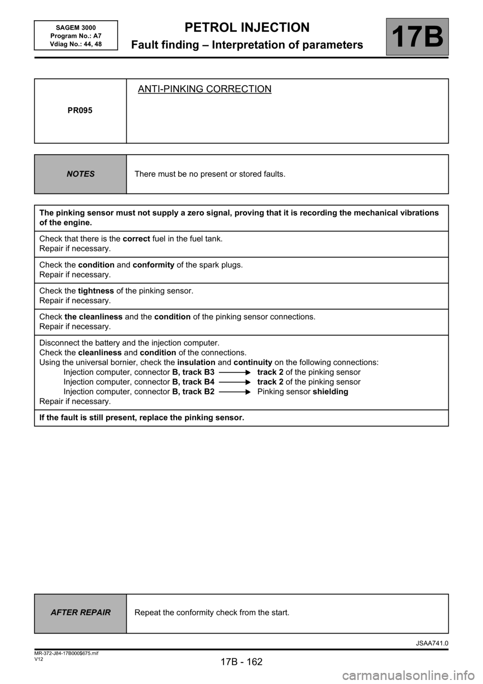
PR095
ANTI-PINKING CORRECTION
NOTESThere must be no present or stored faults.
The pinking sensor must not supply a zero signal, proving that it is recording the mechanical vibrations
of the engine.
Check that there is the correct fuel in the fuel tank.
Repair if necessary.
Check the condition and conformity of the spark plugs.
Repair if necessary.
Check the tightness of the pinking sensor.
Repair if necessary.
Check the cleanliness and the condition of the pinking sensor connections.
Repair if necessary.
Disconnect the battery and the injection computer.
Check the cleanliness and condition of the connections.
Using the universal bornier, check the insulation and continuity on the following connections:
Injection computer, connectorB, track B3 track 2 of the pinking sensor
Injection computer, connectorB, track B4 track 2 of the pinking sensor
Injection computer, connectorB, track B2Pinking sensor shielding
Repair if necessary.
If the fault is still present, replace the pinking sensor.
AFTER REPAIRRepeat the conformity check from the start.
JSAA741.0
Page 163 of 181
PETROL INJECTION
Fault finding – Interpretation of parameters17B
17B - 163V12 MR-372-J84-17B000$675.mif
SAGEM 3000
Program No.: A7
Vdiag No.: 44, 48
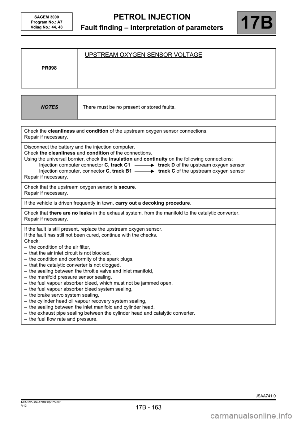
PR098
UPSTREAM OXYGEN SENSOR VOLTAGE
NOTESThere must be no present or stored faults.
Check the cleanliness and condition of the upstream oxygen sensor connections.
Repair if necessary.
Disconnect the battery and the injection computer.
Check the cleanliness and condition of the connections.
Using the universal bornier, check the insulation and continuity on the following connections:
Injection computer connectorC, track C1 track D of the upstream oxygen sensor
Injection computer, connectorC, track B1 track C of the upstream oxygen sensor
Repair if necessary.
Check that the upstream oxygen sensor is secure.
Repair if necessary.
If the vehicle is driven frequently in town, carry out a decoking procedure.
Check that there are no leaks in the exhaust system, from the manifold to the catalytic converter.
Repair if necessary.
If the fault is still present, replace the upstream oxygen sensor.
If the fault has still not been cured, continue with the checks.
Check:
– the condition of the air filter,
– that the air inlet circuit is not blocked,
– the condition and conformity of the spark plugs,
– that the catalytic converter is not clogged,
– the sealing between the throttle valve and inlet manifold,
– the manifold pressure sensor sealing,
– the fuel vapour absorber bleed, which must not be jammed open,
– the fuel vapour absorber bleed system sealing,
– the brake servo system sealing,
– the cylinder head oil vapour recovery system sealing,
– the sealing between the inlet manifold and cylinder head,
– the exhaust pipe sealing between the cylinder head and catalytic converter.
– the fuel flow rate and pressure.
JSAA741.0
Page 165 of 181
PETROL INJECTION
Fault finding – Interpretation of parameters17B
17B - 165V12 MR-372-J84-17B000$675.mif
SAGEM 3000
Program No.: A7
Vdiag No.: 44, 48
PR099
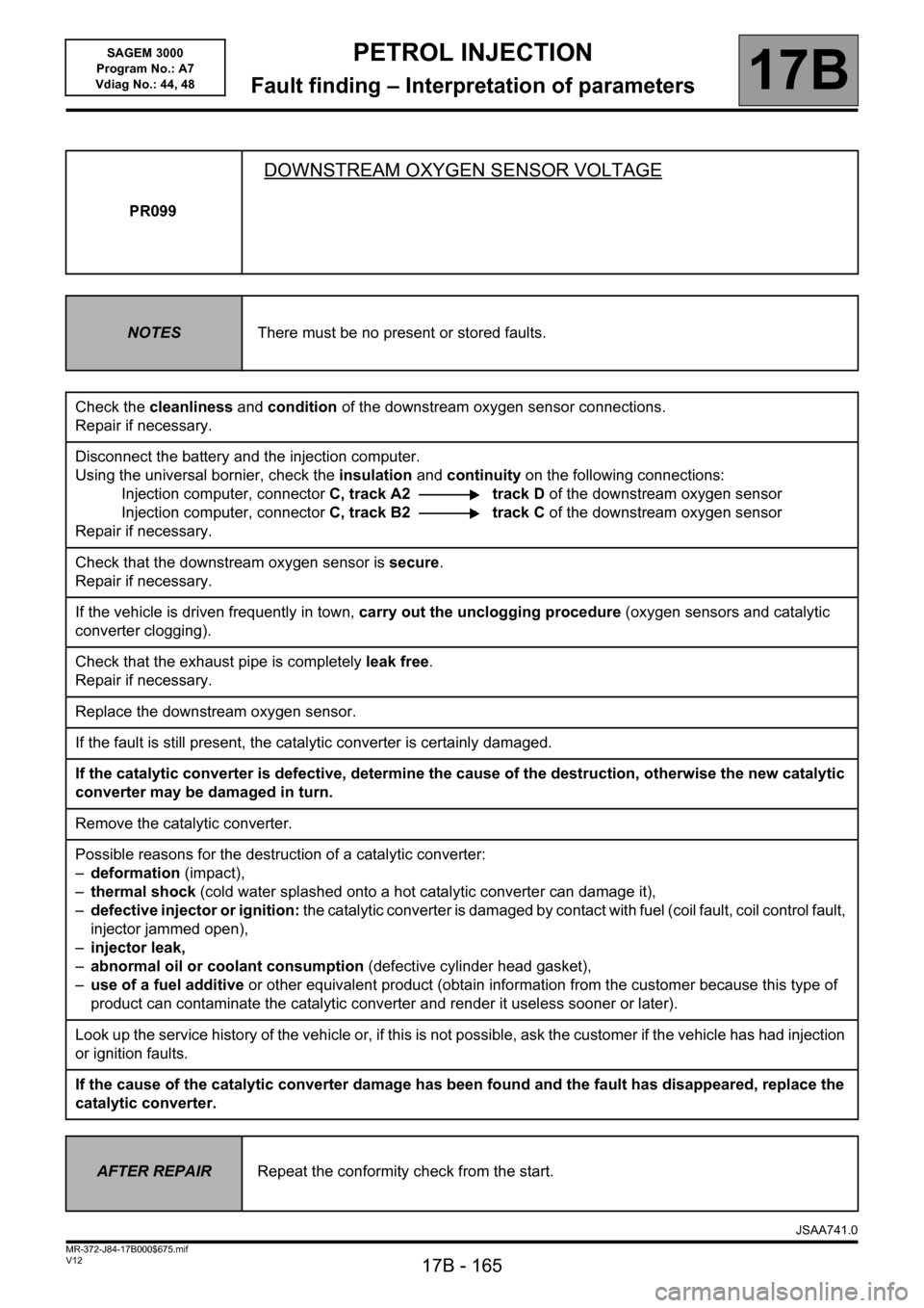
DOWNSTREAM OXYGEN SENSOR VOLTAGE
NOTESThere must be no present or stored faults.
Check the cleanliness and condition of the downstream oxygen sensor connections.
Repair if necessary.
Disconnect the battery and the injection computer.
Using the universal bornier, check the insulation and continuity on the following connections:
Injection computer, connectorC, track A2 track D of the downstream oxygen sensor
Injection computer, connectorC, track B2 track C of the downstream oxygen sensor
Repair if necessary.
Check that the downstream oxygen sensor is secure.
Repair if necessary.
If the vehicle is driven frequently in town, carry out the unclogging procedure (oxygen sensors and catalytic
converter clogging).
Check that the exhaust pipe is completely leak free.
Repair if necessary.
Replace the downstream oxygen sensor.
If the fault is still present, the catalytic converter is certainly damaged.
If the catalytic converter is defective, determine the cause of the destruction, otherwise the new catalytic
converter may be damaged in turn.
Remove the catalytic converter.
Possible reasons for the destruction of a catalytic converter:
–deformation (impact),
–thermal shock (cold water splashed onto a hot catalytic converter can damage it),
–defective injector or ignition: the catalytic converter is damaged by contact with fuel (coil fault, coil control fault,
injector jammed open),
–injector leak,
–abnormal oil or coolant consumption (defective cylinder head gasket),
–use of a fuel additive or other equivalent product (obtain information from the customer because this type of
product can contaminate the catalytic converter and render it useless sooner or later).
Look up the service history of the vehicle or, if this is not possible, ask the customer if the vehicle has had injection
or ignition faults.
If the cause of the catalytic converter damage has been found and the fault has disappeared, replace the
catalytic converter.
AFTER REPAIRRepeat the conformity check from the start.
JSAA741.0
Page 166 of 181

PETROL INJECTION
Fault finding – Command summary table17B
17B - 166V12 MR-372-J84-17B000$720.mif
SAGEM 3000
Program No.: A7
Vdiag No.: 44, 48PETROL INJECTION
Fault finding – Command summary table
Tool commands Diagnostic tool title
SC006Start OBD test: catalytic converter
SC007Start OBD test: O
2 sensors
RZ001Fault memory
RZ005Programming
AC004Turbocharging solenoid valve
AC015Fuel pump relay
AC017Canister bleed solenoid valve
AC018Upstream O
2 sensor heating
AC019Downstream O
2 sensor heating
AC027Motorised throttle
VP008Unlock injector command
VP010Enter VIN
VP013Lock injector command
JSAA741.0
MR-372-J84-17B000$720.mif
Page 168 of 181
17B-168
AFTER REPAIRDeal with any other faults. Clear the fault memory.
Switch off the ignition and perform a road test followed by a check using the diagnostic
tool.
V12 MR-372-J84-17B000$765.mif
PETROL INJECTION
Fault finding – Interpretation of commands17B
SAGEM 3000
Program No.: A7
Vdiag No.: 44, 48
*EOBD: European On Board DiagnosticsSC007
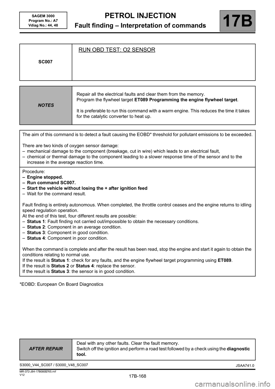
RUN OBD TEST: O2 SENSOR
NOTESRepair all the electrical faults and clear them from the memory.
Program the flywheel target ET089 Programming the engine flywheel target.
It is preferable to run this command with a warm engine. This reduces the time it takes
for the catalytic converter to heat up.
The aim of this command is to detect a fault causing the EOBD* threshold for pollutant emissions to be exceeded.
There are two kinds of oxygen sensor damage:
– mechanical damage to the component (breakage, cut in wire) which leads to an electrical fault,
– chemical or thermal damage to the component leading to a slower response time of the sensor and to the
increase in the average reaction time.
Procedure:
– Engine stopped.
– Run command SC007.
– Start the vehicle without losing the + after ignition feed
– Wait for the command result.
Fault finding is entirely autonomous. When completed, the throttle control ceases and the engine returns to idling
speed regulation operation.
At the end of this test, four different results are possible:
–Status 1: Fault finding not carried out/impossible to obtain the necessary conditions.
–Status 2: Component in an average condition.
–Status 3: Component in good condition.
–Status 4: Component in poor condition.
When the command is complete and after the result has been read, stop the engine and start it again to obtain the
conditions relating to normal use.
If the result is Status 1: check for any faults, and the engine flywheel target programming using ET089.
If the result is Status 2 or Status 4: replace the sensor.
If the result is Status 3: the sensor is in good condition.
S3000_V44_SC007 / S3000_V48_SC007
JSAA741.0
Page 173 of 181
PETROL INJECTION
Fault finding – Help17B
17B - 173V12 MR-372-J84-17B000$810.mif
SAGEM 3000
Program No.: A7
Vdiag No.: 44, 48PETROL INJECTION
Fault finding – Help
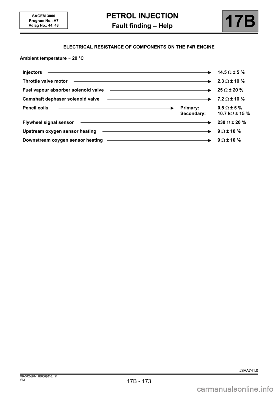
ELECTRICAL RESISTANCE OF COMPONENTS ON THE F4R ENGINE
Ambient temperature ~ 20 °C
Injectors14.5 ±5%
Throttle valve motor2.3 ±10%
Fuel vapour absorber solenoid valve 25 ±20%
Camshaft dephaser solenoid valve 7.2 ±10%
Pencil coils Primary:
Secondary: 0.5 ±5%
10.7 k ±15%
Flywheel signal sensor 230 ±20%
Upstream oxygen sensor heating 9 ±10%
Downstream oxygen sensor heating 9 ±10%
JSAA741.0
MR-372-J84-17B000$810.mif
Page 174 of 181

PETROL INJECTION
Fault finding – Help17B
17B - 174V12 MR-372-J84-17B000$810.mif
SAGEM 3000
Program No.: A7
Vdiag No.: 44, 48
F4R ENGINE
Values for components with variable electrical resistance:
AIR TEMPERATURE SENSOR
DAV IATS 04 - PIE 7700101451 B
Temperature in °C Electrical resistance in
- 40 49930 ± 15 %
- 10 9540 ± 10 %
25 2050 ± 6 %
50 810 ± 6 %
80 309 ± 6 %
110 135 ± 6 %
120 105 ± 6 %
COOLANT TEMPERATURE SENSOR
SYLEA 402114 02 - PIE 7700113867
Temperature in °C Electrical resistance in
- 40 75780 ± 10 %
- 10 12460 ± 10 %
25 2250 ± 5 %
50 810 ± 5 %
80 283 ± 5 %
110 115 ± 5 %
120 88 ± 5 %
JSAA741.0