light RENAULT TWINGO 2009 2.G Chasiss ESP Owner's Manual
[x] Cancel search | Manufacturer: RENAULT, Model Year: 2009, Model line: TWINGO, Model: RENAULT TWINGO 2009 2.GPages: 101
Page 72 of 101
38C-72
AFTER REPAIRClear the computer fault memory.
Carry out a road test followed by another check with the diagnostic tool.
V3 MR-413-X44-38C050$130.mif
38C
Bosch 8.1 ESP
Vdiag No.: 05
ET017BRAKE PEDAL
NOTESSpecial notes:
Only carry out the checks if the PRESSED and RELEASED statuses are inconsistent
with the pedal position.
Use the Wiring Diagram Technical Note for New Twingo.
"Released" STATUS Brake pedal depressed.
If the brake lights are working:
With the connectors of components 1094, 160, intermediate union R107 and component 119 disconnected
(depending on equipment), check the continuity of connection 65A between components 160 and 1094.
If the connection is faulty (see Technical Note 6015A, Electrical wiring repair, Wiring: Precautions for repair),
repair the wiring, otherwise replace it.
If the brake lights are not working:
–Check the condition, fitting and the adjustment of component 160 as well as the conformity of the bulbs.
–Remove (see MR 411, Mechanical, 37A, Mechanical component control, Brake light switch: Removal -
Refitting) and test the operation of component 160:
Continuity between tracks Insulation between tracks
Switch engaged
(Brake pedal released)AP10 and 5A AP10 and 65A
Switch released
(Brake pedal depressed)AP10 and 65A AP10 and 5A
Replace component 160 if necessary.
Check the condition and position of fuse F5 (15A) (see 81C, Fuse box).
Check for +12 V after ignition feed on connection AP10 of component 1016 to the earth MAH.
With intermediate connector R107 and component 160, 1281 and 1081 disconnected (depending on equipment):
–Check the continuity and insulation of connection AP10 between component 1016 and intermediate
connector R107.
–Check the continuity and insulation of connection AP10 between component 160 and intermediate
connector R107.
ESP_V05_ET017
ANTI-LOCK BRAKING SYSTEM
Fault finding – Interpretation of statuses
Page 73 of 101
38C-73
AFTER REPAIRClear the computer fault memory.
Carry out a road test followed by another check with the diagnostic tool.
V3 MR-413-X44-38C050$130.mif
ANTI-LOCK BRAKING SYSTEM
Fault finding – Interpretation of statuses38C
Bosch 8.1 ESP
Vdiag No.: 05
ET017
CONTINUED 1
If the connection is faulty (see Technical Note 6015A, Electrical wiring repair, Wiring: Precautions for repair),
repair the wiring, or replace it.
Connectors of components 645, 172, 173, 639, 1281 and 1094, intermediate connectors R107 and R15 and
connector of component 119 (if present on the vehicle) disconnected from connection 65A:
Check the continuity and insulation of connection 65A between component 160 and intermediate connector
R107.
Check the insulation of connection 65A between component 172 and intermediate connector R107.
Check the insulation of connection 65A between component 173 and intermediate connector R107.
Check the insulation of connection 65A between intermediate connectors R107 and R15.
Check the insulation of connection 65A between component 639 and intermediate connector R15.
Check the insulation of connection 65G between component 645 and intermediate connector R107.
Check the insulation of connection 65G between component 1281 and intermediate connector R107.
If the connection is faulty (see Technical Note 6015A, Electrical wiring repair, Wiring: Precautions for repair),
repair the wiring, otherwise replace it.
If these checks do not reveal any faults:
Carry out a complete check of component 645 using the diagnostic tool.
Perform a visual inspection of components 172, 173, 639 present on connections 65A and AP10 (short circuit
to earth).
Replace the component(s) if necessary:
See MR 411 Mechanical, Rear lighting, Rear wing lights, Removal - Refitting for components 172 and 173.
See MR 411 Mechanical, Rear lighting, High level brake light, Removal - Refitting for component 639.
Page 74 of 101
38C-74
AFTER REPAIRClear the computer fault memory.
Carry out a road test followed by another check with the diagnostic tool.
V3 MR-413-X44-38C050$130.mif
ANTI-LOCK BRAKING SYSTEM
Fault finding – Interpretation of statuses38C
Bosch 8.1 ESP
Vdiag No.: 05
ET017
CONTINUED 2
STATUS "DEPRESSED": Brake pedal released.
–Check the condition, fitting and adjustment of component 160 as well as the conformity of the bulbs.
–Remove (see MR 411, Mechanical, 37A, Mechanical component control, Brake light switch: Removal -
Refitting) and test the operation of component 160:
Continuity between tracks Insulation between tracks
Switch engaged
(Brake pedal released)AP10 and 5A AP10 and 65A
Switch released
(Brake pedal depressed)AP10 and 65A AP10 and 5A
Replace component 160 if necessary.
Connectors of components 645, 172, 173, 639 and 1094, intermediate connectors R107 and R15 and connector
of component 119 (if present on the vehicle) disconnected from connection 65A:
Check the insulation of connection 65A between component 160 and intermediate connector R107.
Check the insulation of connection 65A between component 172 and intermediate connector R107.
Check the insulation of connection 65A between component 173 and intermediate connector R107.
Check the insulation of connection 65A between intermediate connectors R107 and R15.
Check the insulation of connection 65A between component 639 and intermediate connector R15.
Check the insulation of connection 65A between component 645 and intermediate connector R107.
If the connection is faulty (see Technical Note 6015A, Electrical wiring repair, Wiring: Precautions for repair),
repair the wiring, otherwise replace it.
If these checks do not reveal any faults:
Perform a complete check of component 645 using the diagnostic tool.
Perform a visual inspection of components 172, 173, 639 present on connections 65A and AP10 (short circuit to
earth).
Replace the component(s) if necessary:
See MR 411 Mechanical, Rear lighting, Rear wing lights, Removal - Refitting for components 172 and 173.
See MR 411 Mechanical, Rear lighting, High level brake light, Removal - Refitting for component 639.
Page 78 of 101
38C-78
AFTER REPAIRClear the computer fault memory.
Carry out a road test followed by another check with the diagnostic tool.
V3 MR-413-X44-38C050$150.mif
38C
Bosch 8.1 ESP
Vdiag No.: 05
Tool command Diagnostic tool title Comments
RZ001Fault memory This command is used for clearing the computer's stored faults
RZ011Sensor offsetsThis command reinitialises programming of the ESP sensors.
Run this command each time an operation required the steering
wheel angle to be programmed or following any operation on the
axle assemblies.
Also run this command when the combined sensor has been
removed or replaced
SC001Check target teethThis command tests the condition of the teeth on each wheel.
Select the command SC001 and follow the instructions.
The test result should indicate 48 teeth.
SC006Bleed the hydraulic unit and
brake circuitsThis command should only be used if an abnormally long brake
pedal travel is noted during a road test with ABS control (the
system must have been bled beforehand by the usual method).
Select command SC006 and follow the instructions given by the
diagnostic tool.
AC003Front left-hand wheel solenoid
valvesSee the interpretation of command (see Interpretation of
commands).
AC004Front right-hand wheel
solenoid valvesSee the interpretation of command (see Interpretation of
commands).
AC005Rear left-hand wheel solenoid
valvesSee the interpretation of command (see Interpretation of
commands).
AC006Rear right-hand wheel solenoid
valvesSee the interpretation of command (see Interpretation of
commands).
AC013Wheel speed sensor supply
testSee the interpretation of command (see Interpretation of
commands).
AC016Pump motor testSee the interpretation of command (see Interpretation of
commands).
AC187Brake light activation relaySee the interpretation of command (see Interpretation of
commands).
AC195Vehicle speed signalSee the interpretation of command (see Interpretation of
commands).
AC196Hazard warning light activation
requestSee the interpretation of command (see Interpretation of
commands).
ANTI-LOCK BRAKING SYSTEM
Fault finding – Command summary table
Page 82 of 101
38C-82
AFTER REPAIRClear the computer fault memory.
Carry out a road test followed by another check with the diagnostic tool.
V3 MR-413-X44-38C050$160.mif
ANTI-LOCK BRAKING SYSTEM
Fault finding – Interpretation of commands38C
Bosch 8.1 ESP
Vdiag No.: 05
AC187BRAKE LIGHT ACTIVATION RELAY
NOTESConditions of use of the command.
Ignition on, engine off.
This command is used to test brake light activation by the ESP when controlling oversteer with sharp deceleration.
ESP_V05_AC187
Page 84 of 101
38C-84
AFTER REPAIRClear the computer fault memory.
Carry out a road test followed by another check with the diagnostic tool.
V3 MR-413-X44-38C050$160.mif
ANTI-LOCK BRAKING SYSTEM
Fault finding – Interpretation of commands38C
Bosch 8.1 ESP
Vdiag No.: 05
AC196HAZARD WARNING LIGHT ACTIVATION REQUEST
NOTESConditions of use of the command.
Ignition on, engine stopped and vehicle speed zero.
This command is used to send a hazard warning lights activation request to the UCH (Passenger compartment
connection unit) to test their operation in the event of emergency braking depending on the UCH configuration
(Passenger compartment connection unit).
ESP_V05_AC196
Page 85 of 101
38C-85V3 MR-413-X44-38C050$170.mif
38C
Bosch 8.1 ESP
Vdiag No.: 05
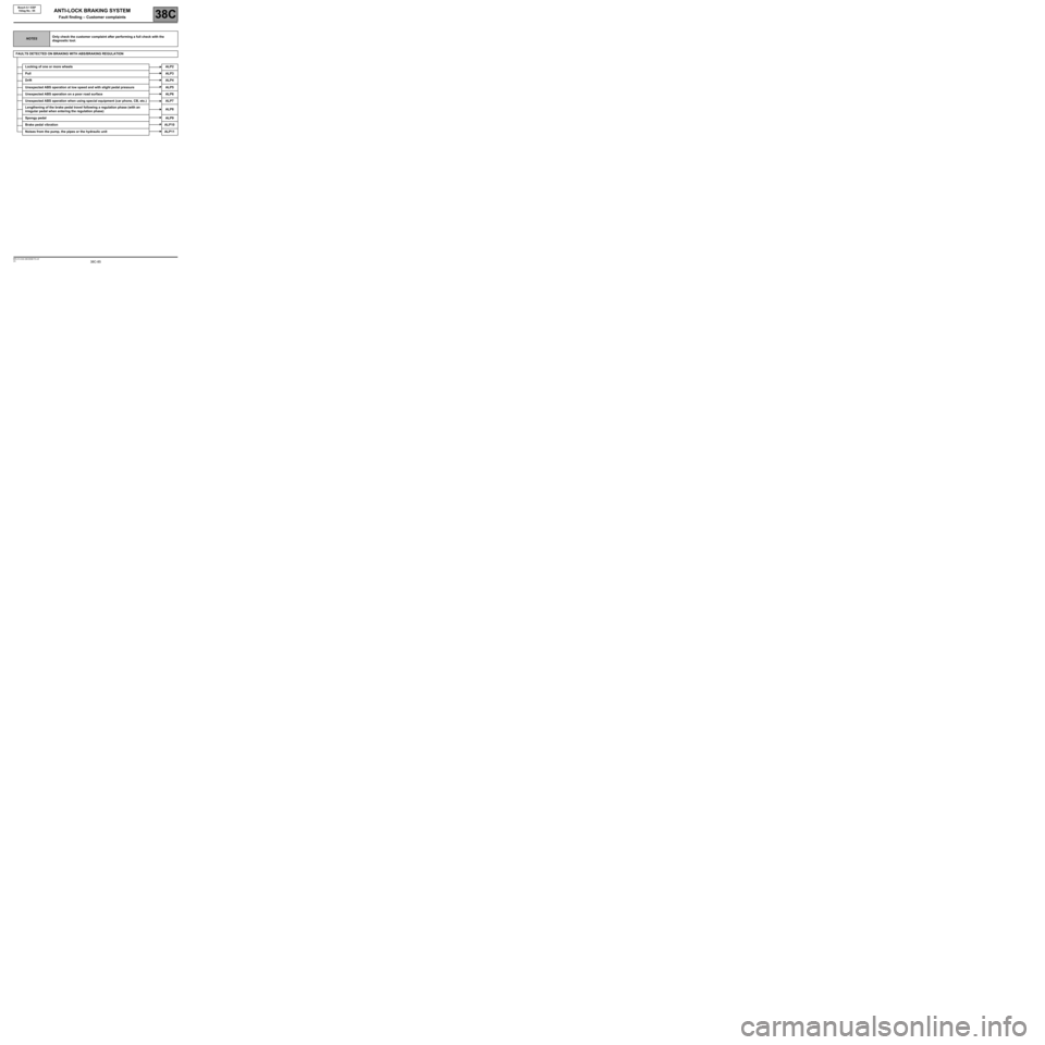
NOTESOnly check the customer complaint after performing a full check with the
diagnostic tool.
FAULTS DETECTED ON BRAKING WITH ABS/BRAKING REGULATION
Locking of one or more wheels ALP2
PullALP3
DriftALP4
Unexpected ABS operation at low speed and with slight pedal pressure ALP5
Unexpected ABS operation on a poor road surface ALP6
Unexpected ABS operation when using special equipment (car phone, CB, etc.) ALP7
Lengthening of the brake pedal travel following a regulation phase (with an
irregular pedal when entering the regulation phase)ALP8
Spongy pedalALP9
Brake pedal vibrationALP10
Noises from the pump, the pipes or the hydraulic unit ALP11
ANTI-LOCK BRAKING SYSTEM
Fault finding – Customer complaints
Page 86 of 101
38C-86V3 MR-413-X44-38C050$170.mif
ANTI-LOCK BRAKING SYSTEM
Fault finding – Customer complaints38C
Bosch 8.1 ESP
Vdiag No.: 05
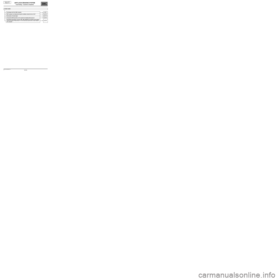
OTHER CASES
No dialogue with the ABS computer ALP1
ESP computer not detected during the multiplex network test on CLIP ALP12
Illumination of brake lights ALP 13
Unexpected ABS operation at low speeds and slight pedal pressure ALP14
Intermittent illumination of brake, ESP, ABS, SERVICE and STOP warning lights
and the message "Brake failure" on the instrument panel with no fault codes in
the computerALP15
Page 89 of 101
38C-89
AFTER REPAIRClear the computer fault memory.
Carry out a road test followed by another check with the diagnostic tool.
V3 MR-413-X44-38C050$180.mif
ANTI-LOCK BRAKING SYSTEM
Fault finding – Fault finding chart38C
Bosch 8.1 ESP
Vdiag No.: 05
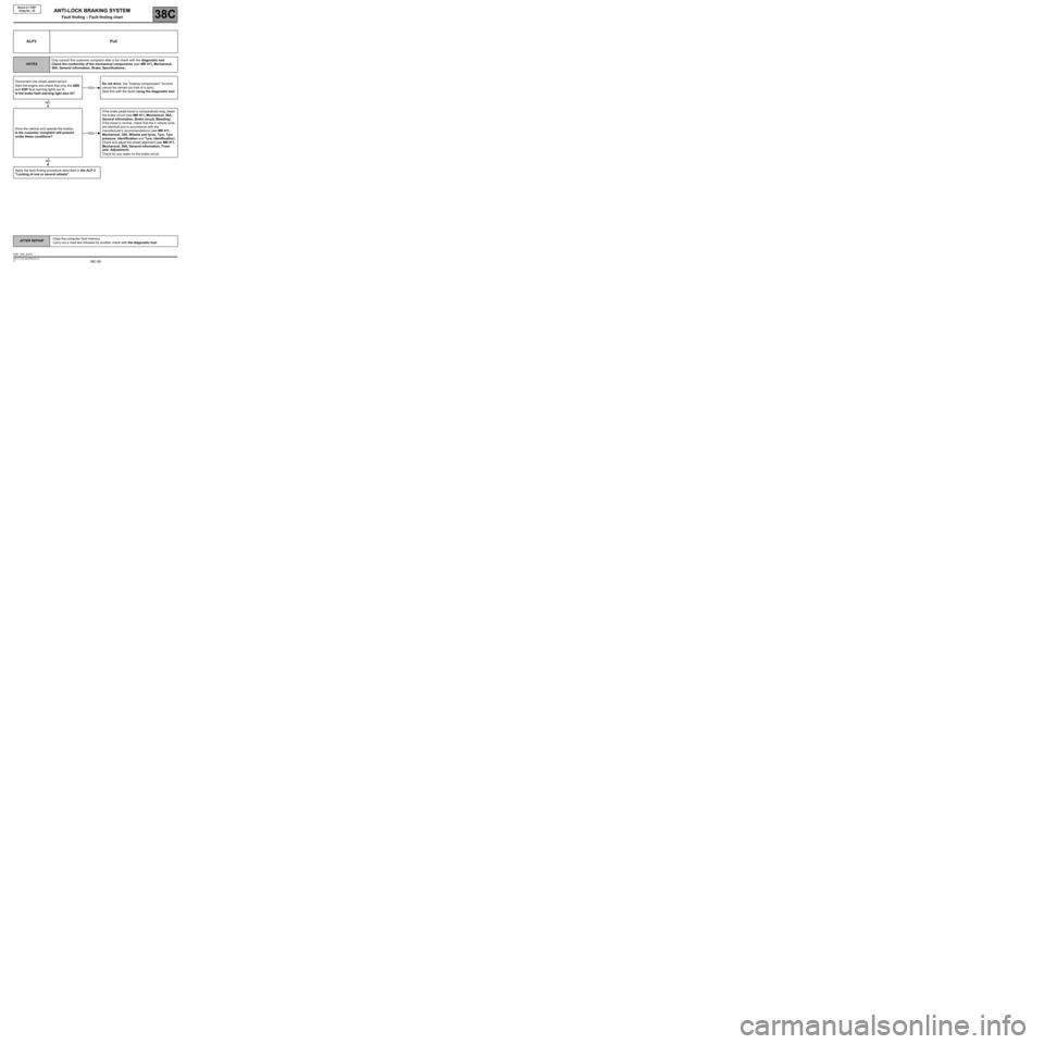
ALP3 Pull
NOTESOnly consult this customer complaint after a full check with the diagnostic tool.
Check the conformity of the mechanical components (see MR 411, Mechanical,
30A, General information, Brake, Specifications).
Disconnect one wheel speed sensor.
Start the engine and check that only the ABS
and ESP fault warning lights are lit.
Is the brake fault warning light also lit?Do not drive, the "braking compensator" function
cannot be carried out (risk of a spin).
Deal first with the faults using the diagnostic tool.
Drive the vehicle and operate the brakes.
Is the customer complaint still present
under these conditions?If the brake pedal travel is comparatively long, bleed
the brake circuit (see MR 411, Mechanical, 30A,
General information, Brake circuit, Bleeding).
If the travel is normal, check that the 4 vehicle tyres
are identical and in accordance with the
manufacturer's recommendations (see MR 411,
Mechanical, 35A, Wheels and tyres, Tyre, Tyre
pressure, Identification and Tyre, Identification).
Check and adjust the wheel alignment (see MR 411,
Mechanical, 30A, General information, Front
axle, Adjustment).
Check for any leaks on the brake circuit.
Apply the fault finding procedure described in the ALP 2
"Locking of one or several wheels".
YES
NO
YES
NO
ESP_V05_ALP3
Page 90 of 101
38C-90
AFTER REPAIRClear the computer fault memory.
Carry out a road test followed by another check with the diagnostic tool.
V3 MR-413-X44-38C050$180.mif
ANTI-LOCK BRAKING SYSTEM
Fault finding – Fault finding chart38C
Bosch 8.1 ESP
Vdiag No.: 05
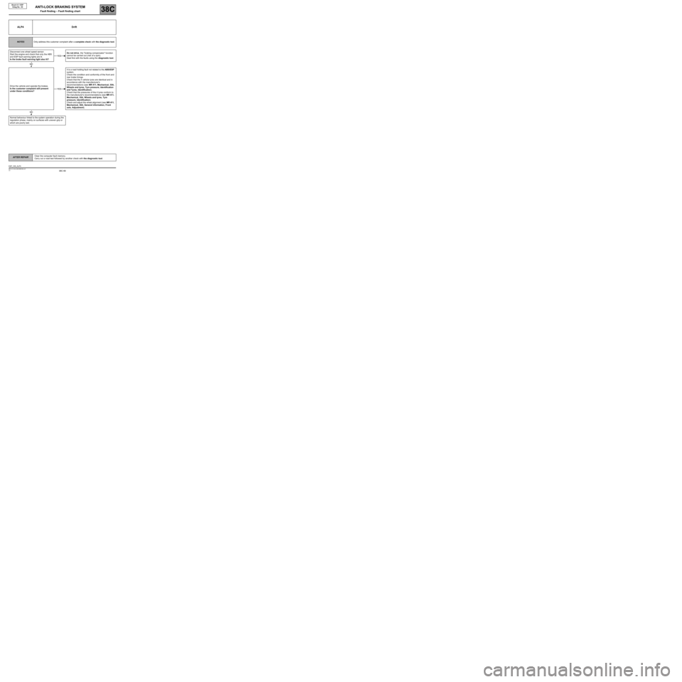
ALP4 Drift
NOTESOnly address this customer complaint after a complete check with the diagnostic tool.
Disconnect one wheel speed sensor.
Start the engine and check that only the ABS
and ESP fault warning lights are lit.
Is the brake fault warning light also lit?Do not drive, the "braking compensator" function
cannot be carried out (risk of a spin).
Deal first with the faults using the diagnostic tool.
Drive the vehicle and operate the brakes.
Is the customer complaint still present
under these conditions?It is a road holding fault not related to the ABS/ESP
system.
Check the condition and conformity of the front and
rear brake linings.
Check that the 4 vehicle tyres are identical and in
accordance with the manufacturer's
recommendations (see MR 411, Mechanical, 35A,
Wheels and tyres, Tyre pressure, Identification
and Tyres, Identification).
Check that the pressures of the 4 tyres conform to
the manufacturer's recommendations (see MR 411,
Mechanical, 35A, Wheels and tyres, Tyre
pressure, Identification).
Check and adjust the wheel alignment (see MR 411,
Mechanical, 30A, General information, Front
axle, Adjustment).
Normal behaviour linked to the system operation during the
regulation phase, mainly on surfaces with uneven grip or
which are poorly laid.
YES
NO
YES
NO
ESP_V05_ALP4