RENAULT TWINGO 2009 2.G Chasiss Workshop Manual
Manufacturer: RENAULT, Model Year: 2009, Model line: TWINGO, Model: RENAULT TWINGO 2009 2.GPages: 281
Page 141 of 281
35A-1
WHEELS AND TYRES
Wheel: Removal - Refitting
35A
The removal - refitting procedure is the same for all
wheels.
REMOVAL
I - REMOVAL PREPARATION OPERATION
aPosition the vehicle on a two-post lift (see Vehicle:
Towing and lifting) (02A, Lifting equipment).
aRelease the parking brake.
aRemove the trim.
aPosition the wheel so that the valve is at the top.
aMark the position of the wheel on the hub.
II - OPERATION FOR REMOVAL OF PART
CONCERNED
aLoosen the wheel bolts with the wheel on the
ground.
aRaise the lift.
aRemove:
-the wheel bolts,
-the wheel.
If the wheel cannot be removed after the bolt has
been undone:
aPosition all the wheel bolts.
aTighten the wheel bolts to bring all the bolt heads
into contact with the wheel.
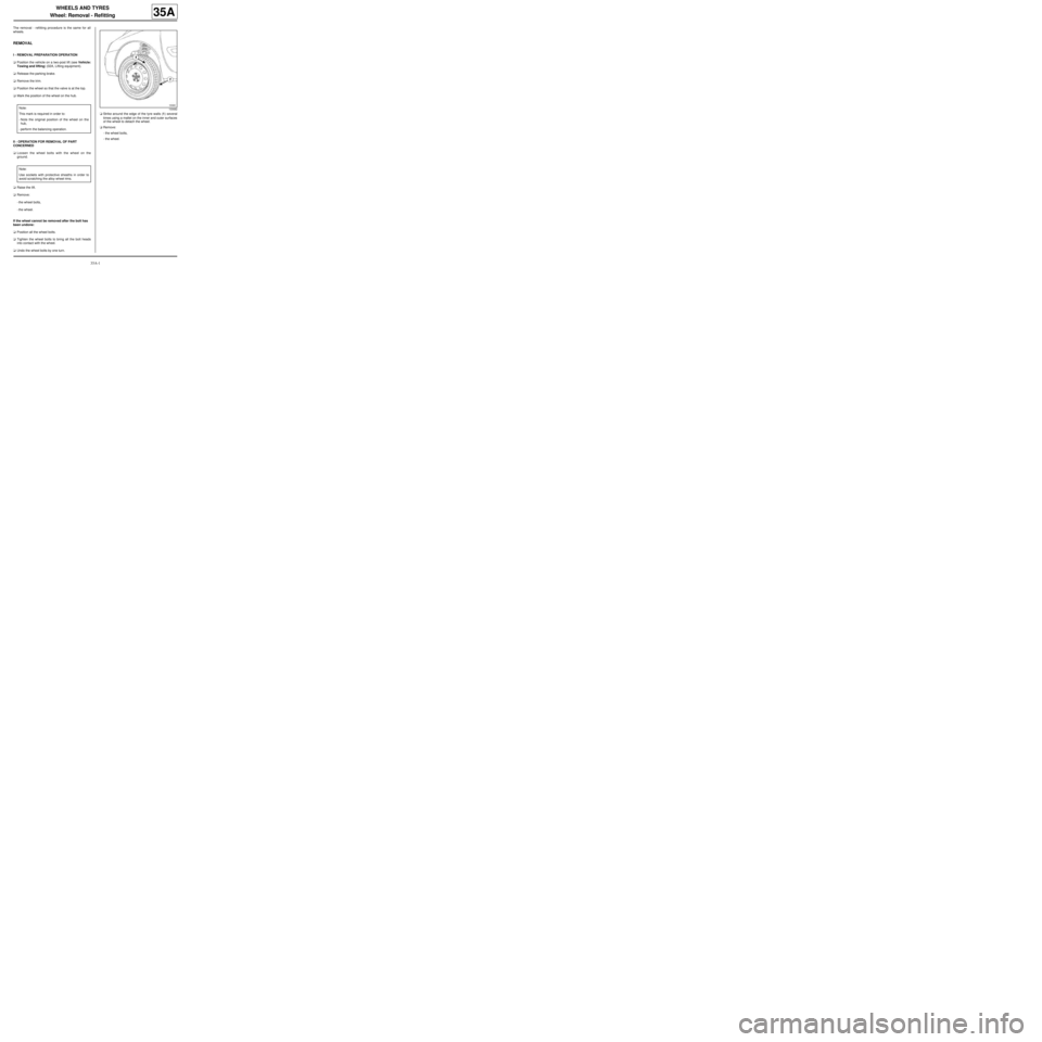
aUndo the wheel bolts by one turn.aStrike around the edge of the tyre walls (1) several
times using a mallet on the inner and outer surfaces
of the wheel to detach the wheel.
aRemove:
-the wheel bolts,
-the wheel. Note:
This mark is required in order to:
-Note the original position of the wheel on the
hub,
-perform the balancing operation.
Note:
Use sockets with protective sheaths in order to
avoid scratching the alloy wheel rims.
100682
Page 142 of 281
35A-2
WHEELS AND TYRES
Wheel: Removal - Refitting
35A
If this procedure does not work:
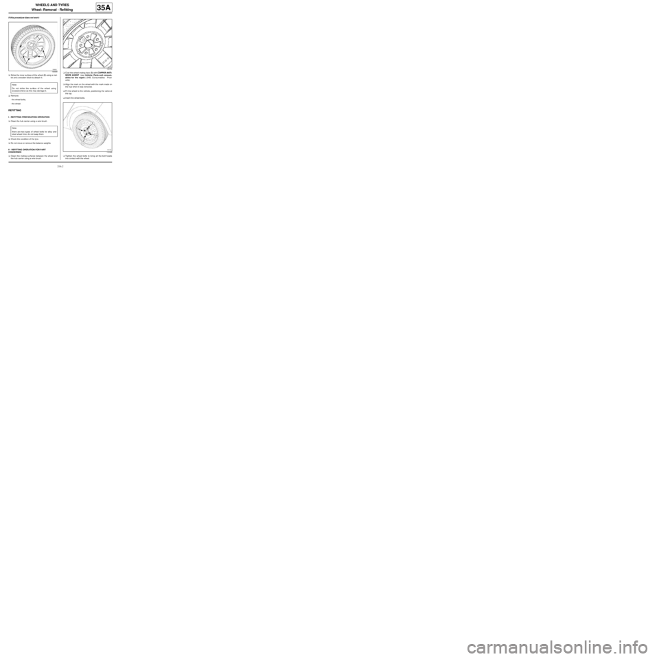
aStrike the inner surface of the wheel (2) using a mal-
let and a wooden block to detach it.
aRemove:
-the wheel bolts,
-the wheel.
REFITTING
I - REFITTING PREPARATION OPERATION
aClean the hub carrier using a wire brush.
aCheck the condition of the tyre.
aDo not move or remove the balance weights.
II - REFITTING OPERATION FOR PART
CONCERNED
aClean the mating surfaces between the wheel and
the hub carrier using a wire brush.aCoat the wheel-mating face (3) with COPPER ANTI-
SEIZE AGENT (see Vehicle: Parts and consum-
ables for the repair) (04B, Consumables - Prod-
ucts).
aAlign the mark on the wheel with the mark made on
the hub when it was removed.
aFit the wheel to the vehicle, positioning the valve at
the top.
aInsert the wheel bolts.
aTighten the wheel bolts to bring all the bolt heads
into contact with the wheel.
106089
Note:
Do not strike the surface of the wheel using
excessive force as this may damage it.
Note:
there are two types of wheel bolts for alloy and
steel wheel rims; do not swap them.
124750
113180
Page 143 of 281
35A-3
WHEELS AND TYRES
Wheel: Removal - Refitting
35A
aPretighten the wheel bolts to 30 N.m, with the wheel
suspended, starting with the bolts at the bottom.
aRotate the wheel through 180˚ to bring the valve into
the bottom position.
aPosition the vehicle on its wheels.
aTorque tighten the wheel bolts in order (see 30A,
General information, Front axle system: Tighten-
ing torque, page 30A-27) (30A, General informa-
tion).
aRefit the trim piece.Note:
Use sockets with protective sheaths in order to
avoid scratching the alloy wheel rims.
Page 144 of 281
35A-4
WHEELS AND TYRES
Wheel: Balancing
35A
I - PREREQUISITES FOR WHEEL BALANCING
aWheel balancing is a measurement operation.
Several conditions must be met to achieve a reliable
result in a single operation.
The wheel balancer must be installed in accordance
with the manufacturer's instructions.
It is essential to calibrate the balancer according to
the frequency recommended by the manufacturer.
Do not grease the threaded shaft.
Check the condition of the supports, centring com-
ponents and mountings.
Replace any faulty parts (see manufacturer's in-
structions).
The wheel and the wheel balancer must be clean.
Driver's perception
aIf the wheels are not correctly balanced this causes
the steering wheel and/or the vehicle floor to vibrate.
These vibrations appear between 54 mph (90 km/h)
and 90 mph (150 km/h).
II - BALANCING PREPARATION OPERATION
aAdjust the tyre pressure (see 35A, Wheels and ty-
res, Tyre pressure: Identification, page 35A-10) .
aAlways carry out a road test for a minimum distance
of 1 mile (2 km) before balancing the wheels, in or-
der to remove any flat spots on the tread caused by
the vehicle being immobilised.
aActions to be carried out immediately after the test
drive:
-Position the vehicle on a two-post vehicle lift (see
Vehicle: Towing and lifting) ,
-raise the vehicle,
-leave the four wheels hanging free,
-release the parking brake.a
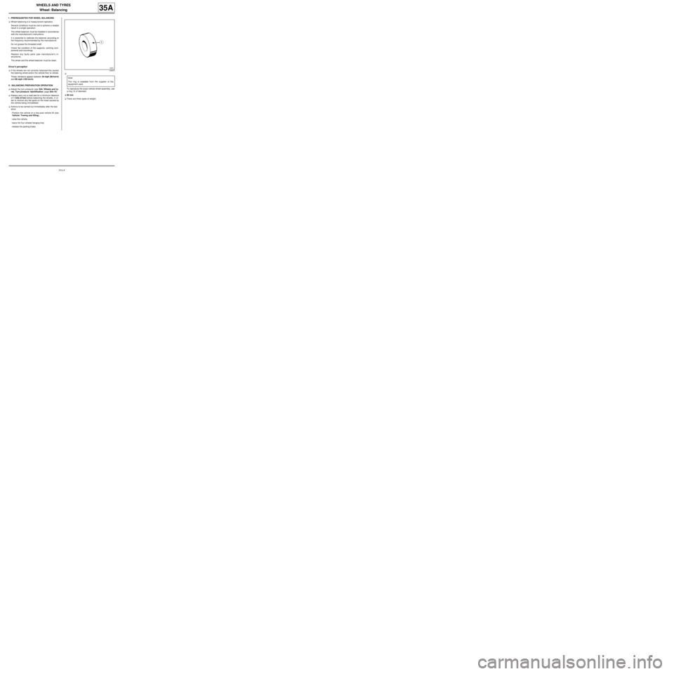
To reproduce the exact vehicle wheel assembly, use
a ring (1) of diameter:
a60 mm
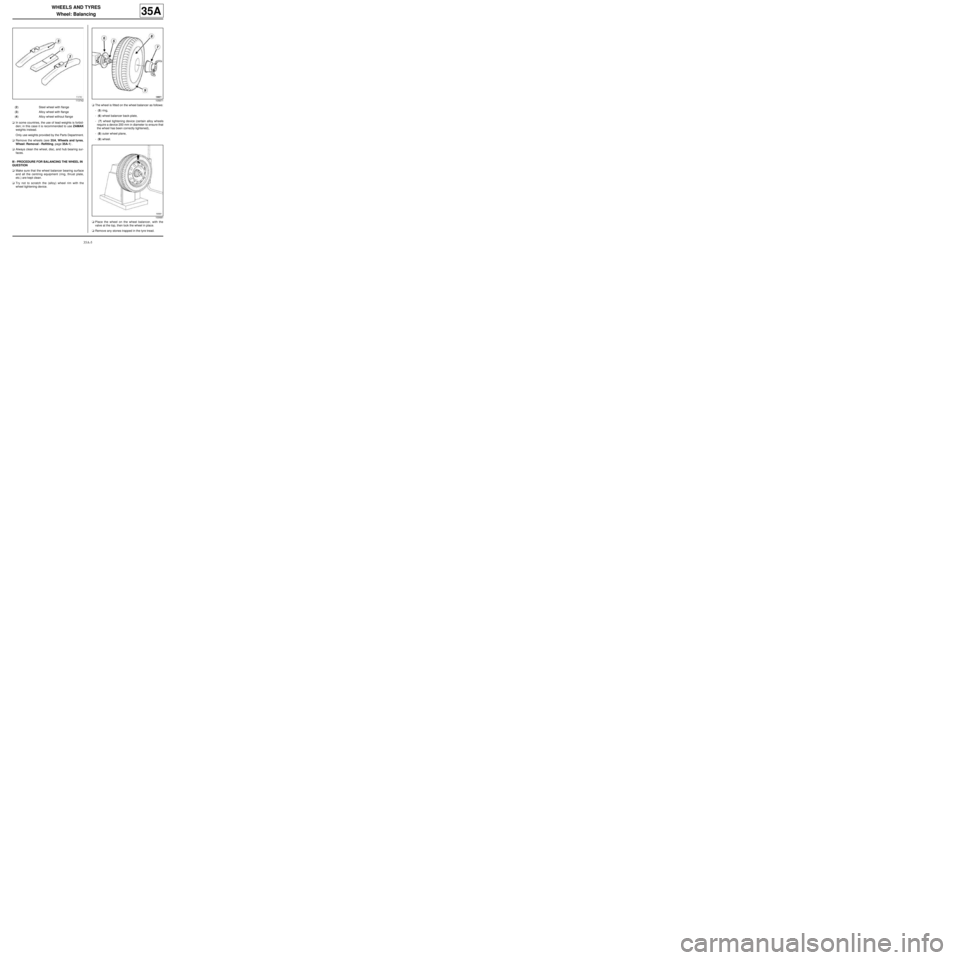
aThere are three types of weight:
105870
Note:
The ring is available from the supplier of the
equipment used.
Page 145 of 281
35A-5
WHEELS AND TYRES
Wheel: Balancing
35A
aIn some countries, the use of lead weights is forbid-
den; in this case it is recommended to use ZAMAK
weights instead.
Only use weights provided by the Parts Department.
aRemove the wheels (see 35A, Wheels and tyres,
Wheel: Removal - Refitting, page 35A-1) .
aAlways clean the wheel, disc, and hub bearing sur-
faces.
III - PROCEDURE FOR BALANCING THE WHEEL IN
QUESTION
aMake sure that the wheel balancer bearing surface
and all the centring equipment (ring, thrust plate,
etc.) are kept clean.
aTry not to scratch the (alloy) wheel rim with the
wheel tightening device.aThe wheel is fitted on the wheel balancer as follows:
- (5) ring,
- (6) wheel balancer back-plate,
- (7) wheel tightening device (certain alloy wheels
require a device 200 mm in diameter to ensure that
the wheel has been correctly tightened),
- (8) outer wheel plane,
- (9) wheel.
aPlace the wheel on the wheel balancer, with the
valve at the top, then lock the wheel in place.
aRemove any stones trapped in the tyre tread.
113742
(2) Steel wheel with flange
(3) Alloy wheel with flange
(4) Alloy wheel without flange
105871
100681
Page 146 of 281
35A-6
WHEELS AND TYRES
Wheel: Balancing
35A
aEnter the specific wheel parameters when starting
the wheel balancer.
aStart the wheel balancer and check the wheel bal-
ance, which should be 0 g on each plane of the
wheel.
aIf this is not the case, remove the old wheel balanc-
ing weights and repeat the wheel balancing proce-
dure, checking that the wheel balance equals 0 on
each wheel plane.
IV - FINAL OPERATION
aRefit the wheel (see 35A, Wheels and tyres,
Wheel: Removal - Refitting, page 35A-1) . WARNING
To avoid detachment of the balance weights, use
only weights which correspond to the vehicle
wheel rims.
Page 147 of 281
35A-7
WHEELS AND TYRES
Tyres: Identification
35A
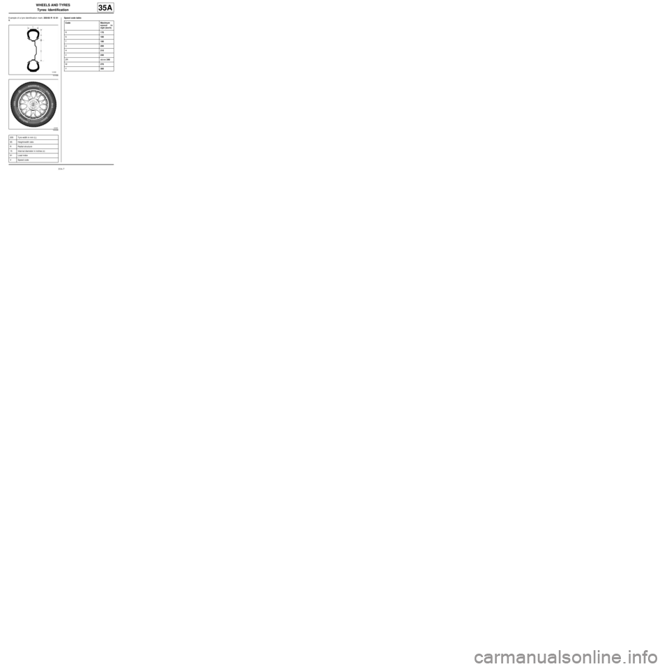
Example of a tyre identification mark: 205/65 R 15 91
V.Speed code table:
101008
123448
205 Tyre width in mm (L)
65 Height/width ratio
RRadial structure
15 Internal diameter in inches (c)
91 Load index
VSpeed code
Code Maximum
speed in
mph (km/h)
R170
S180
T190
U200
H210
V240
ZR above 240
W270
Y300
Page 148 of 281
35A-8
WHEELS AND TYRES
Tyres: Removal - Refitting
35A
REMOVAL
I - REMOVAL PREPARATION OPERATION
aPosition the vehicle on a two-post lift (see Vehicle:
Towing and lifting) (02A, Lifting equipment).
aRemove:
-the wheel in question (see 35A, Wheels and tyres,
Wheel: Removal - Refitting, page 35A-1) ,
-the balance weights,
-the valve mechanism.
II - OPERATION FOR REMOVAL OF PART
CONCERNED
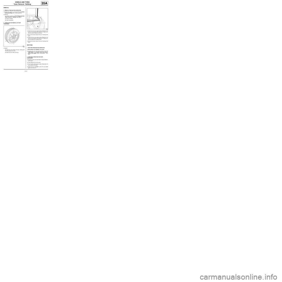
aDetach:
-the bead from the outside of the tyre, starting with
the side opposite the valve,
-the bead from the inside of the tyre.aPosition the tyre lever approximately 15 cm from the
valve on the outside of the wheel rim in order to re-
move the exterior bead from the tyre.
aRemove the exterior bead of the tyre, finishing at the
valve.
aPosition the tyre lever approximately 15 cm from the
valve on the outside of the wheel rim in order to re-
move the bead from inside the tyre.
aRemove the interior bead of the tyre, finishing at the
valve.
REFITTING
I - REFITTING PREPARATION OPERATION
aparts always to be replaced: Tyre valve
aLubricate the two tyre beads correctly using the
TYRE PASTE (see Vehicle: Parts and consum-
ables for the repair) (04B, Consumables - Prod-
ucts).
II - REFITTING OPERATION FOR PART
CONCERNED
aEngage the lower tyre bead approximately 15 cm af-
ter the valve.
aFinish fitting the tyre at the valve.
aFit the exterior bead approximately 15 cm after the
valve using the tyre lever.
aInflate the tyre to 3.5 bar to press the tyre beads
against the wheel rim.
18884
18885
Page 149 of 281
35A-9
WHEELS AND TYRES
Tyres: Removal - Refitting
35A
III - FINAL OPERATION
aRefit the valve mechanism.
aInflate the tyre to the recommended pressure (see
35A, Wheels and tyres, Tyre pressure: Identifica-
tion, page 35A-10) .
aBalance the wheel (see 35A, Wheels and tyres,
Wheel: Balancing, page 35A-4) .
aRefit the wheel in question (see 35A, Wheels and
tyres, Wheel: Removal - Refitting, page 35A-1) . Note:
It is not necessary to drive the vehicle before and
after a new wheel is balanced.
Page 150 of 281
35A-10
WHEELS AND TYRES
Tyre pressure: Identification
35A
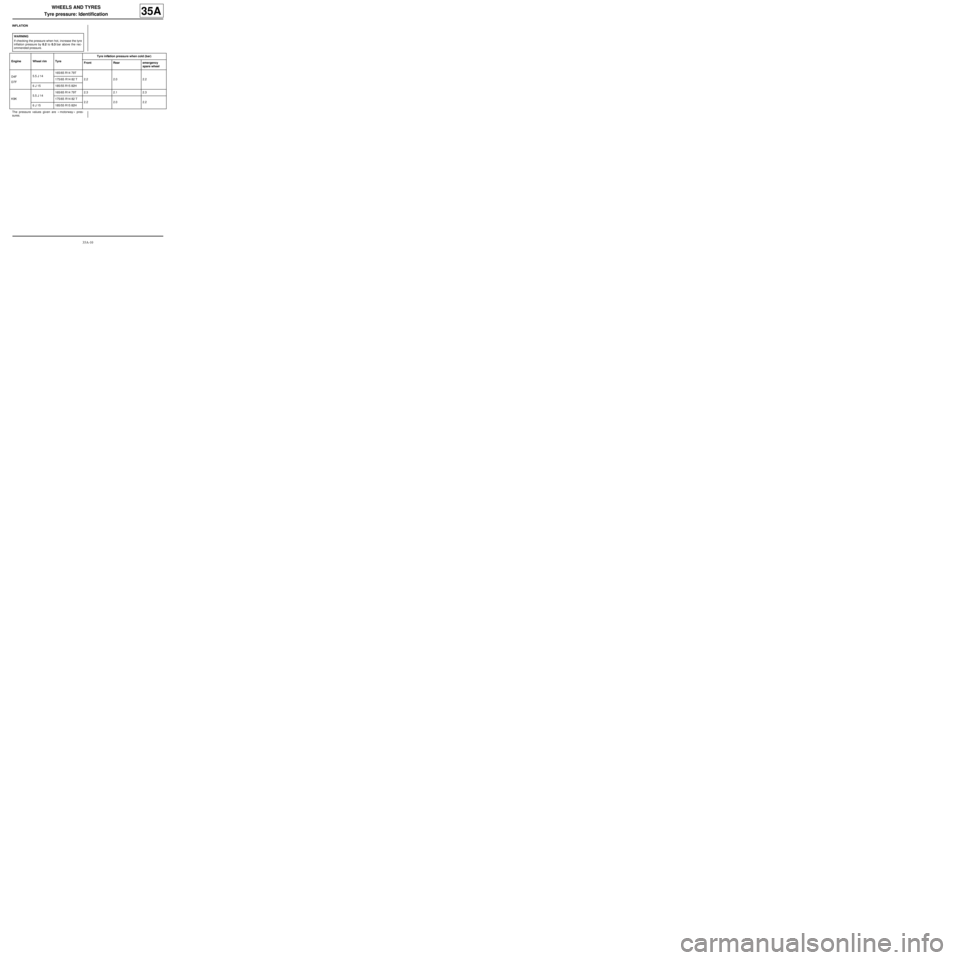
INFLATION
The pressure values given are « motorway » pres-
sures.WARNING
If checking the pressure when hot, increase the tyre
inflation pressure by 0.2 to 0.3 bar above the rec-
ommended pressure.
Engine Wheel rim TyreTyre inflation pressure when cold (bar)
Front Rear emergency
spare wheel
D4F
D7F5.5 J 14165/65 R14 79T
2.2 2.0 2.2 175/65 R14 82 T
6 J 15 185/55 R15 82H
K9K5.5 J 14165/65 R14 79T 2.3 2.1 2.3
175/65 R14 82 T
2.2 2.0 2.2
6 J 15 185/55 R15 82H