air RENAULT TWINGO 2009 2.G Chasiss Owner's Manual
[x] Cancel search | Manufacturer: RENAULT, Model Year: 2009, Model line: TWINGO, Model: RENAULT TWINGO 2009 2.GPages: 281
Page 59 of 281
31A-16
FRONT AXLE COMPONENTS
Front brake calliper mounting: Removal - Refitting
EQ UIPMENT LEVEL SPORT
31A
REMOVAL
I - REMOVAL PREPARATION OPERATION
aPosition the vehicle on a two-post lift (see Vehicle:
Towing and lifting) (02A, Lifting equipment).
aRemove:
-the front wheel (see 35A, Wheels and tyres,
Wheel: Removal - Refitting, page 35A-1) ,
-the front brake pads (see 31A, Front axle compo-
nents, Front brake pads: Removal - Refitting,
page 31A-1) .II - REMOVAL OPERATION
aRemove:
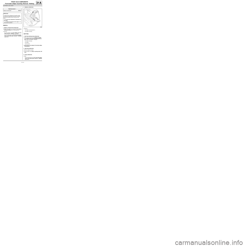
-the calliper mounting bolts (1) ,
-the calliper mounting.
REFITTING
I - REFITTING PREPARATION OPERATION
aClean using a wire brush and BRAKE CLEANER
(see Vehicle: Parts and consumables for the re-
pair) (04B, Consumables - Products):
-the calliper mounting,
-the calliper,
-the hub carrier.
aparts always to be replaced: Front brake calliper
mounting bolt.
II - REFITTING OPERATION
aRefit the calliper mounting.
aTorque tighten the calliper mounting bolts (100
N.m).
III - FINAL OPERATION
aRefit:
-the front brake pads (see 31A, Front axle compo-
nents, Front brake pads: Removal - Refitting,
page 31A-1) , Tightening torquesm
calliper mounting bolts100 N.m
IMPORTANT
To avoid all risk of damage to the systems, apply
the safety and cleanliness instructions and opera-
tion recommendations before carrying out any
repair:
- (see Front axle components: Precautions for
the repair) ,
- (see Vehicle: Precautions for the repair) (01D,
Mechanical introduction).
145125
Page 62 of 281
31A-19
FRONT AXLE COMPONENTS
Front brake disc: Removal - Refitting
31A
Brake discs cannot be reground. If there is excessive
scoring or wear, they will need to be replaced (see
30A, General information, Brake: Specifications,
page 30A-19) .
REMOVAL
I - REMOVAL PREPARATION OPERATION
aPosition the vehicle on a two-post lift (see Vehicle:
Towing and lifting) (02A, Lifting equipment).
aSet the wheels straight ahead.
aRemove the front wheel (see 35A, Wheels and ty-
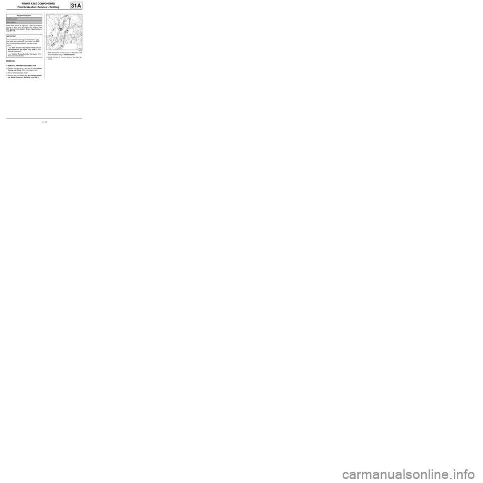
res, Wheel: Removal - Refitting, page 35A-1) .aMark the position of the cap (1) on the base of the
shock absorber using a indelible pencil.
aUnclip the cap (1) from the base of the shock ab-
sorber. Equipment required
indelible pencil
par ts washer
IMPORTANT
To avoid all risk of damage to the systems, apply
the safety and cleanliness instructions and opera-
tion recommendations before carrying out any
repair:
- (see 30A, General information, Brake circuit:
Precautions for the repair, page 30A-2) (30A,
General information),
- (see Vehicle: Precautions for the repair) (01D,
Mechanical introduction).
126339
Page 63 of 281
31A-20
FRONT AXLE COMPONENTS
Front brake disc: Removal - Refitting
31A
aRemove the brake pads (see 31A, Front axle com-
ponents, Front brake pads: Removal - Refitting,
page 31A-1)
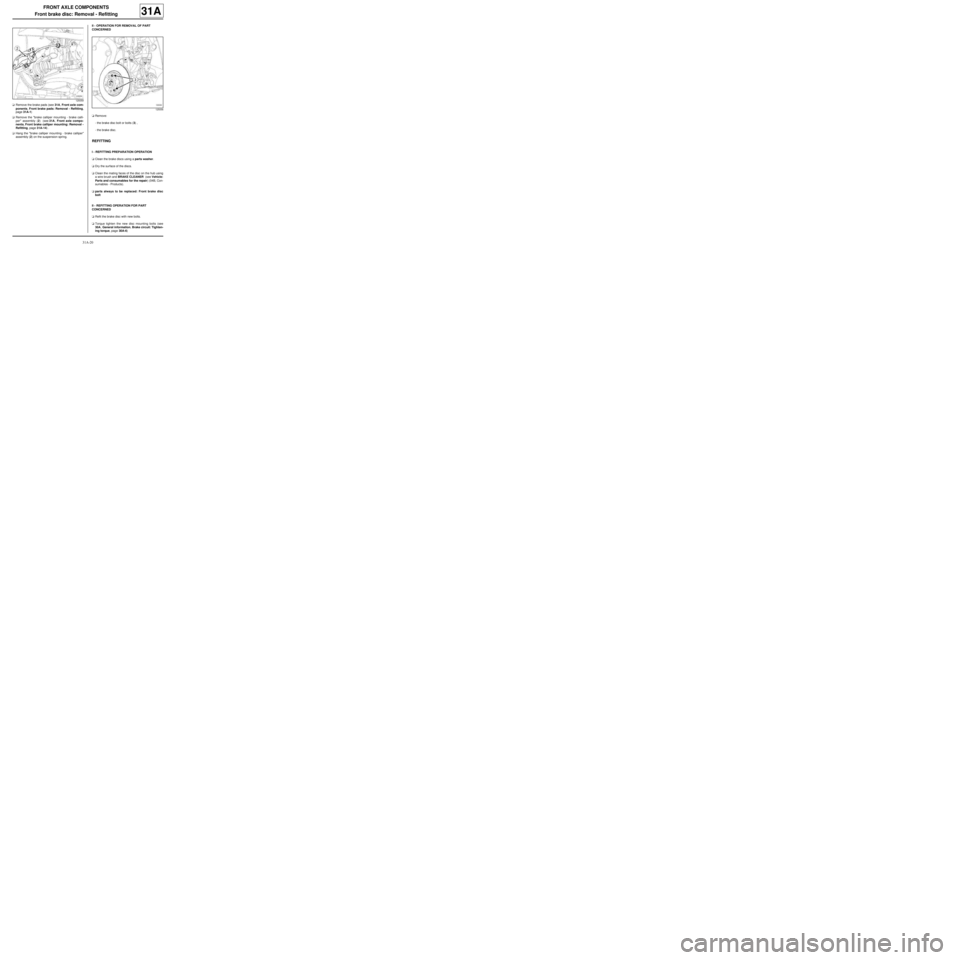
aRemove the "brake calliper mounting - brake calli-
per" assembly (2) (see 31A, Front axle compo-
nents, Front brake calliper mounting: Removal -
Refitting, page 31A-14) .
aHang the "brake calliper mounting - brake calliper"
assembly (2) on the suspension spring.II - OPERATION FOR REMOVAL OF PART
CONCERNED
aRemove:
-the brake disc bolt or bolts (3) ,
-the brake disc.
REFITTING
I - REFITTING PREPARATION OPERATION
aClean the brake discs using a parts washer.
aDry the surface of the discs.
aClean the mating faces of the disc on the hub using
a wire brush and BRAKE CLEANER (see Vehicle:
Parts and consumables for the repair) (04B, Con-
sumables - Products).
aparts always to be replaced: Front brake disc
bolt
II - REFITTING OPERATION FOR PART
CONCERNED
aRefit the brake disc with new bolts.
aTorque tighten the new disc mounting bolts (see
30A, General information, Brake circuit: Tighten-
ing torque, page 30A-6)
125059
125056
Page 90 of 281
31A-47
FRONT AXLE COMPONENTS
Front axle subframe: Removal - Refitting
31A
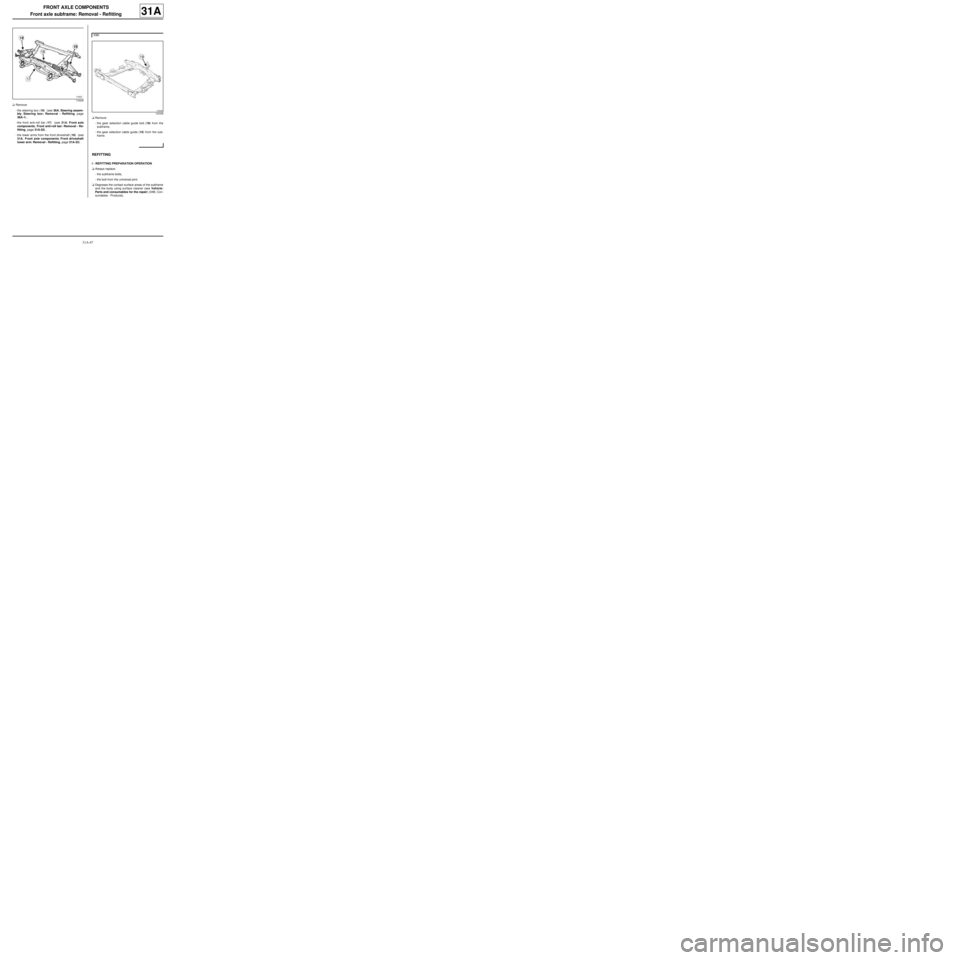
aRemove:
-the steering box (16) (see 36A, Steering assem-
bly, Steering box: Removal - Refitting, page
36A-1) ,
-the front anti-roll bar (17) (see 31A, Front axle
components, Front anti-roll bar: Removal - Re-
fitting, page 31A-52) ,
-the lower arms from the front driveshaft (18) (see
31A, Front axle components, Front driveshaft
lower arm: Removal - Refitting, page 31A-33) .aRemove:
-the gear selection cable guide bolt (19) from the
subframe,
-the gear selection cable guide (19) from the sub-
frame.
REFITTING
I - REFITTING PREPARATION OPERATION
aAlways replace:
-the subframe bolts,
-the bolt from the universal joint.
aDegrease the contact surface areas of the subframe
and the body using surface cleaner (see Vehicle:
Parts and consumables for the repair) (04B, Con-
sumables - Products).
119429
K9K
124348
Page 100 of 281
33A-2
REAR AXLE COMPONENTS
Rear brake pads: Removal - Refitting
EQ UIPMENT LEVEL SPORT
33A
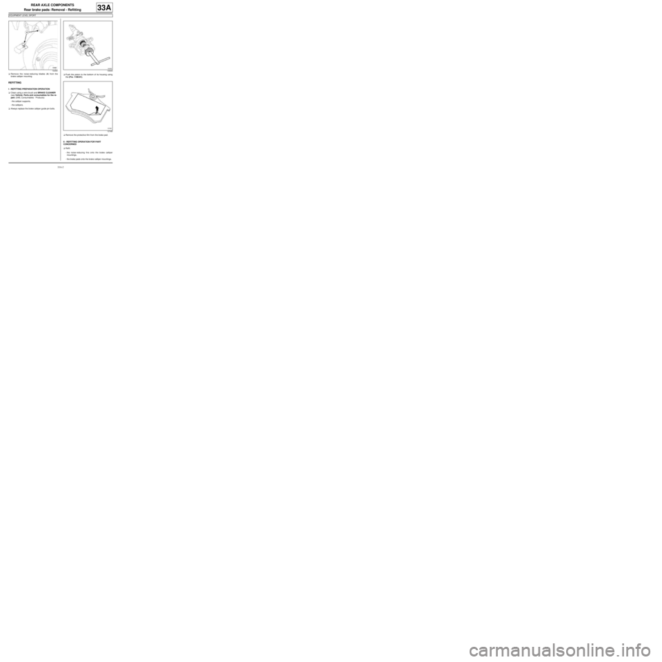
aRemove the noise-reducing blades (4) from the
brake calliper mounting.
REFITTING
I - REFITTING PREPARATION OPERATION
aClean using a wire brush and BRAKE CLEANER
(see Vehicle: Parts and consumables for the re-
pair) (04B, Consumables - Products):
-the calliper supports,
-the callipers.
aAlways replace the brake calliper guide pin bolts.aPush the piston to the bottom of its housing using
the (Fre. 1190-01).
aRemove the protective film from the brake pad.
II - REFITTING OPERATION FOR PART
CONCERNED
aRefit:
-the noise-reducing fins onto the brake calliper
mountings,
-the brake pads onto the brake calliper mountings.
132464106309
127485
Page 105 of 281

33A-7
REAR AXLE COMPONENTS
Rear brake calliper: Removal - Refitting
EQ UIPMENT LEVEL SPORT
33A
REMOVAL
I - REMOVAL PREPARATION OPERATION
aPosition the vehicle on a two-post lift (see Vehicle:
Towing and lifting) (02A, Lifting equipment).
aRelease the parking brake.
aPosition a pedal press on the brake pedal to limit
the outflow of brake fluid.
aRemove the rear wheel (see 35A, Wheels and ty-
res, Wheel: Removal - Refitting, page 35A-1) .II - OPERATION FOR REMOVAL OF PART
CONCERNED
aUnclip the parking brake cable from the brake calli-
per at (1) .
aMove aside the parking brake cable.
aLoosen the calliper brake pipe union (2) .
aRemove:
-the brake calliper guide pin bolts (3) ,
-the brake calliper from the mounting,
-the union between the brake pipe and the calliper,
-the brake calliper.
REFITTING
I - REFITTING PREPARATION OPERATION
aClean using a wire brush and BRAKE CLEANER
(see Vehicle: Parts and consumables for the re-
pair) (04B, Consumables - Products):
-the calliper supports,
-the callipers.
aAlways replace the brake calliper guide pin bolts. Special tooling required
Fre. 1190-01Brake calliper piston return
tool.
Equipment required
pedal press
Tightening torquesm
new bolts on the brake
calliper guide pins35 N.m
brake pipe union on the
calliper13 N.m
WARNING
To avoid damaging the parking brake cable protec-
tors and causing premature wear of the system, do
not handle the cables with a tool.
132468
Page 108 of 281
33A-10
REAR AXLE COMPONENTS
Rear brake calliper mounting: Removal - Refitting
EQ UIPMENT LEVEL SPORT
33A
REFITTING
I - REFITTING PREPARATION OPERATION
aClean using a wire brush and BRAKE CLEANER
(see Vehicle: Parts and consumables for the re-
pair) (04B, Consumables - Products):
-the calliper supports,
-the callipers.
aAlways replace:
-the calliper mounting bolts,
-the calliper guide pin bolts.
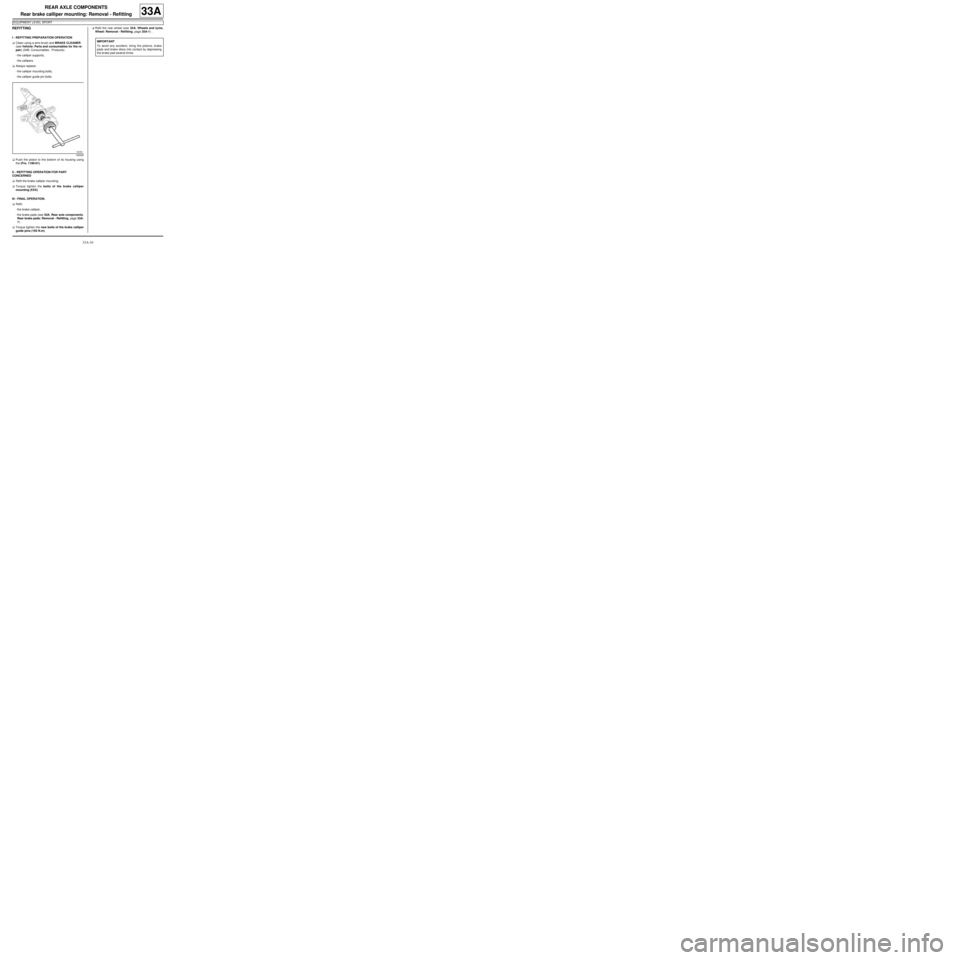
aPush the piston to the bottom of its housing using
the (Fre. 1190-01).
II - REFITTING OPERATION FOR PART
CONCERNED
aRefit the brake calliper mounting.
aTorque tighten the bolts of the brake calliper
mounting (XXX).
III - FINAL OPERATION.
aRefit:
-the brake calliper,
-the brake pads (see 33A, Rear axle components,
Rear brake pads: Removal - Refitting, page 33A-
1) .
aTorque tighten the new bolts of the brake calliper
guide pins (105 N.m).aRefit the rear wheel (see 35A, Wheels and tyres,
Wheel: Removal - Refitting, page 35A-1) .
106309
IMPORTANT
To avoid any accident, bring the pistons, brake
pads and brake discs into contact by depressing
the brake pad several times.
Page 110 of 281
33A-12
REAR AXLE COMPONENTS
Rear brake disc: Removal - Refitting
EQ UIPMENT LEVEL SPORT
33A
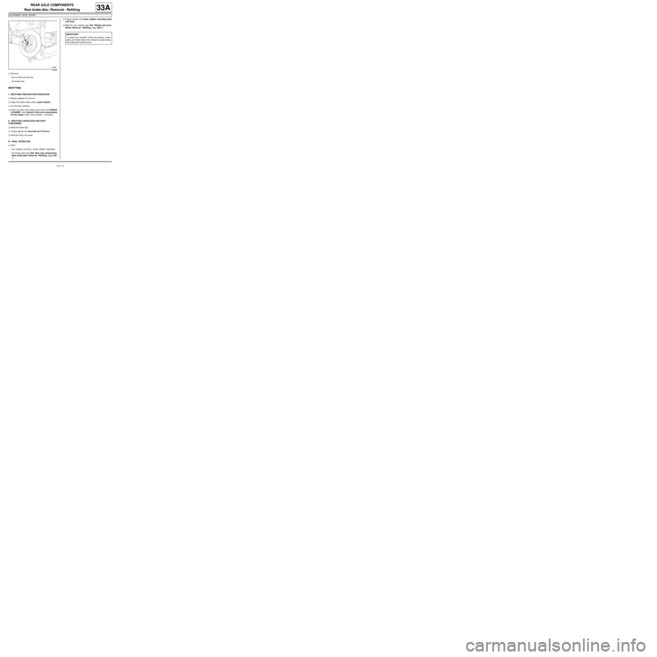
aRemove:
-the nut (3) from the hub,
-the brake disc.
REFITTING
I - REFITTING PREPARATION OPERATION
aAlways replace the hub nut.
aClean the brake discs using a parts washer.
aDry the disc surfaces.
aClean the stub axle using a wire brush and BRAKE
CLEANER (see Vehicle: Parts and consumables
for the repair) (04B, Consumables - Products).
II - REFITTING OPERATION FOR PART
CONCERNED
aRefit the brake disc.
aTorque tighten the new hub nut (175 N.m ).
aRefit the hub's nut cover.
III - FINAL OPERATION.
aRefit:
-the "calliper mounting - brake calliper" assembly,
-the brake pads (see 33A, Rear axle components,
Rear brake pads: Removal - Refitting, page 33A-
1) .aTorque tighten the brake calliper mounting bolts
(105 N.m).
aRefit the rear wheels (see 35A, Wheels and tyres,
Wheel: Removal - Refitting, page 35A-1) .
132455
IMPORTANT
To avoid any accident, bring the pistons, brake
pads and brake discs into contact by depressing
the brake pad several times.
Page 142 of 281
35A-2
WHEELS AND TYRES
Wheel: Removal - Refitting
35A
If this procedure does not work:
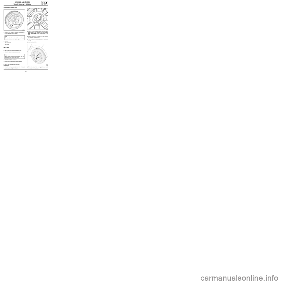
aStrike the inner surface of the wheel (2) using a mal-
let and a wooden block to detach it.
aRemove:
-the wheel bolts,
-the wheel.
REFITTING
I - REFITTING PREPARATION OPERATION
aClean the hub carrier using a wire brush.
aCheck the condition of the tyre.
aDo not move or remove the balance weights.
II - REFITTING OPERATION FOR PART
CONCERNED
aClean the mating surfaces between the wheel and
the hub carrier using a wire brush.aCoat the wheel-mating face (3) with COPPER ANTI-
SEIZE AGENT (see Vehicle: Parts and consum-
ables for the repair) (04B, Consumables - Prod-
ucts).
aAlign the mark on the wheel with the mark made on
the hub when it was removed.
aFit the wheel to the vehicle, positioning the valve at
the top.
aInsert the wheel bolts.
aTighten the wheel bolts to bring all the bolt heads
into contact with the wheel.
106089
Note:
Do not strike the surface of the wheel using
excessive force as this may damage it.
Note:
there are two types of wheel bolts for alloy and
steel wheel rims; do not swap them.
124750
113180
Page 148 of 281
35A-8
WHEELS AND TYRES
Tyres: Removal - Refitting
35A
REMOVAL
I - REMOVAL PREPARATION OPERATION
aPosition the vehicle on a two-post lift (see Vehicle:
Towing and lifting) (02A, Lifting equipment).
aRemove:
-the wheel in question (see 35A, Wheels and tyres,
Wheel: Removal - Refitting, page 35A-1) ,
-the balance weights,
-the valve mechanism.
II - OPERATION FOR REMOVAL OF PART
CONCERNED
aDetach:
-the bead from the outside of the tyre, starting with
the side opposite the valve,
-the bead from the inside of the tyre.aPosition the tyre lever approximately 15 cm from the
valve on the outside of the wheel rim in order to re-
move the exterior bead from the tyre.
aRemove the exterior bead of the tyre, finishing at the
valve.
aPosition the tyre lever approximately 15 cm from the
valve on the outside of the wheel rim in order to re-
move the bead from inside the tyre.
aRemove the interior bead of the tyre, finishing at the
valve.
REFITTING
I - REFITTING PREPARATION OPERATION
aparts always to be replaced: Tyre valve
aLubricate the two tyre beads correctly using the
TYRE PASTE (see Vehicle: Parts and consum-
ables for the repair) (04B, Consumables - Prod-
ucts).
II - REFITTING OPERATION FOR PART
CONCERNED
aEngage the lower tyre bead approximately 15 cm af-
ter the valve.
aFinish fitting the tyre at the valve.
aFit the exterior bead approximately 15 cm after the
valve using the tyre lever.
aInflate the tyre to 3.5 bar to press the tyre beads
against the wheel rim.
18884
18885