air RENAULT TWINGO 2009 2.G Chasiss Service Manual
[x] Cancel search | Manufacturer: RENAULT, Model Year: 2009, Model line: TWINGO, Model: RENAULT TWINGO 2009 2.GPages: 281
Page 199 of 281
37A-20
MECHANICAL COMPONENT CONTROLS
Brake servo: Removal - Refitting
RIGHT-HAND DRIVE
37A
aDrain the refrigerant circuit using a refrigerant
charging station (see Refrigerant circuit: Drain-
ing - Filling) (62A, Air conditioning).
aRemove the "dehydrator reservoir - expansion
valve" connecting pipe (see Dehydrator reservoir -
expansion valve connecting pipe: Removal - Re-
fitting) (62A, Air conditioning).
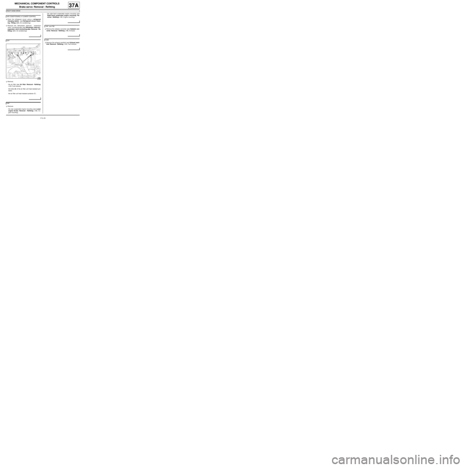
aRemove:
-the air filter (see Air filter: Removal - Refitting)
(12A, Fuel mixture),
-the bolts (6) of the air filter unit heat-resistant pro-
tector,
-the air filter unit heat-resistant protector (7) .
aRemove:
-the rear suspended engine mounting (see Lower
engine tie-bar: Removal - Refitting) (19D, En-
gine mounting),-the right-hand suspended engine mounting (see
Right-hand suspended engine mounting: Re-
moval - Refitting) (19D, Engine mounting).
aRemove the catalytic converter (see Catalytic con-
verter: Removal - Refitting) (19B, Exhaust).
aRemove the exhaust manifold (see Exhaust mani-
fold: Removal - Refitting) (12A, Fuel mixture). AIR CONDITIONING or CLIMATE CONTROL
D7F
123868
D4F
D4F, and 780
K4M
Page 202 of 281
37A-23
MECHANICAL COMPONENT CONTROLS
Brake servo: Removal - Refitting
RIGHT-HAND DRIVE
37A
II - REFITTING OPERATION FOR PART
CONCERNED
aPosition the brake servo by moving the engine for-
ward as far as possible and tilting the pushrod up-
wards.
aRefit the brake servo from underneath the vehicle.
aRefit the brake servo.
aPosition the “brake - clutch pedal” assembly on the
bulkhead.
aTorque tighten the “brake - clutch pedal” assem-
bly nuts (21 Nm).
aRefit:
-the new dual safety connecting shaft between the
brake servo pushrod and the brake pedal from right
to left and from top to bottom,
-the brake servo nuts.
aTorque tighten the brake servo nuts (21 Nm).
III - FINAL OPERATION.
aRefit:
-the clutch master cylinder support,
-the clutch master cylinder support bolts,
-the clutch master cylinder rod on the clutch pedal.
aRefit the exhaust manifold (see Exhaust manifold:
Removal - Refitting) (12A, Fuel mixture).aRefit the catalytic converter (see Catalytic convert-
er: Removal - Refitting) (19B, Exhaust).
aRefit:
-the right-hand suspended engine mounting (see
Right-hand suspended engine mounting: Re-
moval - Refitting) (19D, Engine mounting),
-the rear suspended engine mounting (see Lower
engine tie-bar: Removal - Refitting) (19D, En-
gine mounting).
aRefit:
-the air filter box heat-resistant protector,
-the air filter box heat-resistant protector bolts,
-the air filter (see Air filter: Removal - Refitting)
(12A, Fuel mixture).
aRefit the "dehydrator reservoir - expansion valve"
connection (see Dehydrator reservoir - expansion
valve connecting pipe: Removal - Refitting) (62A,
Air conditioning).
aFill the refrigerant circuit using a refrigerant charg-
ing station (see Refrigerant circuit: Draining -
Filling) (62A, Air conditioning).
aRefit the ignition coil (see Coils: Removal - Refit-
ting) (17A, Ignition). D4F
K4M
JH3 or JR5
K4M
D4F, and 780
D4F
D7F
AIR CONDITIONING or CLIMATE CONTROL
D4F or D7F
Page 204 of 281
37A-25
MECHANICAL COMPONENT CONTROLS
Vacuum pump: Removal - Refitting
K9K
37A
REMOVAL
I - REMOVAL PREPARATION OPERATION
aRemove:
-the engine cover,
-the air filter unit (see Air filter unit: Removal - Re-
fitting) (MR 411, 12A, Fuel mixture).
II - OPERATION FOR REMOVAL OF PART
CONCERNED
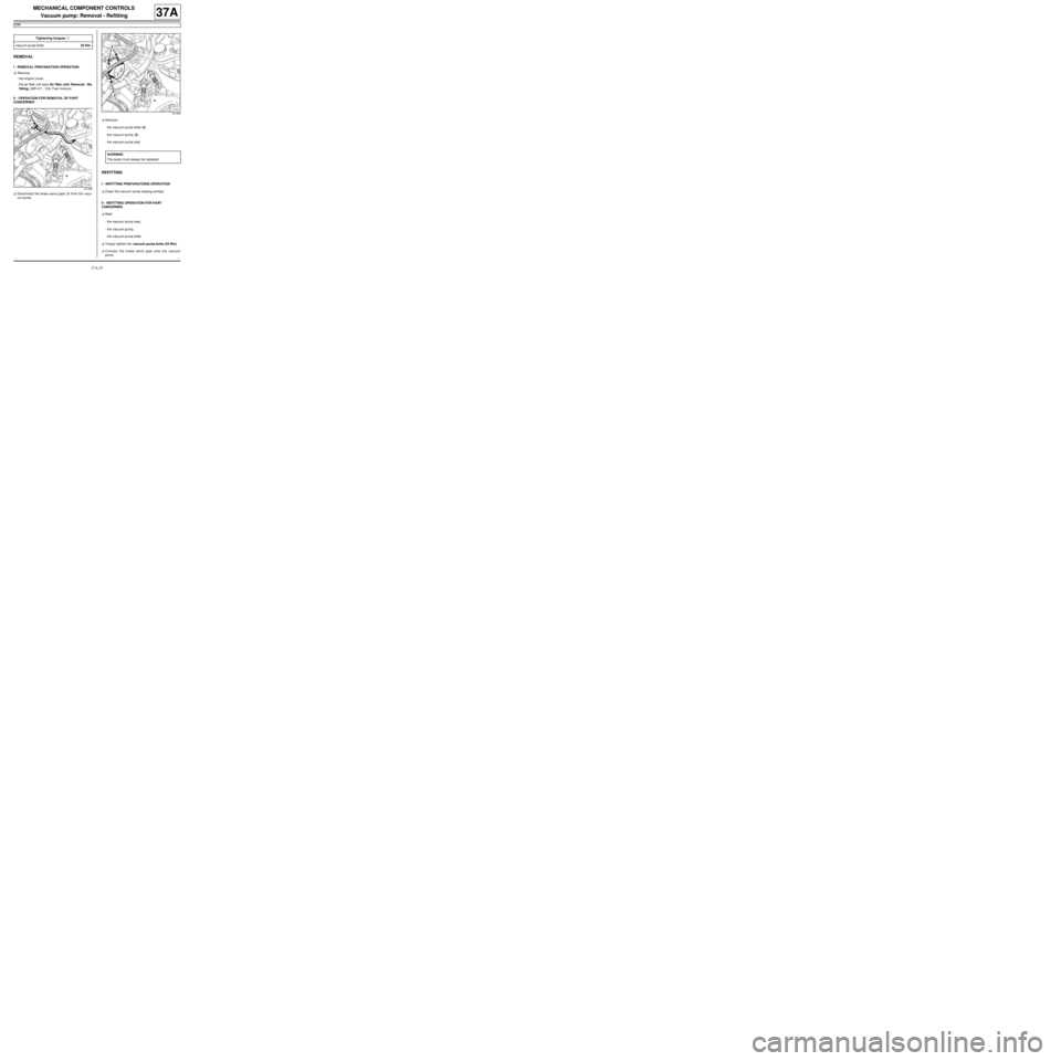
aDisconnect the brake servo pipe (1) from the vacu-
um pump.aRemove:
-the vacuum pump bolts (2) ,
-the vacuum pump (3) ,
-the vacuum pump seal.
REFITTING
I - REFITTING PREPARATIONS OPERATION
aClean the vacuum pump sealing surface.
II - REFITTING OPERATION FOR PART
CONCERNED
aRefit:
-the vacuum pump seal,
-the vacuum pump,
-the vacuum pump bolts.
aTorque tighten the vacuum pump bolts (25 Nm).
aConnect the brake servo pipe onto the vacuum
pump. Tightening torquesm
vacuum pump bolts25 Nm
121356
121355
WARNING
The seals m ust always be replaced.
Page 205 of 281

37A-26
MECHANICAL COMPONENT CONTROLS
Vacuum pump: Removal - Refitting
K9K
37A
III - FINAL OPERATION.
aRefit:
-the air filter unit (see Air filter unit: Removal - Re-
fitting) (MR 411, 12A, Fuel mixture),
-the engine cover.
Page 208 of 281
37A-29
MECHANICAL COMPONENT CONTROLS
Accelerator pedal: Removal - Refitting
37A
REMOVAL
I - REMOVAL OPERATION FOR ALUMINIUM
PEDAL PAD
aHeat the pedal pad with a heat stripper to a maxi-
mum temperature of 80˚C.
aRemove the pad using a pair of pliers.
aClean the residue of adhesive on the pedal (see
Tools for stripping very thick soft mastic: Use) .
II - OPERATION FOR REMOVAL OF PART
CONCERNED
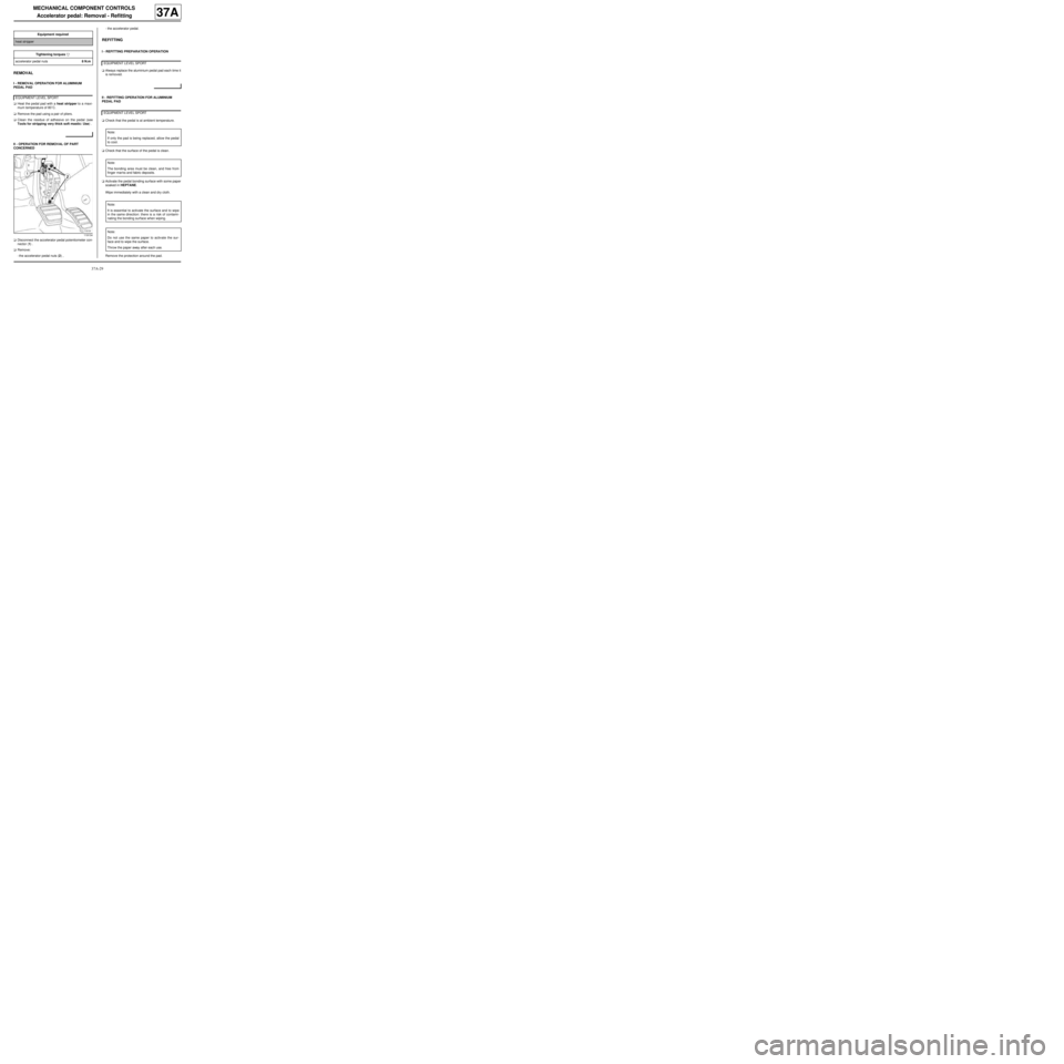
aDisconnect the accelerator pedal potentiometer con-
nector (1) .
aRemove:
-the accelerator pedal nuts (2) ,-the accelerator pedal.
REFITTING
I - REFITTING PREPARATION OPERATION
aAlways replace the aluminium pedal pad each time it
is removed.
II - REFITTING OPERATION FOR ALUMINIUM
PEDAL PAD
aCheck that the pedal is at ambient temperature.
aCheck that the surface of the pedal is clean.
aActivate the pedal bonding surface with some paper
soaked in HEPTANE.
Wipe immediately with a clean and dry cloth.
Remove the protection around the pad. Equipment required
heat str ipper
Tightening torquesm
accelerator pedal nuts8 N.m
EQ UIPMENT LEVEL SPORT
119134
EQUIPMENT LEVEL SPORT
EQUIPMENT LEVEL SPORT
Note:
If only the pad is being replaced, allow the pedal
to cool.
Note:
The bonding area must be clean, and free from
finger mar ks and fabric deposits.
Note:
It is essential to activate the surface and to wipe
in the same direction: there is a risk of contami-
nating the bonding surface when wiping.
Note:
Do not use the same paper to activate the sur-
face and to wipe the surface.
Throw the paper away after each use.
Page 210 of 281
37A-31
MECHANICAL COMPONENT CONTROLS
Brake pedal: Removal - Refitting
RIGHT-HAND DRIVE, and 5-SPEED MANUAL GEARBOX
37A
REMOVAL
I - REMOVAL PREPARATION OPERATION
aRemove:
-the dashboard lower trim (1) ,
-the brake pedal switch (see 37A, Mechanical
component controls, Brake pedal switch: Re-
moval - Refitting, page 37A-42) .
aRemove the accelerator pedal (see 37A, Mechani-
cal component controls, Accelerator pedal: Re-
moval - Refitting, page 37A-29) .aRemove the clutch pedal switch (see ) .
aRemove the dashboard side face (2) .
aDisconnect the airbag inhibitor switch connector (3) . Equipment required
heat str ipper
Tightening torquesm
bolts of the « brake -
clutch pedal assembly » 21 N.m
123870
JB1
CRUISE CONTROL
123870
123871
Page 211 of 281
37A-32
MECHANICAL COMPONENT CONTROLS
Brake pedal: Removal - Refitting
RIGHT-HAND DRIVE, and 5-SPEED MANUAL GEARBOX
37A
aRemove:
-the clutch master cylinder rod (4) ,
-the nuts (5) from the clutch master cylinder sup-
port,
-the clutch master cylinder support (6) ,
-the connecting clip (7) between the outlet pipe and
the clutch master cylinder,
-the clutch master cylinder (8) .aRemove the dashboard bolts (9) .
aMove the dashboard away slightly.
II - REMOVAL OPERATION FOR THE ALUMINIUM
PEDAL PADS
aHeat the pedal pad with a heat stripper to a maxi-
mum temperature of 80˚C.
aRemove the pad using a pair of pliers.
aClean the residue of adhesive on the pedal (see
Tools for stripping very thick soft mastic: Use) . JH3 or JR5
123904
123871
EQUIPMENT LEVEL SPORT
Page 215 of 281
37A-36
MECHANICAL COMPONENT CONTROLS
Brake pedal: Removal - Refitting
RIGHT-HAND DRIVE, and 5-SPEED MANUAL GEARBOX
37A
aBond the pedal pad (19) to the pedal (20) by press-
ing on the right-hand side.
Press the pad to ensure bonding.
IV - FINAL OPERATION
aFit the dashboard.
aRefit the dashboard bolts.
aConnect the airbag inhibition switch connector.
aRefit the dashboard side panel.
aRefit:
-the clutch master cylinder,
-the connecting clip between the outlet pipe and the
clutch master cylinder,
-the clutch master cylinder support,
-the clutch support bolts,
-the clutch master cylinder rod.aRefit the clutch pedal switch (see ) .
aRefit the accelerator pedal (see 37A, Mechanical
component controls, Accelerator pedal: Remov-
al - Refitting, page 37A-29) .
aRefit:
-the brake pedal switch (see 37A, Mechanical
component controls, Brake pedal switch: Re-
moval - Refitting, page 37A-42) ,
-the dashboard lower trim.
135017
Note:
Respect the range of motion when fitting.
JH3 or JR5
CRUISE CONTROL
JB1
Page 218 of 281
37A-39
MECHANICAL COMPONENT CONTROLS
Brake pedal: Removal - Refitting
LEFT-HAND DRIVE, and 5-SPEED MANUAL GEARBOX
37A
REMOVAL
I - REMOVAL PREPARATION OPERATION
aMark the switch wiring routing on the pedals.
aUnclip the switch wiring from the pedal assembly.
aRemove the brake pedal switch (see 37A, Mechan-
ical component controls, Brake pedal switch:
Removal - Refitting, page 37A-42) .
aRemove the clutch pedal switch (see 37A, Mechan-
ical component controls, Clutch pedal switch:
Removal - Refitting, page 37A-52) .
II - REMOVAL OPERATION FOR THE ALUMINIUM
PEDAL PADS
aHeat the pedal pad with a heat stripper to a maxi-
mum temperature of 80˚C.
aRemove the pad using a pair of pliers.
aClean the residue of adhesive on the pedal (see
Tools for stripping very thick soft mastic: Use) .III - OPERATION FOR REMOVAL OF PART
CONCERNED
aRemove the connecting shaft (1) between the brake
pedal and the brake servo pushrod:
-unlock the shaft in accordance with (2) ,
-extract the shaft in accordance with (3) .
aUnclip the clutch master cylinder (4) . Equipment required
heat str ipper
Tightening torquesm
nuts on the « brake -
clutch pedal assembly » 25 N.m
CRUISE CONTROL
EQ UIPMENT LEVEL SPORT
128482
JH3 or JR5
121366
Page 227 of 281
37A-48
MECHANICAL COMPONENT CONTROLS
Parking brake lever: Adjustment
37A
A poorly adjusted parking brake:
-prevents correct operation of the automatic compen-
sation system for the brake shoes,
-causes premature wear of brake shoes.
ADJUSTMENT
I - ADJUSTMENT PREPARATION OPERATION
aPosition the vehicle on a two-post lift (see Vehicle:
Towing and lifting) .
aApply the parking brake five times to condition the
cables for normal use.
aPut the parking brake lever into the released posi-
tion.
aCheck that the rear wheels turn freely. If they do not,
check the following components and if necessary re-
pair:
-the parking brake cables,
-the calliper piston,
-the automatic compensation system,
-calliper
aRemove the rear wheels (see 35A, Wheels and ty-
res, Wheel: Removal - Refitting, page 35A-1) .
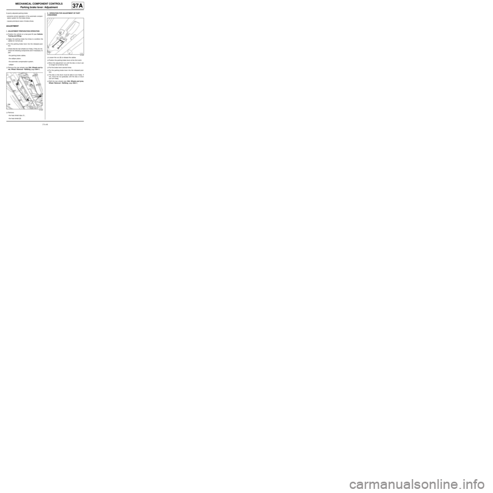
aRemove:
-the heat shield clips (1) ,
-the heat shield (2) .II - OPERATION FOR ADJUSTMENT OF PART
CONCERNED
aLoosen the nut (2) to release the cables.
aPosition the parking brake lever at the 2nd notch.
aMove the adjustment nut until the disc or drum can
no longer be turned by hand.
aPull the brake lever several times.
aPut the parking brake lever into the released posi-
tion.
aThe disc or the drum must be able to turn freely. If
not, move the nut gradually until the disc or drum
can turn freely.
aRefit the rear wheels (see 35A, Wheels and tyres,
Wheel: Removal - Refitting, page 35A-1) .
121325
121334