air RENAULT TWINGO 2009 2.G Chasiss Owner's Guide
[x] Cancel search | Manufacturer: RENAULT, Model Year: 2009, Model line: TWINGO, Model: RENAULT TWINGO 2009 2.GPages: 281
Page 153 of 281
36A-2
STEERING ASSEMBLY
Track rod: Removal - Refitting
36A
REMOVAL
I - REMOVAL PREPARATION OPERATION
aPosition the vehicle on a two-post lift (see Vehicle:
Towing and lifting) (02A, Lifting equipment).
aRemove the front wheel (see 35A, Wheels and ty-
res, Wheel: Removal - Refitting, page 35A-1) .
II - OPERATION FOR REMOVAL OF PART
CONCERNED
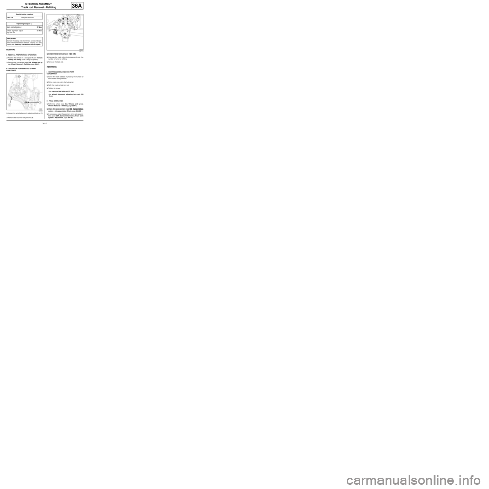
aLoosen the wheel alignment adjustment lock nut (1)
.
aRemove the track rod ball joint nut (2) .aExtract the ball joint using (3) (Tav. 476).
aUnscrew the track rod anti-clockwise and note the
number of turns for refitting.
aRemove the track rod.
REFITTING
I - REFITTING OPERATION FOR PART
CONCERNED
aScrew the track rod back in place by the number of
turns noted during removal.
aFit the track rod end in the hub carrier.
aRefit the track rod ball joint nut.
aTighten to torque:
-the track rod ball joint nut (37 N.m),
-the wheel alignment adjusting lock nut (53
N.m).
II - FINAL OPERATION
aRefit the wheel (see 35A, Wheels and tyres,
Wheel: Removal - Refitting, page 35A-1) .
aCheck the axle geometry (see 30A, General infor-
mation, Axle assemblies: Check, page 30A-23) .
aIf necessary, adjust the geometry of the axle assem-
blies (see 30A, General information, Front axle
system: Adjustment, page 30A-36) . Special tooling required
Tav. 476Ball joint extractor.
Tightening torquesm
track rod ball joint nut37 N.m
wheel alignment adjust-
ing lock nut53 N.m
IMPORTANT
Consult the safety and cleanliness advice and oper-
ation recommendations before carrying out any
repair (see Steering: Precautions for the repair) .
122722
122713
Page 155 of 281
36A-4
STEERING ASSEMBLY
Axial ball joint linkage: Removal - Refitting
36A
REMOVAL
I - REMOVAL PREPARATION OPERATION
aPosition the vehicle on a two-post lift ( (see Vehicle:
Towing and lifting) ).
a
aApply the before repair procedure using the dia-
gnostic tool:
-connect the diagnostic tool,
-select the airbag computer,
-go to repair mode,
-apply the "before repair procedure".
aRemove:
-the front wheel on the side in question (see 35A,
Wheels and tyres, Wheel: Removal - Refitting,
page 35A-1) ,
-the track rod (see 36A, Steering assembly, Track
rod: Removal - Refitting, page 36A-2) ,
-the steering box gaiter (see 36A, Steering assem-
bly, Steering box gaiter: Removal - Refitting,
page 36A-16) .
II - OPERATION FOR REMOVAL OF PART
CONCERNED
aLock the wheels to disengage the rod teeth on the
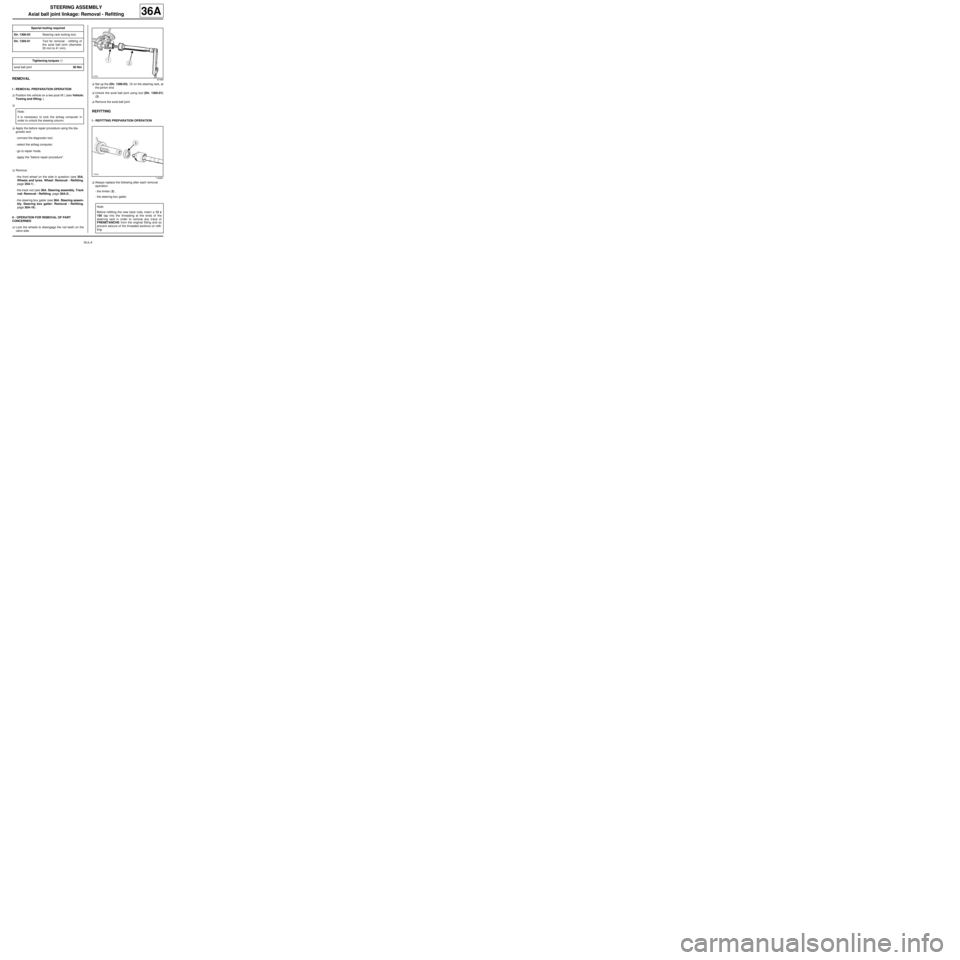
valve side.aSet up the (Dir. 1306-03) (1) on the steering rack, at
the pinion end.
aUnlock the axial ball joint using tool (Dir. 1305-01)
(2) .
aRemove the axial ball joint.
REFITTING
I - REFITTING PREPARATION OPERATION
aAlways replace the following after each removal
operation:
-the limiter (3) ,
-the steering box gaiter. Special tooling required
Dir. 1306-03Steering r ack locking tool.
Dir. 1305-01Tool for removal - refitting of
the axial ball joint (diameter
35 mm to 41 mm).
Tightening torquesm
axial ball joint50 Nm
Note:
It is necessary to lock the airbag computer in
order to unlock the steering column.
97469
116991
Note:
Before refitting the new track rods, inser t a 12 x
100 tap into the threading at the ends of the
steer ing rack in order to remove any trace of
FRENETANCHE from the original fitting and so
pre vent seizure of the threaded sections on refit-
ting.
Page 156 of 281
36A-5
STEERING ASSEMBLY
Axial ball joint linkage: Removal - Refitting
36A
II - REFITTING OPERATION FOR PART
CONCERNED
aRefit on the steering rack:
-the limiter,
-the axial ball joint whose threading has been coat-
ed with HIGH RESISTANCE THREAD LOCK.
aTorque tighten the axial ball joint (50 Nm) using the
(Dir. 1305-01) (2) .
aRemove the (Dir. 1306-03) (1) from the steering
rack on the pinion end.
III - FINAL OPERATION
aRefit:
-the steering box gaiter (see 36A, Steering assem-
bly, Steering box gaiter: Removal - Refitting,
page 36A-16) ,
-the track rod (see 36A, Steering assembly, Track
rod: Removal - Refitting, page 36A-2) ,
-the front wheel on the side in question (see 35A,
Wheels and tyres, Wheel: Removal - Refitting,
page 35A-1) .
a
aApply the before repair procedure using the dia-
gnostic tool:
-connect the diagnostic tool,
-select the airbag computer,
-go to repair mode,
-apply the "after repair procedure".
aCheck the settings of the axle assemblies (see 30A,
General information, Front axle system: Adjust-
ment, page 30A-36) .
aIf necessary, adjust the geometry of the axle assem-
blies (see 30A, General information, Front axle
system: Adjustment, page 30A-36) . Note:
It is necessary to unlock the airbag computer in
order to lock the steering column.
Page 158 of 281
36A-7
STEERING ASSEMBLY
Steering column: Removal - Refitting
LEFT-HAND DRIVE
36A
REMOVAL
I - REMOVAL PREPARATION OPERATION
aUnlock the steering column.
aLock the airbag computer using the Diagnostic tool
(see Fault finding - Replacement of components)
(MR 413, 88C, Airbags - Pretensioners).
aDisconnect the battery (see Battery: Removal - Re-
fitting) (MR 411, 80A, Battery).
aSet the wheels straight ahead.
aRemove:
-the driver's front airbag (see Driver's frontal air-
bag: Removal - Refitting) (MR 411, 88C, Airbags
- Pretensioners),
-the steering wheel (see 36A, Steering assembly,
Steering wheel: Removal - Refitting, page 36A-
23) ,-the steering column switch assembly (see Steer-
ing column switch assembly: Removal - Refit-
ting) (MR 411, 84A, Steering column switch
assembly),
-the immobiliser antenna/transponder ring (see
Transponder ring: Removal - Refitting) (MR
411, 82A, Immobiliser),
-the ignition switch if the steering column is replaced
(see Ignition switch: Removal - Refitting) (MR
411, 82A, Immobiliser).
II - REMOVAL OPERATION FOR PART
CONCERNED
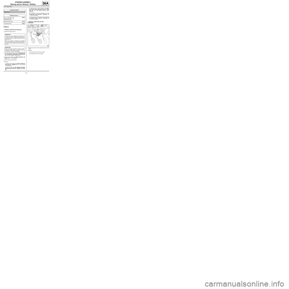
aRemove the cover from the universal joint (1) (do not
keep).
aRemove:
-the universal joint bolt (2) (do not keep),
-the universal joint nut (do not keep). Equipment required
Diagnostic tool
Tightening torquesm
bolt connecting the
steering column to the
inter mediate shaft30 Nm
steer ing column bolts21 Nm
universal joint bolt24 Nm
IMPORTANT
To avoid any risk of triggering when working on
or near a pyrotechnic component (airbags or pre-
tensioners), lock the airbag computer using the
diagnostic tool.
When this function is activated, all the trigger
lines are inhibited and the airbag warning light on
the instrument panel lights up continuously (igni-
tion on).
IMPORTANT
Never handle the pyrotechnic systems (preten-
sioners or airbags) near to a source of heat or
naked flame - they may be triggered.
119544
Page 161 of 281
36A-10
STEERING ASSEMBLY
Steering column: Removal - Refitting
LEFT-HAND DRIVE
36A
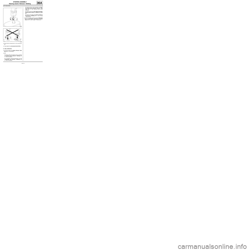
aCheck that the universal joint is in the correct posi-
tion.
aTorque tighten the universal joint bolt (24 Nm).
III - FINAL OPERATION.
aConnect the battery (see Battery: Removal - Refit-
ting) (MR 411, 80A, Battery).
aRefit:
-the ignition switch if the steering column is replaced
(see Ignition switch: Removal - Refitting) (MR
411, 82A, Immobiliser),
-the immobiliser antenna/transponder ring (see
Transponder ring: Removal - Refitting) (MR
411, 82A, Immobiliser),-the steering column switch assembly (see Steer-
ing column switch assembly: Removal - Refit-
ting) (MR 411, 84A, Steering column switch
assembly),
-the steering wheel (see 36A, Steering assembly,
Steering wheel: Removal - Refitting, page 36A-
23) ,
-the driver's front airbag (see Driver's frontal air-
bag: Removal - Refitting) (MR 411, 88C, Airbags
- Pretensioners).
aUnlock the airbag computer using the Diagnostic
tool (see Fault finding - Replacement of compo-
nents) (MR 413, 88C, Airbags - Pretensioners).
116021
116022
Page 162 of 281
36A-11
STEERING ASSEMBLY
Steering column: Removal - Refitting
RIGHT-HAND DRIVE
36A
REMOVAL
I - REMOVAL PREPARATION OPERATION
aUnlock the steering column.
a
Lock the airbag computer using the Diagnostic tool
(see Fault finding - Replacement of components)
(MR 413, 88C, Airbags and seat belt pretensioners).
aDisconnect the battery (see Battery: Removal - Re-
fitting) (MR 411, 80A, Battery).
aRemove:
-the driver's front airbag (see Driver's frontal air-
bag: Removal - Refitting) (MR 411, 88C, Airbags
and pretensioners),
-the steering wheel (see 36A, Steering assembly,
Steering wheel: Removal - Refitting, page 36A-
23) .aRemove the rev counter (see Rev counter: Remov-
al - Refitting) (MR 411, 83A, Instrument panel).
aRemove:
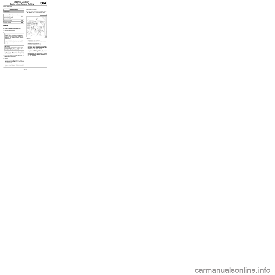
-the dashboard lower cover (1) ,
-the bolts (2) from the steering wheel lower cover,
-the steering wheel lower cover (3) ,
-the steering wheel upper cover (4) ,
-the steering column switch assembly (see Steer-
ing column switch assembly: Removal - Refit-
ting) (MR 411, 84A, Control - Signals),
-the antenna/transponder ring (see Transponder
ring: Removal - Refitting) (MR 411, 82A, Immobi-
liser),
-the ignition switch if the steering column is replaced
(see Ignition switch: Removal - Refitting) (MR
411, 82A, Immobiliser). Equipment required
Diagnostic tool
Tightening torquesm
bolt connecting the
steer ing column and the
inter mediate shaft30 Nm
steer ing column bolts21 Nm
universal joint bolt24 Nm
IMPORTANT
To avoid any risk of triggering when working on
or near a pyrotechnic component (airbags or pre-
tensioners), lock the airbag computer using the
diagnostic tool.
When this function is activated, all the trigger
lines are inhibited and the airbag warning light on
the instrument panel lights up continuously (igni-
tion on).
IMPORTANT
Never handle the pyrotechnic systems (preten-
sioners or airbags) near to a source of heat or
naked flame - they may be triggered.
ENGINE REV COUNTER
123870
Page 166 of 281
36A-15
STEERING ASSEMBLY
Steering column: Removal - Refitting
RIGHT-HAND DRIVE
36A
-the steering wheel lower cover,
-the steering wheel lower cover bolts,
-the dashboard lower cover.
aRefit the rev counter (see Rev counter: Removal -
Refitting) (MR 411, 83A, Instrument panel).
aRefit:
-the steering wheel (see 36A, Steering assembly,
Steering wheel: Removal - Refitting, page 36A-
23) ,
-the driver's front airbag (see Driver's frontal air-
bag: Removal - Refitting) (MR 411, 88C, Airbags
and pretensioners).
aConnect the battery (see Battery: Removal - Refit-
ting) (MR 411, 80A, Battery).
a
Unlock the airbag computer using the Diagnostic
tool (see Fault finding - Replacement of compo-
nents) (MR 413, 88C, Airbags and pretensioners). ENGINE REV COUNTER
IMPORTANT
To avoid a fault with or even triggering of pyro-
technic components (airbags or pretensioners),
check the airbag computer using the diagnostic
tool.
Page 167 of 281
36A-16
STEERING ASSEMBLY
Steering box gaiter: Removal - Refitting
36A
REMOVAL
I - REMOVAL PREPARATION OPERATION
aPosition the vehicle on a two-post lift (see Vehicle:
Towing and lifting) (02A, Lifting equipment).
aRemove:
-the front wheel (see 35A, Wheels and tyres,
Wheel: Removal - Refitting, page 35A-1) ,
-the track rod, (see 36A, Steering assembly,
Track rod: Removal - Refitting, page 36A-2)
-the wheel alignment adjusting lock nut.
II - OPERATION FOR REMOVAL OF PART
CONCERNED
a
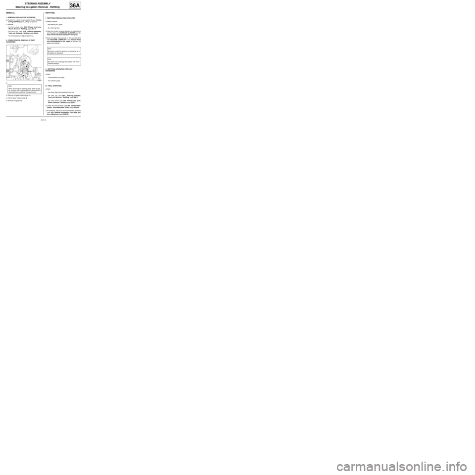
aRemove the gaiter retaining clip (1)
aCut the gaiter retaining clip (2) .
aRemove the gaiter (3) .
REFITTING
I - REFITTING PREPARATION OPERATION
aAlways replace:
-the steering box gaiter,
-the retaining clips.
aClean the contact surfaces between the steering box
and the gaiter using SURFACE CLEANER (see Ve-
hicle: Parts and consumables for the repair) .
aCoat the gaiter bearing face on the axial ball joint
with SILICONE LUBRICANT (see Vehicle: Parts
and consumables for the repair) to prevent the
gaiter from twisting.
II - REFITTING OPERATION FOR PART
CONCERNED
aRefit:
-a new steering box gaiter,
-new retaining clips.
III - FINAL OPERATION.
aRefit:
-the wheel alignment adjustment lock nut,
-the track rod, (see 36A, Steering assembly,
Track rod: Removal - Refitting, page 36A-2)
-the front wheel (see 35A, Wheels and tyres,
Wheel: Removal - Refitting, page 35A-1) .
aCheck the axle geometry (see 30A, General infor-
mation, Axle assemblies: Check, page 30A-23) .
aIf necessary, adjust the axle assemblies' geometry
(see 30A, General information, Front axle sys-
tem: Adjustment, page 30A-36) .
105678
Note:
When removing the steering gaiter, blast the gai-
ter surfaces with compressed air to eliminate any
impurities that could enter the steering box.
Note:
Be sure to centre the steer ing to ensure the air in
the gaiters is equalised.
Note:
Be careful not to damage the gaiters: risk of irre-
versible damage.
Page 174 of 281
36A-23
STEERING ASSEMBLY
Steering wheel: Removal - Refitting
36A
REMOVAL
I - REMOVAL PREPARATION OPERATION
aApply the procedure for deactivating the safety sys-
tems. (see Airbag and pretensioners: Precau-
tions for the repair)
a
aRemove the driver's front airbag (see Driver's fron-
tal airbag: Removal - Refitting) .
aSet the wheels straight ahead.
aDisconnect the connectors.II - OPERATION FOR REMOVAL OF PART
CONCERNED
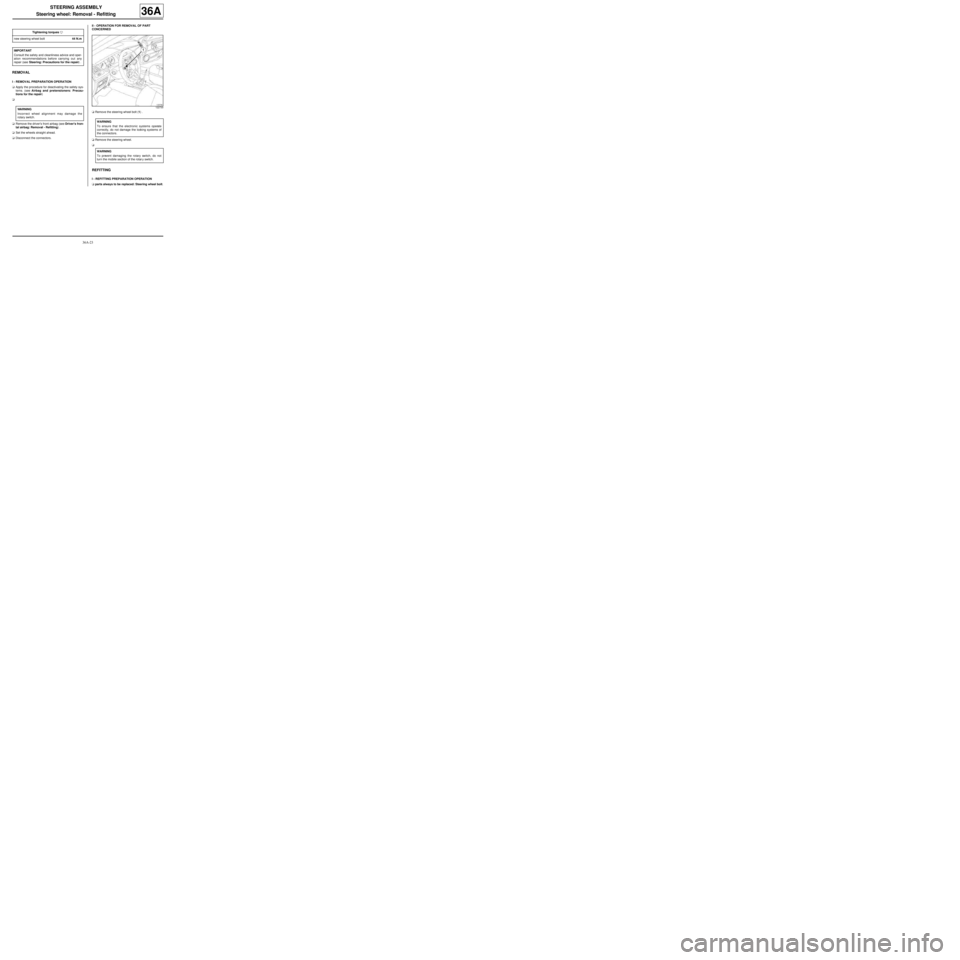
aRemove the steering wheel bolt (1) .
aRemove the steering wheel.
a
REFITTING
I - REFITTING PREPARATION OPERATION
aparts always to be replaced: Steering wheel bolt. Tightening torquesm
new steering wheel bolt44 N.m
IMPORTANT
Consult the safety and cleanliness advice and oper-
ation recommendations before carrying out any
repair (see Steering: Precautions for the repair) .
WARNING
Incorrect wheel alignment may damage the
rotary switch.
122730
WARNING
To ensure that the electronic systems operate
correctly, do not damage the locking systems of
the connectors.
WARNING
To prevent damaging the rotary switch, do not
turn the mobile section of the rotar y switch.
Page 175 of 281
36A-24
STEERING ASSEMBLY
Steering wheel: Removal - Refitting
36A
II - REFITTING OPERATION FOR PART
CONCERNED
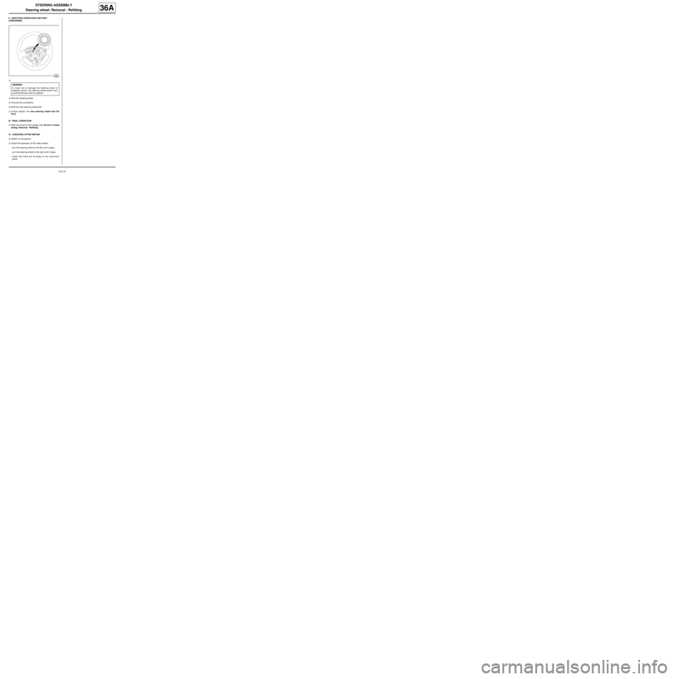
a
aRefit the steering wheel.
aConnect the connectors.
aRefit the new steering wheel bolt.
aTorque tighten the new steering wheel bolt (44
N.m).
III - FINAL OPERATION
aRefit the driver's front airbag (see Driver's frontal
airbag: Removal - Refitting) .
IV - CHECKING AFTER REPAIR
aSwitch on the ignition.
aCheck the operation of the rotary switch:
-turn the steering wheel to the left until it stops,
-turn the steering wheel to the right until it stops,
-check that there are no faults on the instrument
panel.
105327
WARNING
In order not to damage the steering wheel or
steering column, the steering wheel-column fool-
proofing devices must be aligned.