tow RENAULT TWINGO 2009 2.G Chasiss Repair Manual
[x] Cancel search | Manufacturer: RENAULT, Model Year: 2009, Model line: TWINGO, Model: RENAULT TWINGO 2009 2.GPages: 281
Page 180 of 281
37A-1
MECHANICAL COMPONENT CONTROLS
Master cylinder: Removal - Refitting
JB1 or JH1 or JH3 or JR5
37A
REMOVAL
I - REMOVAL PREPARATION OPERATION
aPosition the vehicle on a two-post lift (see Vehicle:
Towing and lifting) (02A, Lifting equipment).
aRemove:
-the battery (see Battery: Removal - Refitting)
(80A, Battery)
-the battery tray (see Battery tray: Removal - Re-
fitting) (80A, Battery).
aRemove:
-the injection computer (see Petrol injection com-
puter: Removal - Refitting) (17B, Petrol injection),
-the injection computer support.II - OPERATION FOR REMOVAL OF PART
CONCERNED
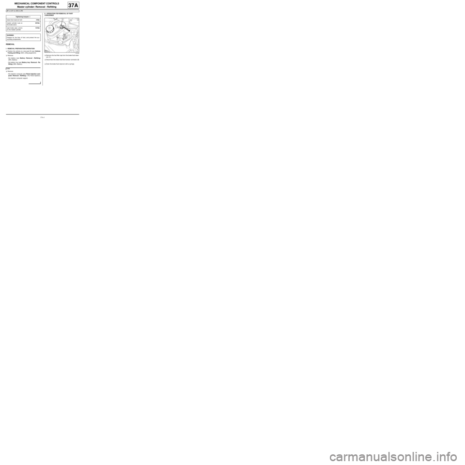
aRemove the fuel filler cap from the brake fluid reser-
voir (1) .
aDisconnect the brake fluid level sensor connector (2)
.
aDrain the brake fluid reservoir with a syringe. Tightening torquesm
brake fluid reservoir bolt4 Nm
master cylinder nuts on
the brake servo25 Nm
rigid brake pipe unions
on the master cylinder15 Nm
WARNING
Prepare for the flow of fluid, and protect the sur-
rounding components.
K4M
121344
Page 184 of 281
37A-5
MECHANICAL COMPONENT CONTROLS
Master cylinder: Removal - Refitting
RIGHT-HAND DRIVE
37A
REMOVAL
I - REMOVAL PREPARATION OPERATION
aPosition the vehicle on a two-post lift (see Vehicle:
Towing and lifting) (02A, Lifting equipment).
aRemove:
-the scuttle panel grille (see Scuttle panel grille:
Removal - Refitting) (56A, Exterior equipment),
-the scoop under the scuttle panel grille (see Scoop
under the scuttle panel grille: Removal - Refit-
ting) (56A, Exterior equipment).aRemove:
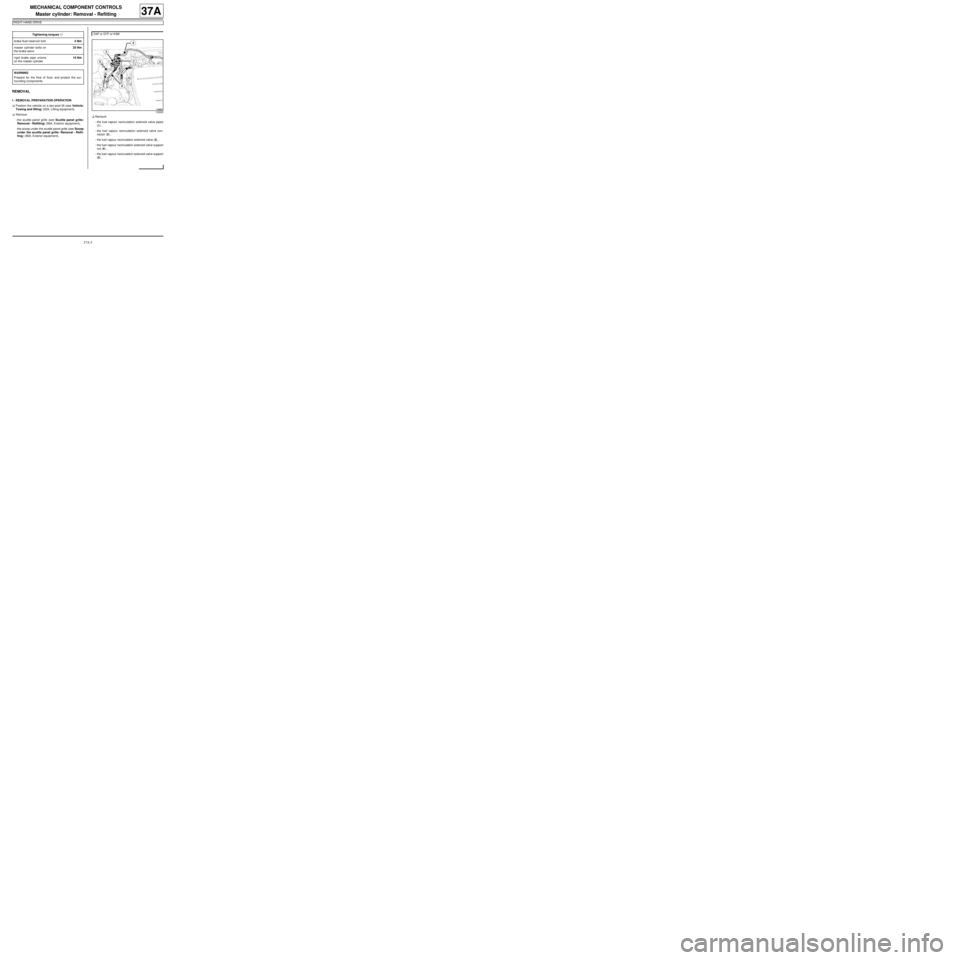
-the fuel vapour recirculation solenoid valve pipes
(1) ,
-the fuel vapour recirculation solenoid valve con-
nector (2) ,
-the fuel vapour recirculation solenoid valve (3) ,
-the fuel vapour recirculation solenoid valve support
nut (4) ,
-the fuel vapour recirculation solenoid valve support
(5) . Tightening torquesm
brake fluid reservoir bolt4 Nm
master cylinder bolts on
the brake servo25 Nm
rigid brake pipe unions
on the master cylinder15 Nm
WARNING
Prepare for the flow of fluid, and protect the sur-
rounding components.
D4F or D7F or K4M
123852
Page 190 of 281
37A-11
MECHANICAL COMPONENT CONTROLS
Brake servo non-return valve: Removal - Refitting
RIGHT-HAND DRIVE
37A
REMOVAL
I - REMOVAL PREPARATION OPERATION
aPosition the vehicle on a two-post lift (see Vehicle:
Towing and lifting) (MR 411, 02A, Lifting equip-
ment).
aRemove:
-the front right-hand wheel (see 35A, Wheels and
tyres, Wheel: Removal - Refitting, page 35A-1) ,
-the front right-hand wheel arch liner (see Front
wheel arch liner: Removal - Refitting) (MR 412,
55A, Exterior protection),
-the scuttle panel grille (see Scuttle panel grille:
Removal - Refitting) (MR 412, 56A, Exterior
equipment),
-the scoop under the scuttle panel grille (see Scoop
under the scuttle panel grille: Removal - Refit-
ting) (MR 412, 56A, Exterior equipment).
aRemove:
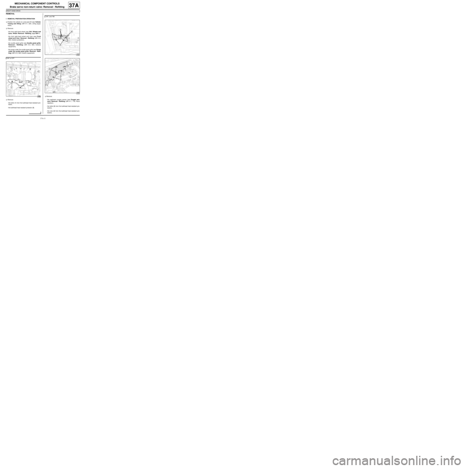
-the bolts (1) from the bulkhead heat-resistant pro-
tector,
-the bulkhead heat-resistant protector (2) .aRemove:
-the upstream oxygen sensor (see Oxygen sen-
sors: Removal - Refitting) (MR 411, 17B, Petrol
injection),
-the bolts (3) from the bulkhead heat-resistant pro-
tectors,
-the nuts (4) from the bulkhead heat-resistant pro-
tectors, D4F or D7F
123866
D4F, and 780
123903
123908
Page 193 of 281
37A-14
MECHANICAL COMPONENT CONTROLS
Brake servo: Removal - Refitting
JB1 or JH1 or JH3 or JR5, and LEFT-HAND DRIVE
37A
REMOVAL
I - REMOVAL PREPARATION OPERATION
aPosition the vehicle on a two-post lift (see Vehicle:
Towing and lifting) (02A, Lifting equipment).
aRemove the battery (see Battery: Removal - Refit-
ting) (80A, Battery).
aRemove the gearbox computer (see Sequential
gearbox converter: Removal - Refitting) (21B,
Sequential gearbox).
aRemove the battery tray (see Battery tray: Remov-
al - Refitting) (80A, Battery).
aRemove the petrol injection computer (see Petrol
injection computer: Removal - Refitting) (17B,
Petrol injection).
aRemove the diesel injection computer (see Diesel
injection computer: Removal - Refitting) (13B,
Diesel injection).
aRemove:
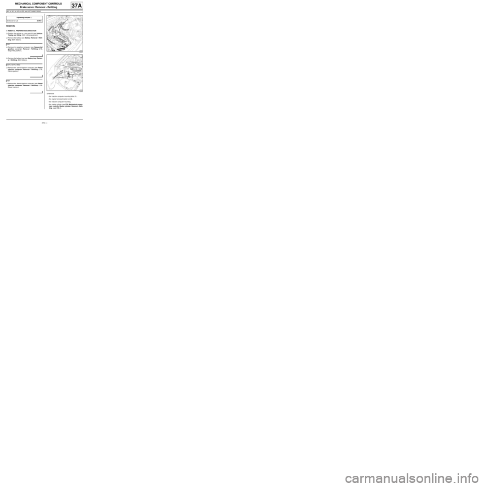
-the injection computer mounting bolts (1) ,
-the engine harness bracket nut (2) ,
-the injection computer mounting,
-the master cylinder (see 37A, Mechanical compo-
nent controls, Master cylinder: Removal - Refit-
ting, page 37A-1) . Tightening torquesm
brake servo nuts25 Nm
JH1
D4F or D7F or K4M
K9K
122323
122322
Page 198 of 281
37A-19
MECHANICAL COMPONENT CONTROLS
Brake servo: Removal - Refitting
RIGHT-HAND DRIVE
37A
REMOVAL
I - REMOVAL PREPARATION OPERATION
aPosition the vehicle on a two-post lift (see Vehicle:
Towing and lifting) (02A, Lifting equipment).
aRemove:
-the front right-hand wheel (see 35A, Wheels and
tyres, Wheel: Removal - Refitting, page 35A-1) ,
-the front right-hand wheel arch liner (see Front
wheel arch liner: Removal - Refitting) (55A, Ex-
terior protection),
-the scuttle panel grille (see Scuttle panel grille:
Removal - Refitting) (56A, Exterior equipment),
-the scoop under the scuttle panel grille (see Scoop
under the scuttle panel grille: Removal - Refit-
ting) (56A, Exterior equipment).aRemove:
-the fuel vapour recirculation solenoid valve pipes
(1) ,
-the fuel vapour recirculation solenoid valve con-
nector (2) ,
-the fuel vapour recirculation solenoid valve (3) ,
-the fuel vapour recirculation solenoid valve support
bolt (4) ,
-the fuel vapour recirculation solenoid valve support
(5) ,
-the brake master cylinder (see 37A, Mechanical
component controls, Master cylinder: Removal
- Refitting, page 37A-1) ,
-the brake servo non-return valve (see 37A, Me-
chanical component controls, Brake servo non-
return valve: Removal - Refitting, page 37A-11) .
aRemove the ignition coil (see Coils: Removal - Re-
fitting) (17A, Ignition). Special tooling required
Mot. 1672Low er engine support.
Equipment required
refrigerant charging station
Tightening torquesm
“brake - clutch pedal”
assembly nuts21 Nm
brake servo nuts21 Nm
123852
D4F or D7F
Page 225 of 281
37A-46
MECHANICAL COMPONENT CONTROLS
Parking brake lever: Removal - Refitting
37A
REMOVAL
I - REMOVAL PREPARATION OPERATION
aPosition the vehicle on a two-post lift (see Vehicle:
Towing and lifting) (MR 411, 02A, Lifting equip-
ment).
aRelease the parking brake lever.
aRemove:
-the heat shield clips (1) ,
-the heat shield (2) .aRemove the parking brake lever adjusting nut (3) .
aDetach the parking brake cables from the compen-
sator.
aRemove:
-the parking brake lever compensator (4) ,
-the front seats, completely (see Complete front
seat: Removal - Refitting) (MR 412 Bodywork,
75A, Front seat frames and runners).
aDepending on the equipment level, remove:
-the rear bench seatback (see Rear bench seat-
back: Removal - Refitting) (MR 412 Bodywork,
76A, Rear seat frames and runners),
-the rear bench seat base (see Rear bench seat
base: Removal - Refitting) (MR 412 Bodywork,
76A, Rear seat frames and runners)
-the rear seats, completely (see Complete rear
seat: Removal - Refitting) (MR 412 Bodywork,
76A, Rear seat frames and runners).
aPartially remove the floor carpet to access the park-
ing brake lever (see Floor carpet: Removal - Refit-
ting) (MR 412 Bodywork, 71A, Body internal trim). Tightening torquesm
par king brake lever nuts8 Nm
121325
121334
Page 227 of 281
37A-48
MECHANICAL COMPONENT CONTROLS
Parking brake lever: Adjustment
37A
A poorly adjusted parking brake:
-prevents correct operation of the automatic compen-
sation system for the brake shoes,
-causes premature wear of brake shoes.
ADJUSTMENT
I - ADJUSTMENT PREPARATION OPERATION
aPosition the vehicle on a two-post lift (see Vehicle:
Towing and lifting) .
aApply the parking brake five times to condition the
cables for normal use.
aPut the parking brake lever into the released posi-
tion.
aCheck that the rear wheels turn freely. If they do not,
check the following components and if necessary re-
pair:
-the parking brake cables,
-the calliper piston,
-the automatic compensation system,
-calliper
aRemove the rear wheels (see 35A, Wheels and ty-
res, Wheel: Removal - Refitting, page 35A-1) .
aRemove:
-the heat shield clips (1) ,
-the heat shield (2) .II - OPERATION FOR ADJUSTMENT OF PART
CONCERNED
aLoosen the nut (2) to release the cables.
aPosition the parking brake lever at the 2nd notch.
aMove the adjustment nut until the disc or drum can
no longer be turned by hand.
aPull the brake lever several times.
aPut the parking brake lever into the released posi-
tion.
aThe disc or the drum must be able to turn freely. If
not, move the nut gradually until the disc or drum
can turn freely.
aRefit the rear wheels (see 35A, Wheels and tyres,
Wheel: Removal - Refitting, page 35A-1) .
121325
121334
Page 233 of 281
37A-54
MECHANICAL COMPONENT CONTROLS
Clutch circuit: Bleed
JH3 or JR5
37A
Bleed in the event of:
-dead travel,
-pedal at mid-travel,
-pedal to the floor,
-poor gear changing.
I - PRECAUTIONS DURING REPAIR
Risks relating to contamination.
aThe hydraulic clutch system is very sensitive to con-
tamination. The risks caused by contamination are:
-impossible to change gears,
-damage to or destruction of the clutch system,
-leaks on the hydraulic circuit.
All the operations on the hydraulic clutch circuit sys-
tem must be carried out under excellent cleanliness
conditions. This ensures that no impurities enter the
hydraulic circuit during the operation.
The cleanliness principles apply to all components
of the hydraulic clutch circuit.
Items causing contamination are:
-metal or plastic swarf,
-fibres:
•cardboard,
•brushes,
•paper,
•clothing,
•cloth,
•dust and particles in the air,
•etc.
Cleaning cloths.
aUse lint-free cleaning cloths (see Products recom-
mended for the repair) (04B, Consumables - Prod-
ucts).
Each cloth must only be used once.There are two types of equipment used to bleed the
clutch circuit:
aARC50 via the brake fluid reservoir.
aSyringe via the bleed hole located on the clutch
slave cylinder.
There are two procedures used to bleed the clutch
circuit:
aIf no parts of the hydraulic clutch circuit are remo-
ved:
-Carry out the bleed operation using the ARC50 via
the brake fluid reservoir or using a new syringe via
the bleed hole located on the clutch slave cylinder.
aIf no parts of the hydraulic clutch circuit are remo-
ved:
-Only carry out the bleed operation using a new sy-
ringe by injecting the brake fluid via the bleed hole
on the clutch slave cylinder.
Consumables required for the repair:
aBleed the clutch circuit using approved (see Vehi-
cle: Parts and consumables for the repair) brake
fluid (04B, consumables - products).
II - PREPARATION OPERATION
aPosition the vehicle on a two-post lift (see Vehicle:
Towing and lifting) (02A, Lifting equipment).
aRemove the engine undertray. Equipment required
brake circuit bleeding device
hydraulic circuit bleed syringe
Note:
-Even the tiniest air bubble in the circuit can
cause faulty operation (pedal failing to return
properly, crunching sound when changing gear,
etc.).
-Incorrect bleeding can lead to incorrect detec-
tion of faults and unnecessary part replace-
ments.
Page 239 of 281
37A-60
MECHANICAL COMPONENT CONTROLS
Clutch circuit: Bleed
JH3 or JR5
37A
VI - FINAL OPERATION
aRefit the engine undertray.
aRemove the vehicle from the two-post lift (see Vehi-
cle: Towing and lifting) (02A, Lifting equipment).
Page 240 of 281
37A-61
MECHANICAL COMPONENT CONTROLS
Clutch master cylinder: Removal - Refitting
JH3
37A
REMOVAL
I - REMOVAL PREPARATION OPERATION
aPosition the vehicle on a two-post lift (see Vehicle:
Towing and lifting) (MR 411, 02A, Lifting equip-
ment).
aRemove:
-the front wheel on the driver's side (see 35A,
Wheels and tyres, Wheel: Removal - Refitting,
page 35A-1) ,
-the front wheel arch liner on the driver's side (see
Front wheel arch liner: Removal - Refitting) (MR
412, 55A, Exterior protection).
aUse a syringe to empty the brake fluid reservoir.
II - OPERATION FOR REMOVAL OF PART
CONCERNED
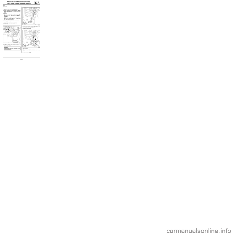
aUnclip the hydraulic clutch master cylinder rod (1)
from the clutch pedal.aDisconnect the brake fluid fuel supply pipe (2) from
the hydraulic clutch master cylinder.
aInsert the blanking plugs.
aPull the clip (2) .
aDetach the end (3) of the hydraulic clutch control
pipe.
aInsert the blanking plugs.
121366
WARNING
Prepare for the flow of fluid, and protect the sur-
rounding components.
121340
121341