Valve RENAULT TWINGO 2009 2.G Engine And Peripherals Workshop Manual
[x] Cancel search | Manufacturer: RENAULT, Model Year: 2009, Model line: TWINGO, Model: RENAULT TWINGO 2009 2.GPages: 652
Page 511 of 652
19A-1
COOLING
Engine cooling system: Specifications
D4F or D7F or K4M or K9K
19A
Vehicles in the current range have cooling systems
with the following basic specifications:
-hermetically-sealed pressurised circuit (with expan-
sion bottle valve),
-circuit using only type « D » fluid,
-passenger compartment heating system equipped
with a « heater matrix » type radiator located under
the dashboard which helps to cool the engine.
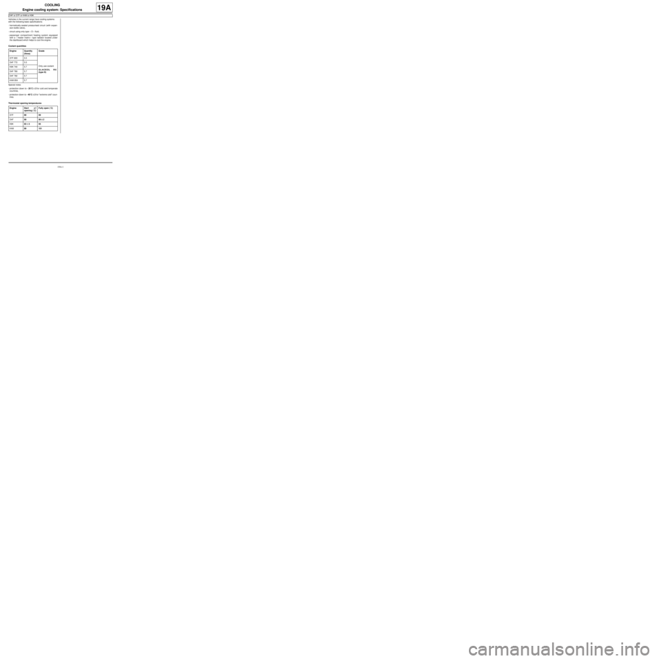
Coolant quantities
Special notes:
-protection down to - 25˚C ±± ± ±
2 for cold and temperate
countries,
-protection down to - 40˚C ±± ± ±
2 for "extreme cold" coun-
tries.
Thermostat opening temperaturesEngine Quantity
(litres)Grade
D7F 800 5.5
Only use coolant
GLACEOL RX
(type D) D4F 772 5.5
K9K 740 5.7
D4F 780 5.7
D4F 782 5.7
K4M 854 5.7
Engine Star t o f
opening (˚C)Fully open (˚C)
D7F89 99
D4F89 99 ±± ± ±
2
K9K83 ±± ± ±
395
K4M89 101
Page 512 of 652
19A-2
COOLING
Engine cooling system: Check
19A
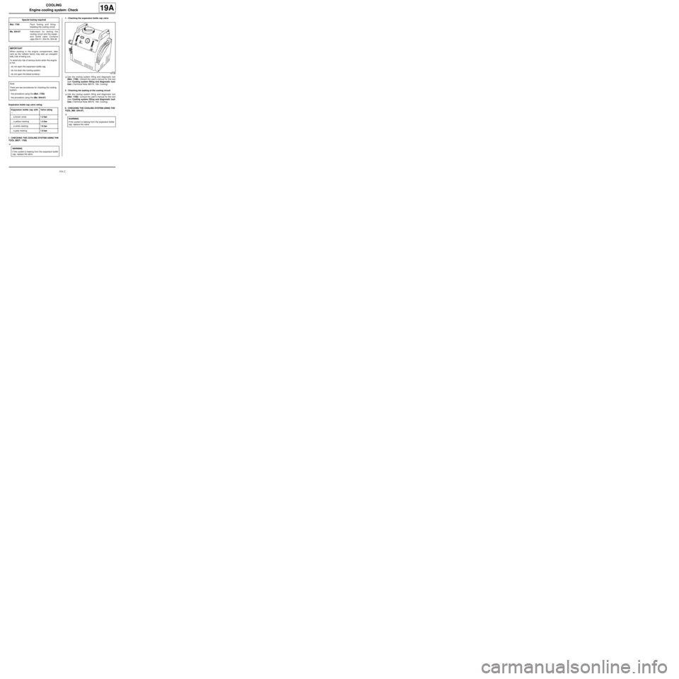
Expansion bottle cap valve rating:
I - CHECKING THE COOLING SYSTEM USING THE
TOOL (MOT. 1700)
a1 - Checking the expansion bottle cap valve
aUse the cooling system filling and diagnostic tool
(Mot. 1700). Consult the user's manual for this tool
(see Cooling system filling and diagnostic tool:
Use) (Technical Note 3857A, 19A, Cooling).
2 - Checking the sealing of the cooling circuit
aUse the cooling system filling and diagnostic tool
(Mot. 1700). Consult the user's manual for this tool
(see Cooling system filling and diagnostic tool:
Use) (Technical Note 3857A, 19A, Cooling).
II - CHECKING THE COOLING SYSTEM USING THE
TOOL (MS. 554-07)
a Special tooling required
Mot. 1700Fault finding and filling -
bleeding the cooling circuit.
Ms. 554-07Instr ument for testing the
cooling circuit and the expan-
sion bottle valve. Contains
caps 554-01, 554-04, 554-06
IMPORTANT
When working in the engine compartment, take
care as the radiator fan(s) may start up unexpect-
edly (risk of being cut).
To avoid any risk of serious burns when the engine
is hot:
-do not open the expansion bottle cap,
-do not drain the cooling system,
-do not open the bleed screw(s).
Note:
There are two procedures for checking the cooling
system:
-the procedure using the (Mot. 1700)
-the procedure using the (Ms. 554-07)
Expansion bottle cap with
...Valve rating
... a brown circle1.2 bar
... a yellow marking1.4 bar
... a white marking1.6 bar
... a grey marking1.8 bar
WARNING
If the coolant is leaking from the expansion bottle
cap, replace the valve.
107138
WARNING
If the coolant is leaking from the expansion bottle
cap, replace the valve.
Page 513 of 652
19A-3
COOLING
Engine cooling system: Check
19A
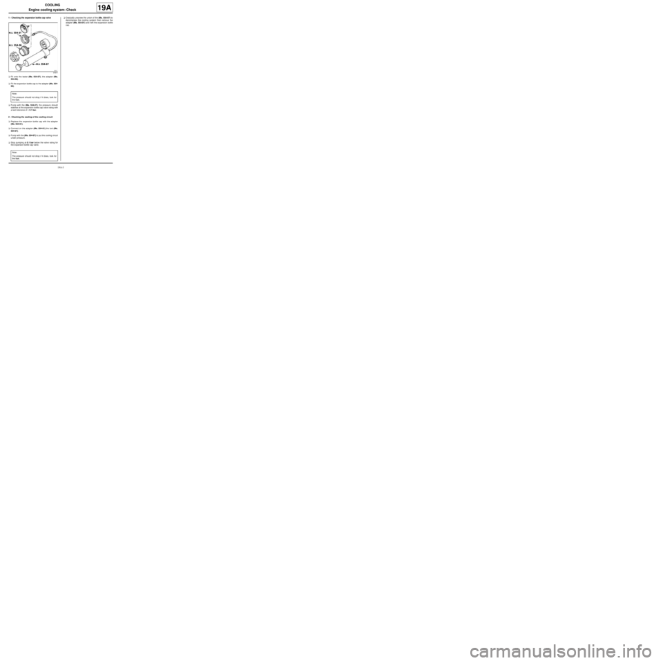
1 - Checking the expansion bottle cap valve
aFit onto the tester (Ms. 554-07), the adapter (Ms.
554-06).
aFit the expansion bottle cap to the adapter (Ms. 554-
06).
aPump with the (Ms. 554-07), the pressure should
stabilise at the expansion bottle cap valve rating with
a test tolerance of ± 0.1 bar.
2 - Checking the sealing of the cooling circuit
aReplace the expansion bottle cap with the adapter
(Ms. 554-01).
aConnect on the adapter (Ms. 554-01) the tool (Ms.
554-07).
aPump with the (Ms. 554-07) to put the cooling circuit
under pressure.
aStop pumping at 0.1 bar below the valve rating for
the expansion bottle cap valve.aGradually unscrew the union of the (Ms. 554-07) to
decompress the cooling system then remove the
adapter (Ms. 554-01) and refit the expansion bottle
cap.
97871
Note:
The pressure should not drop; if it does, look for
the leak.
Note:
The pressure should not drop; if it does, look for
the leak.
Page 515 of 652
19A-5
COOLING
Engine cooling system: Operating diagram
D4F, and 772 – D7F
19A
122038
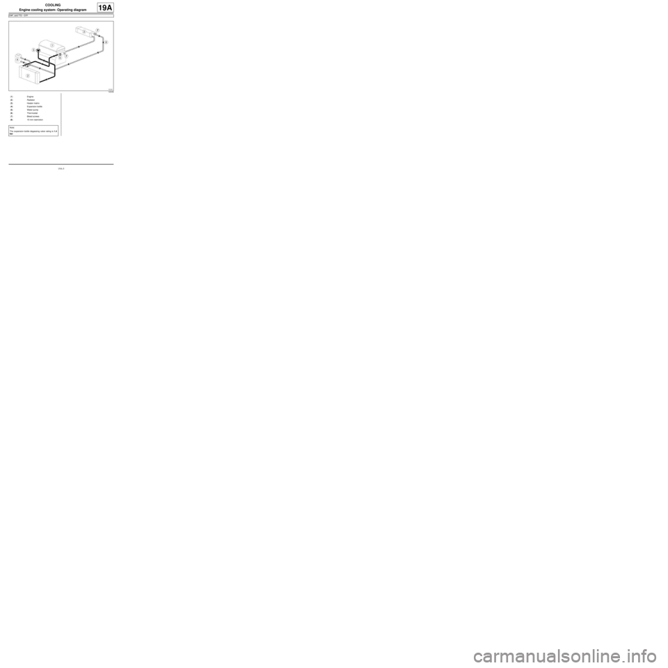
(1) Engine
(2) Radiator
(3) Heater matrix
(4) Expansion bottle
(5) Water pump
(6) Thermostat
(7) Bleed screws
(8) 10 mm restr iction
Note:
The expansion bottle degassing valve rating is 1.4
bar.
Page 516 of 652
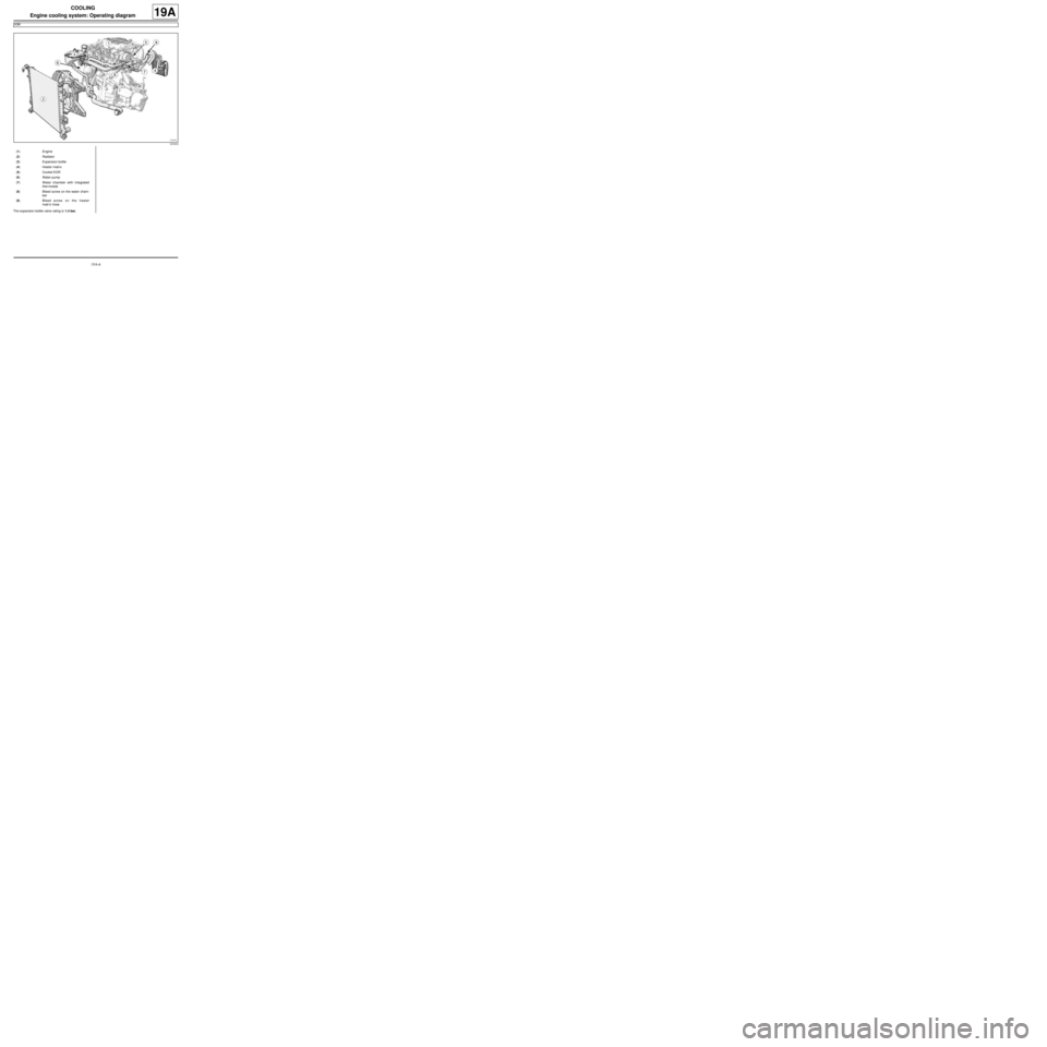
19A-6
COOLING
Engine cooling system: Operating diagram
K9K
19A
The expansion bottle valve rating is 1.4 bar.
121816
(1) Engine
(2) Radiator
(3) Expansion bottle
(4) Heater matrix
(5) Cooled EGR
(6) Water pump
(7) Water chamber with integrated
ther mostat
(8) Bleed screw on the water cham-
ber
(9) Bleed screw on the heater
matr ix hose
Page 517 of 652
19A-7
COOLING
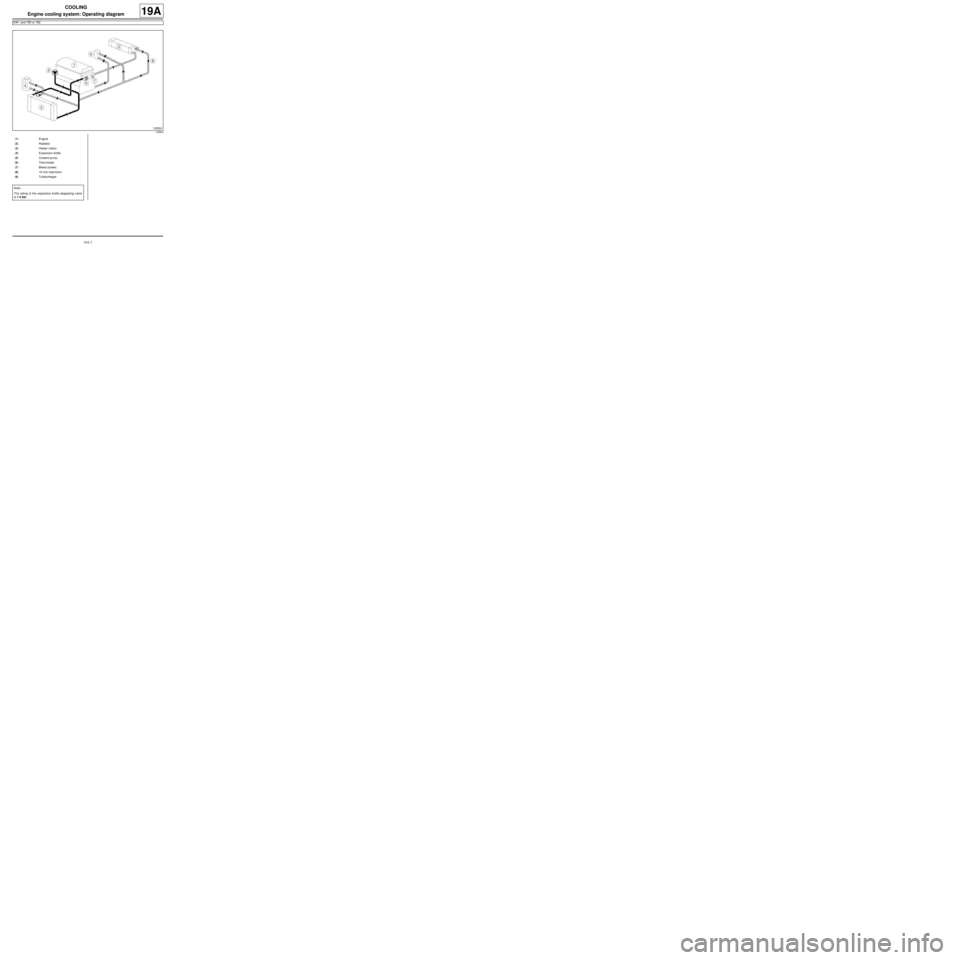
Engine cooling system: Operating diagram
D4F, and 780 or 782
19A
122824
(1) Engine
(2) Radiator
(3) Heater matrix
(4) Expansion bottle
(5) Coolant pump
(6) Thermostat
(7) Bleed screws
(8) 10 mm restr iction
(9) Turbocharger
Note:
The rating of the expansion bottle degassing valve
is 1.4 bar.
Page 519 of 652
19A-9
COOLING
Cooling system: Draining - Refilling
D4F or D7F or K4M or K9K
19A
a
I - DRAINING
aPosition the vehicle on a two-post lift (see Vehicle:
Towing and lifting) (02A, Lifting equipment).
aRemove the expansion bottle cap.aRemove the engine undertray.
aPosition the coolant recovery tray under the vehi-
cle.
aRemove the cooling radiator bottom hose clip using
the tool (Mot. 1202-01) or (Mot. 1202-02) or (Mot.
1448).
aOpen the cooling system by removing the cooling ra-
diator bottom hose using the tool (Car. 1363).
aUse a compressed air nozzle to blow air into the
system through the expansion bottle opening to re-
move as much coolant as possible.
II - CLEANING
aFill the cooling system with water through the expan-
sion bottle.
aLet the water run until the water collected by the
cooling radiator bottom hose becomes clear.
aUse a compressed air nozzle to blow air into the
circuit through the expansion bottle opening to re-
move as much water as possible.
aRefit the hose which was removed.
III - FILLING
a
1 - Filling procedure with the tool (Mot. 1700)
aFill the cooling system with engine coolant recom-
mended by the manufacturer (see Vehicle: Parts
and consumables for the repair) (04B, Consum-
ables - Products) using the tool (Mot. 1700).
For the use of this tool (see Cooling system filling
and diagnostic tool: Use) (NT 3857A, 19A, Cool-
ing). Special tooling required
Mot. 1202-01Clip pliers for hose clips
(large size).
Mot. 1202-02Clip pliers for hose clips
(small size)
Mot. 1448Remote operation pliers for
hose clips .
Car. 1363Set of tr im removal levers.
Mot. 1700Fault finding and filling -
bleeding the cooling circuit.
Ms. 554-07Instr ument for testing the
cooling circuit and the expan-
sion bottle valve. Contains
caps 554-01, 554-04, 554-06
Equipment required
coolant recovery tray
compressed air nozzle
pedal press
IMPORTANT
When working in the engine compartment, take
care as the radiator fan(s) may start up unex-
pectedly (risk of being cut).
To avoid any risk of serious burns when the
engine is hot:
-do not open the expansion bottle cap,
-do not dr ain the cooling system,
-do not open the bleed screw(s).
WARNING
Before the operation, protect the electrical acces-
sories to prevent any risk of short circuiting and
protect the belts to avoid damaging them.
K4M
Note:
There are two procedures for filling the cooling
system:
-the method using the (Mot. 1700) tool is recom-
mended by Renault. It saves a considerable
amount of time because it does not require the
cooling system bleed screws to be opened,
-the procedure without a special tool.
Page 530 of 652
19A-20
COOLING
Cooling radiator: Removal - Refitting
K4M
19A
REMOVAL
I - REMOVAL PREPARATION OPERATION
aPosition the vehicle on a two-post lift (see Vehicle:
Towing and lifting) (02A, Lifting equipment).
aDisconnect the battery (see Battery: Removal - Re-
fitting) (80A, Battery).
aDrain the air conditioning circuit using a refrigerant
charging station (see Refrigerant circuit: Drain-
ing - Filling) (62A, Air conditioning).
aRemove:
-the engine undertray bolts,
-the engine undertray,
-the front wheels (see Wheel: Removal - Refitting)
(35A, Wheels and tyres),
-the front wheel arch liners (see Front wheel arch
liner: Removal - Refitting) (55A, Exterior protec-
tion),
-the front bumper (see Front bumper: Removal -
Refitting) (55A, Exterior protection).
aDrain the cooling system (see 19A, Cooling, Cool-
ing system: Draining - Refilling, page 19A-9) . Special tooling required
Mot. 1448Remote operation pliers for
hose clips .
Equipment required
refrigerant charging station
safety strap(s)
Tightening torquesm
bolt of the dehydrator
reservoir - « expansion
valve connecting pipe » 8 N.m
compressor - con-
denser « connecting
pipe bolt » 8 N.m
air conditioning connect-
ing pipe bolts8 N.m
IMPORTANT
When working in the engine compartment, take
care as the radiator fan(s) may start up unexpect-
edly (risk of being cut).
To avoid any risk of serious burns when the engine
is hot:
-do not open the expansion bottle cap,
-do not drain the cooling system,
-do not open the bleed screw(s).
WARNING
Prepare for the flow of fluid, and protect the sur-
rounding components.
WARNING
When carr ying out a repair that requires a complete
change, it is essential to flush the circuit with clean
water, blast compressed air through the circuit to
drive out the water, fill and bleed the circuit and
then measure the effective protection.
The cr iteria to be met are:
-protection down to -25˚C ±± ± ±
2 for cold and temper-
ate countries,
-protection down to -40˚C ±± ± ±
2 for "extreme cold"
countries.
Page 531 of 652
19A-21
COOLING
Cooling radiator: Removal - Refitting
K4M
19A
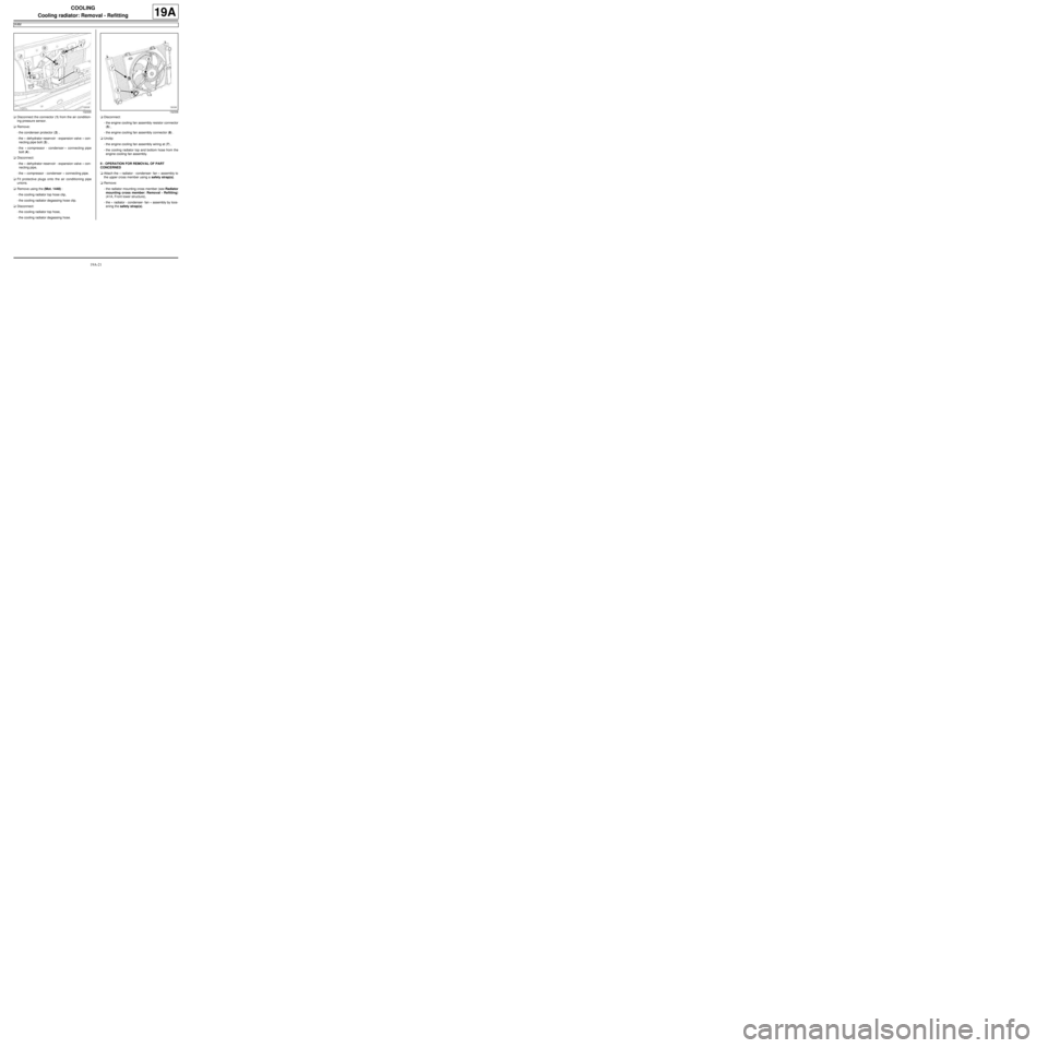
aDisconnect the connector (1) from the air condition-
ing pressure sensor.
aRemove:
-the condenser protector (2) ,
-the « dehydrator reservoir - expansion valve » con-
necting pipe bolt (3) ,
-the « compressor - condenser » connecting pipe
bolt (4) .
aDisconnect:
-the « dehydrator reservoir - expansion valve » con-
necting pipe,
-the « compressor - condenser » connecting pipe.
aFit protective plugs onto the air conditioning pipe
unions.
aRemove using the (Mot. 1448) :
-the cooling radiator top hose clip,
-the cooling radiator degassing hose clip.
aDisconnect:
-the cooling radiator top hose,
-the cooling radiator degassing hose.aDisconnect:
-the engine cooling fan assembly resistor connector
(5) ,
-the engine cooling fan assembly connector (6) .
aUnclip:
-the engine cooling fan assembly wiring at (7) ,
-the cooling radiator top and bottom hose from the
engine cooling fan assembly.
II - OPERATION FOR REMOVAL OF PART
CONCERNED
aAttach the « radiator - condenser- fan » assembly to
the upper cross member using a safety strap(s).
aRemove:
-the radiator mounting cross member (see Radiator
mounting cross member: Removal - Refitting)
(41A, Front lower structure),
-the « radiator - condenser- fan » assembly by loos-
ening the safety strap(s).
132335132336
Page 532 of 652
19A-22
COOLING
Cooling radiator: Removal - Refitting
K4M
19A
On the workbench
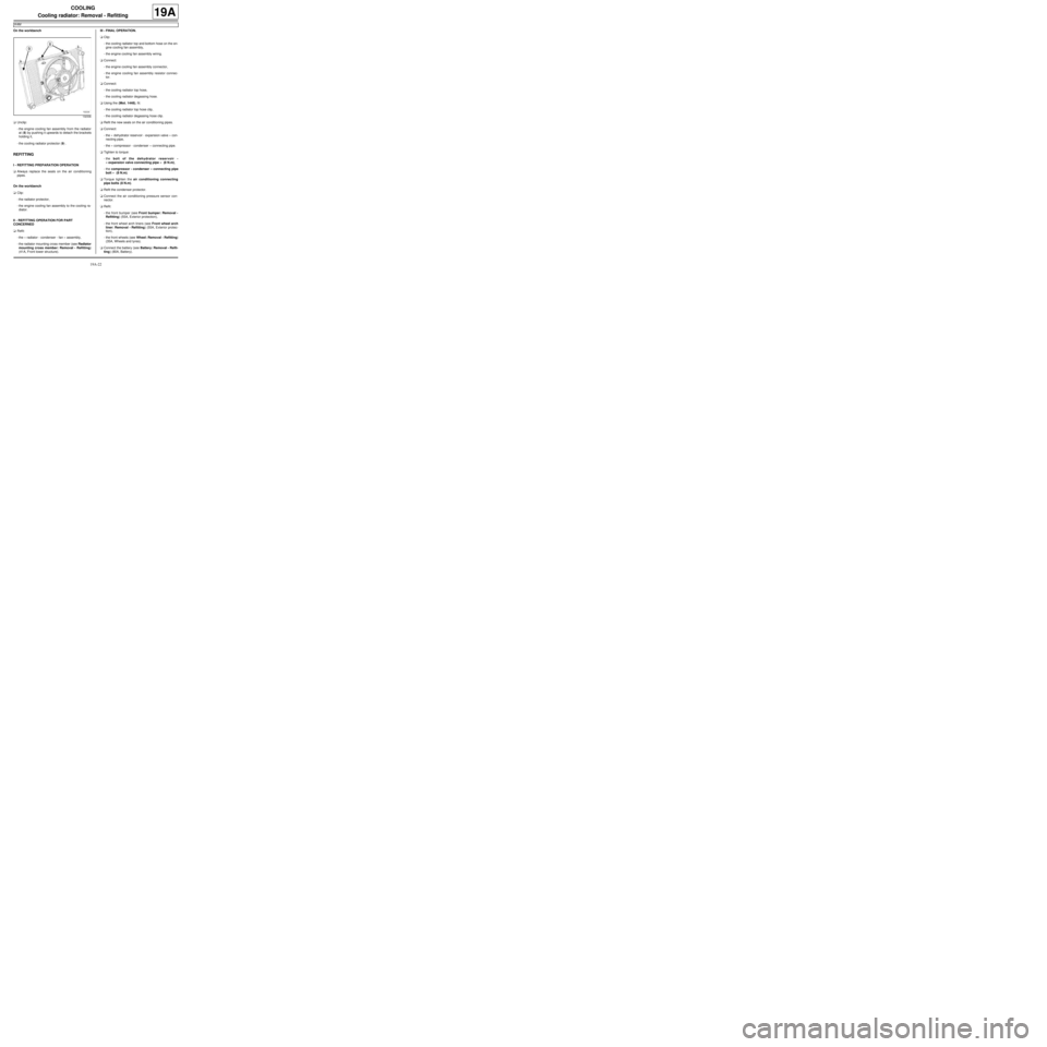
aUnclip:
-the engine cooling fan assembly from the radiator
at (8) by pushing it upwards to detach the brackets
holding it,
-the cooling radiator protector (9) .
REFITTING
I - REFITTING PREPARATION OPERATION
aAlways replace the seals on the air conditioning
pipes.
On the workbench
aClip:
-the radiator protector,
-the engine cooling fan assembly to the cooling ra-
diator.
II - REFITTING OPERATION FOR PART
CONCERNED
aRefit:
-the « radiator - condenser - fan » assembly,
-the radiator mounting cross member (see Radiator
mounting cross member: Removal - Refitting)
(41A, Front lower structure).III - FINAL OPERATION.
aClip:
-the cooling radiator top and bottom hose on the en-
gine cooling fan assembly,
-the engine cooling fan assembly wiring.
aConnect:
-the engine cooling fan assembly connector,
-the engine cooling fan assembly resistor connec-
tor.
aConnect:
-the cooling radiator top hose,
-the cooling radiator degassing hose.
aUsing the (Mot. 1448), fit:
-the cooling radiator top hose clip,
-the cooling radiator degassing hose clip.
aRefit the new seals on the air conditioning pipes.
aConnect:
-the « dehydrator reservoir - expansion valve » con-
necting pipe,
-the « compressor - condenser » connecting pipe.
aTighten to torque:
-the bolt of the dehydrator reservoir -
« expansion valve connecting pipe » (8 N.m),
-the compressor - condenser « connecting pipe
bolt » (8 N.m).
aTorque tighten the air conditioning connecting
pipe bolts (8 N.m).
aRefit the condenser protector.
aConnect the air conditioning pressure sensor con-
nector.
aRefit:
-the front bumper (see Front bumper: Removal -
Refitting) (55A, Exterior protection),
-the front wheel arch liners (see Front wheel arch
liner: Removal - Refitting) (55A, Exterior protec-
tion),
-the front wheels (see Wheel: Removal - Refitting)
(35A, Wheels and tyres).
aConnect the battery (see Battery: Removal - Refit-
ting) (80A, Battery).
132336