Valve RENAULT TWINGO 2009 2.G Engine And Peripherals Manual Online
[x] Cancel search | Manufacturer: RENAULT, Model Year: 2009, Model line: TWINGO, Model: RENAULT TWINGO 2009 2.GPages: 652
Page 344 of 652
13A-1
FUEL SUPPLY
Diesel supply circuit: Operating diagram
K9K
13A
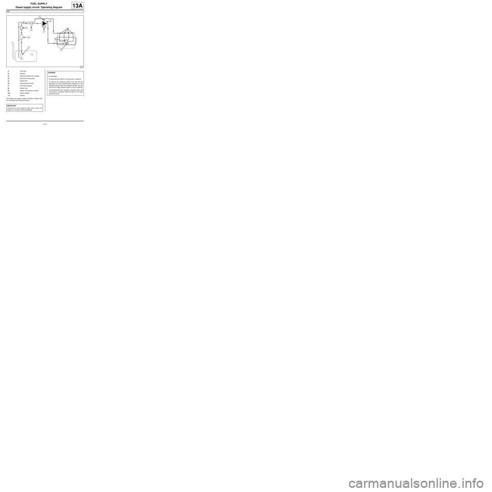
The diesel fuel supply system includes a diesel injec-
tion computer and various sensors.
120417
(1) Fuel tank
(2) Dipstick
(3) Electrical diesel fuel reheater
(4) Man ual priming pump
(5) Diesel filter
(6) High pressure pump
(7) Fuel fl ow actuator
(8) Injector rail
(9) Injector rail pressure sensor
(10) Diesel injector
(11) Venturi
IMPORTANT
Loosening a high pressure pipe union when the
engine is running is strictly prohibited.
WARNING
It is forbidden:
-to dismantle the interior of the pump or injectors.
-to remove the pressure sensor from the fuel rail
(because of circuit contamination problems). If the
pressure sensor fails, the pressure sensor, the rail
and the five high pressure pipes must be replaced,
-to dismantle the flow regulator solenoid valve and
the pressure regulator solenoid valve on the high
pressure pump.
Page 370 of 652
13B-9
DIESEL INJECTION
Diesel injection: List and location of components
K9K, and 740
13B
121436
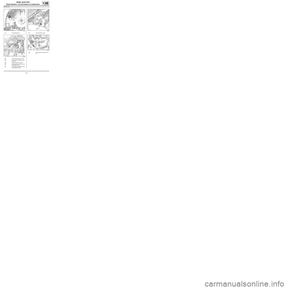
(11) Pre-postheating unit
120039
(12) Turbocharging pressure sensor
(13) Exhaust gas recirculation sole-
noid valve
(14) Coolant temper ature sensor
(15) Turbocharger upstream inlet air
temperature sensor
(16) Turbocharger downstream inlet
air temperature sensor
120326
(17) Cylinder position sensor
120327
(18) Engine speed and position sen-
sor
Page 372 of 652
13B-11
DIESEL INJECTION
Diesel injection: List and location of components
K9K, and 718
13B
141220
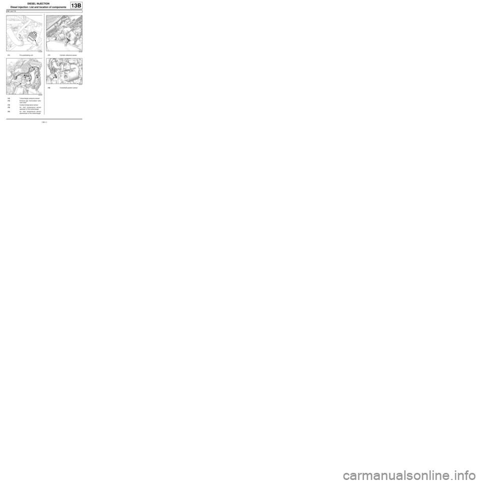
(11) Pre-postheating unit
120039
(12) Turbocharger pressure sensor
(13) Exhaust gas recirculation sole-
noid valve
(14) Coolant temper ature sensor
(15) Air inlet temperature sensor
upstream of the turbocharger
(16) Air inlet temperature sensor
downstream of the turbocharger
120326
(17) Cylinder reference sensor
120327
(18) Crankshaft position sensor
Page 373 of 652
13B-12
DIESEL INJECTION
Diesel injection: List and location of components
K9K, and 718
13B
122830
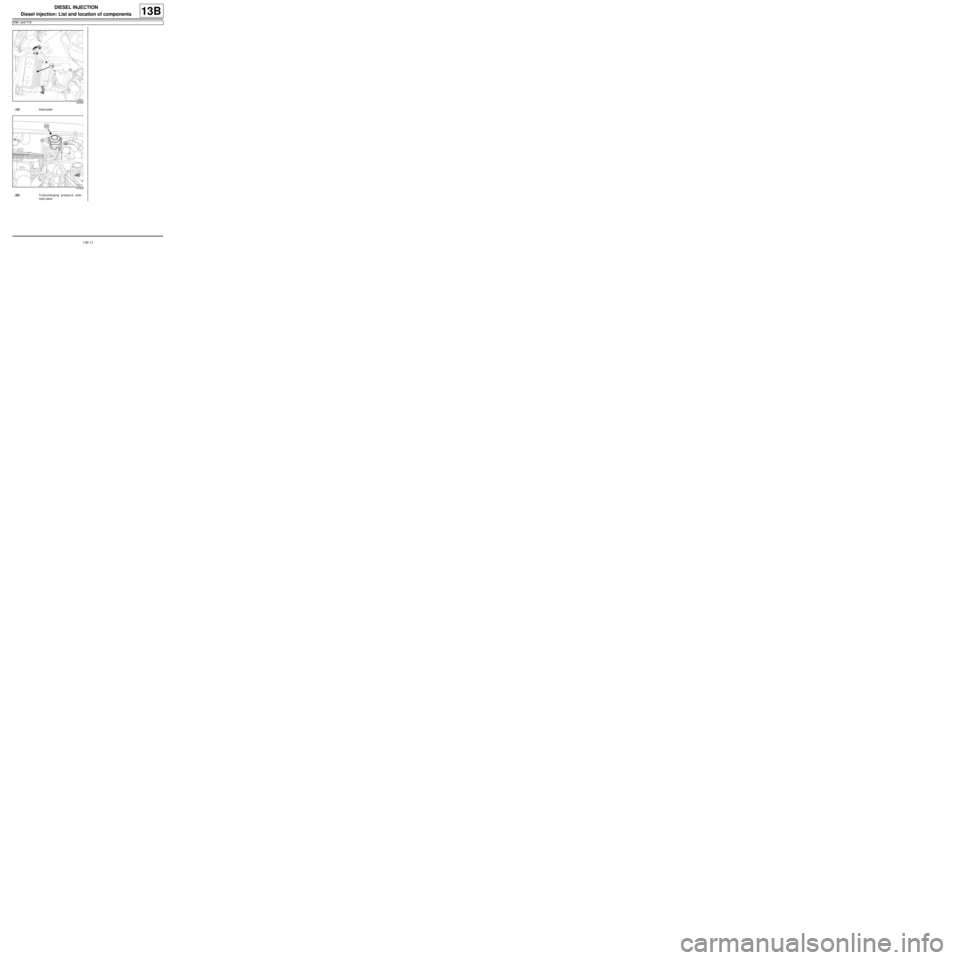
(19) Intercooler
141219
(20) Turbocharging pressure sole-
noid valve
Page 419 of 652
14A-1
ANTIPOLLUTION
Oil vapour rebreathing circuit: Descriptions
K9K
14A
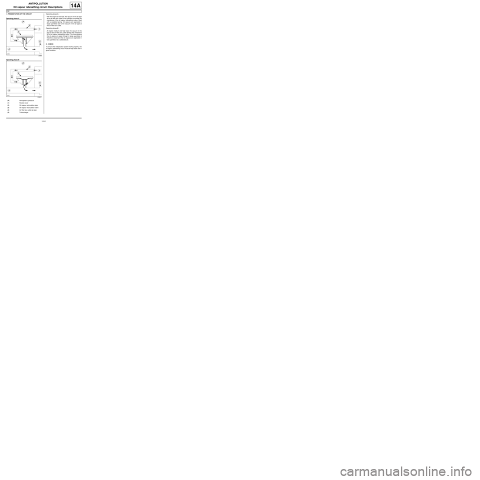
I - PRESENTATION OF THE CIRCUIT
Operating phase A
Operating phase BOperating phase A :
-with the engine at low load, the vacuum in the air pipe
at the air filter box outlet is not sufficient to activate the
membrane of the oil vapour rebreathing valve, fitted
with a weighted spring. Oil vapours are aspirated in
large quantities due to the vacuum in the air pipe at
the air filter box outlet.
Operating phase B :
-At engine medium and high load, the vacuum in the
pipe at the air filter box outlet attracts the membrane
of the oil vapour rebreathing valve. The hole allowing
the oil vapours to pass through in large quantities is
therefore closed and the oil vapours are aspirated in
low quantities via a calibrated jet.
II - CHECK
To ensure the antipollution system works properly, the
oil vapour rebreathing circuit must be kept clean and in
good condition.
20965
20965-1
(P) Atmospher ic pressure
(1) Rocker cover
(2) Oil vapour recirculation pipe
(3) Oil vapour recirculation valve
(4) Air filter box outlet air pipe
(5) Turbocharger
Page 420 of 652
14A-2
ANTIPOLLUTION
Fuel vapour recirculation circuit: Operating diagram
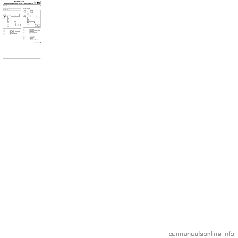
D4F or D7F
14A
D4F, and 772 – D7F
97393-1
(1) Inlet distributor
(2) Fuel vapour absorber bleed
solenoid valve
(3) Petrol vapour absorber
(4) Tank
(5) Fresh air vent
D4F, and 780 or 782
121923
(1) Inlet distributor
(2) Fuel vapour absorber bleed
solenoid valve
(3) Petrol vapour absorber
(4) Tank
(5) Fresh air vent
(6) Anti-retur n valve
(7) Turbocharger
(8) Air filter unit
(9) Air filter box air outlet pipe
Page 421 of 652
14A-3
ANTIPOLLUTION
Fuel vapour recirculation circuit: Check
D4F or D7F
14A
I - CHECKING THE OPERATION OF THE FUEL
VAPOUR ABSORBER BLEED
aCheck the condition of the pipes to the tank.aCheck the condition of the pipes to the tank.
II - FUEL VAPOUR ABSORBER BLEED
CONDITIONS
aThe fuel vapour absorber bleed solenoid valve is
controlled by the computer.
During « on board diagnostic » fault finding, fuel va-
pour absorber bleeding is not authorised.
The opening cyclic ratio of the fuel vapour absorber
bleed solenoid valve can be viewed on the Diagnos-
tic tool by reading parameter « Fuel vapour absorb-
er bleed solenoid valve OCR » .
The solenoid valve is closed for a value below 1.2%. Equipment required
Diagnostic tool
Note:
Incorrect operation of the system may result in
rough idle or engine stalling.
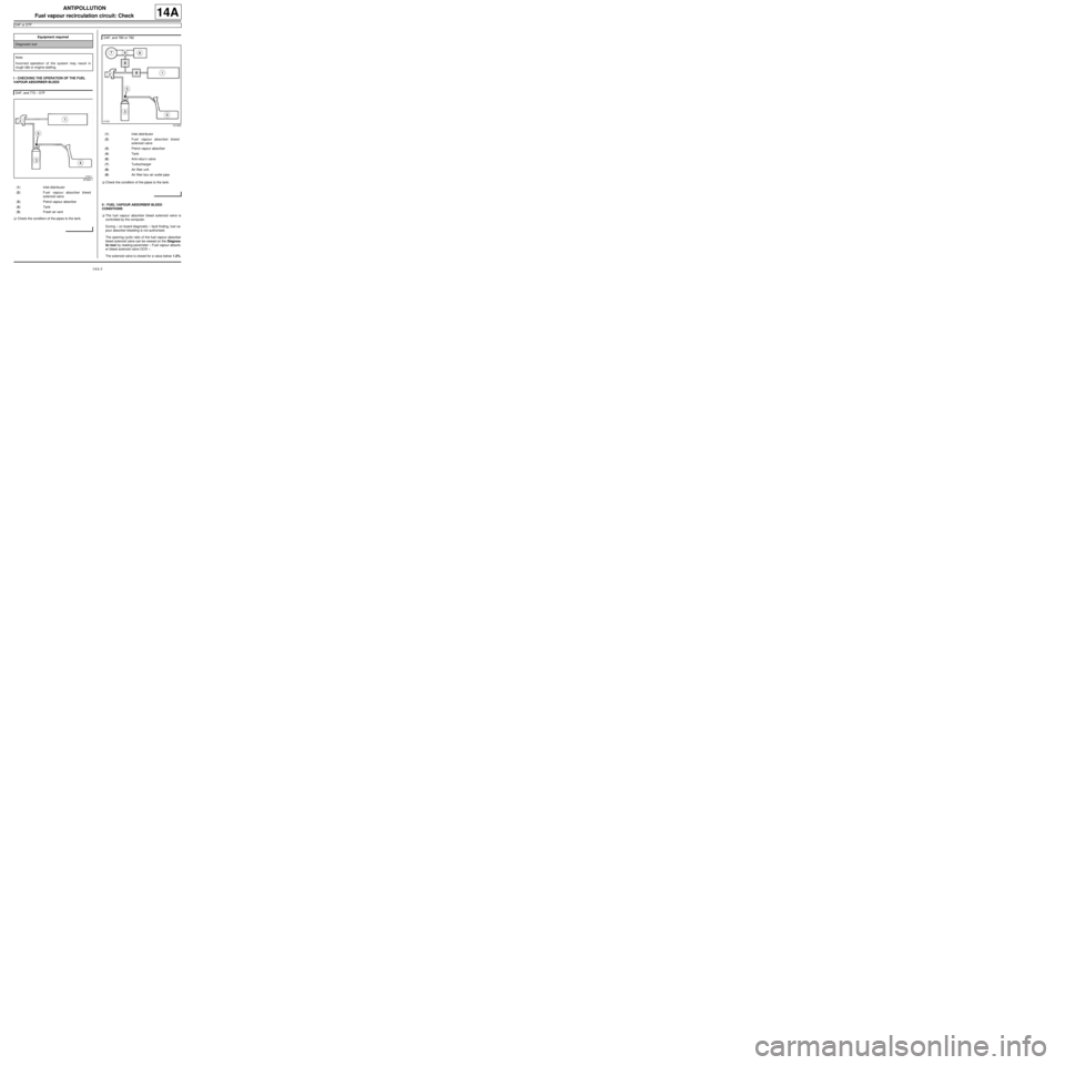
D4F, and 772 – D7F
97393-1
(1) Inlet distributor
(2) Fuel vapour absorber bleed
solenoid valve
(3) Petrol vapour absorber
(4) Tank
(5) Fresh air vent
D4F, and 780 or 782
121923
(1) Inlet distributor
(2) Fuel vapour absorber bleed
solenoid valve
(3) Petrol vapour absorber
(4) Tank
(6) Anti-retur n valve
(7) Turbocharger
(8) Air filter unit
(9) Air filter box air outlet pipe
Page 425 of 652
14A-7
ANTIPOLLUTION
Fuel vapour absorber: Check
D4F or D7F
14A
I - CHECKING THE FUEL VAPOUR ABSORBER
aOn the fuel vapour absorber, plug the circuit coming
from the fuel tank.
aConnect the pressure gauge of the (Mot. 1311-01)
to the fuel vapour absorber breather outlet.
aWith the engine at idle speed, check that no vacuum
is present at the fuel vapour absorber breather out-
let. In the same way, the control value read by the
Diagnostic tool in parameter « fuel vapour absorb-
er bleed solenoid valve OCR » remains minimal X
less than or equal to 1.5%.
Is there a vacuum?
-Yes: With the ignition off, use a manual vacuum
and pressure pump to apply a vacuum of 500
mbar to the solenoid valve outlet. The vacuum
pressure should not vary by more than 10 mbar
over 30 seconds.
•Does the pressure vary?
-Yes: the solenoid valve is faulty, replace it (see
17B, Petrol injection, Petrol injection: List
and location of components, page 17B-1) .
-No: if it is an electrical problem, check the circuit
(see MR 413 Fault finding, 17B, Petrol injec-
tion, Fault finding - Interpretation of faults,
Canister bleed solenoid valve circuit).
-No: In bleeding condition (see « bleeding
condition » ), the vacuum should increase. In the
same time, the value of the parameter on the Diag-
nostic tool increases.
II - CHECKING THE FUEL VAPOUR ABSORBER-
TANK CONNECTION
aCheck this connection by connecting a manual vac-
uum and pressure pump to the pipe leading to the
fuel vapour absorber.Special tooling required
Mot. 1311-01Pressure gauges and petrol
pressure measur ing unions.
Equipment required
Diagnostic tool
man ual vacuum and pressure pump
Page 426 of 652
14A-8
ANTIPOLLUTION
Fuel vapour absorber bleed solenoid valve: Removal - Refitting
K4M
14A
REMOVAL
I - REMOVAL PREPARATION OPERATION
aDisconnect the battery (see Battery: Removal - Re-
fitting) (80A, Battery).
aRemove:
-the windscreen wiper arms (see Windscreen wip-
er arm: Removal - Refitting) (85A, Wiping -
Washing),
-the scuttle panel grille (see Scuttle panel grille:
Removal - Refitting) (56A, Exterior equipment),
-the scoop under the scuttle panel grille (see Scoop
under the scuttle panel grille: Removal - Refit-
ting) (56A, Exterior equipment).II - REMOVAL OPERATION
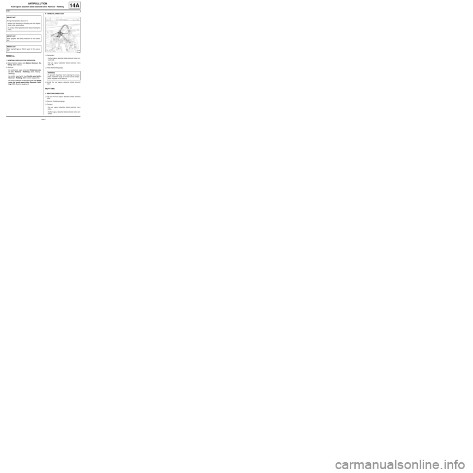
aDisconnect:
-the fuel vapour absorber bleed solenoid valve con-
nector (3) ,
-the fuel vapour absorber bleed solenoid valve
pipes (4) .
aInsert the blanking plugs.
aUnclip the fuel vapour absorber bleed solenoid
valve.
REFITTING
I - REFITTING OPERATION
aClip on the fuel vapour absorber bleed solenoid
valve.
aRemove the blanking plugs.
aConnect:
-the fuel vapour absorber bleed solenoid valve
pipes,
-the fuel vapour absorber bleed solenoid valve con-
nector. IMPORTANT
During this oper ation, be sure to:
-refrain from smoking or bringing red hot objects
close to the working area,
-be careful of fuel splashes when disconnecting the
union.
IMPORTANT
Wear goggles with side protectors for this opera-
tion.
IMPORTANT
Wear leaktight gloves (Nitrile type) for this opera-
tion.
131766
WARNING
To prevent impur ities from entering the circuit,
place protective plugs on all fuel circuit compo-
nents exposed to the open air.
Page 427 of 652
14A-9
ANTIPOLLUTION
Fuel vapour absorber bleed solenoid valve: Removal - Refitting
K4M
14A
II - FINAL OPERATION
aRefit:
-the scoop under the scuttle panel grille (see Scoop
under the scuttle panel grille: Removal - Refit-
ting) (56A, Exterior equipment),
-the scuttle panel grille (see Scuttle panel grille:
Removal - Refitting) (56A, Exterior equipment),
-the windscreen wiper arms (see Windscreen wip-
er arm: Removal - Refitting) (85A, Wiping -
Washing).
aConnect the battery (see Battery: Removal - Refit-
ting) (80A, Battery).