Valve RENAULT TWINGO 2009 2.G Engine And Peripherals Workshop Manual
[x] Cancel search | Manufacturer: RENAULT, Model Year: 2009, Model line: TWINGO, Model: RENAULT TWINGO 2009 2.GPages: 652
Page 540 of 652
19A-30
COOLING
Coolant pump: Removal - Refitting
K4M
19A
REMOVAL
I - REMOVAL PREPARATION OPERATION
aPosition the vehicle on a two-post lift (see Vehicle:
Towing and lifting) (02A, Lifting equipment).
aDrain the cooling system (see 19A, Cooling, Cool-
ing system: Draining - Refilling, page 19A-9) .
aDisconnect the battery (see Battery: Removal - Re-
fitting) (80A, Battery).aRemove:
-the engine undertray,
-the front right-hand wheel (see Wheel: Removal -
Refitting) (35A, Wheels and tyres),
-the front right-hand wheel arch liner (see Front
wheel arch liner: Removal - Refitting) (55A, Ex-
terior protection),
-the front bumper (see Front bumper: Removal -
Refitting) (55A, Exterior protection),
-the headlights (see Halogen headlight: Removal
- Refitting) (80B, Headlights),
-the bonnet catch (see Bonnet lock: Removal -
Refitting) (52A, Non-side opening element mecha-
nisms),
-the front upper cross member (see Front upper
cross member: Removal - Refitting) (42A, Upper
front structure),
-the accessories belt (see 11A, Top and front of
engine, Accessories belt: Removal - Refitting,
page 11A-3) ,
-the air filter unit (see 12A, Fuel mixture, Air filter
unit: Removal - Refitting, page 12A-13) ,
-the throttle valve (see 12A, Fuel mixture, Throttle
valve: Removal - Refitting, page 12A-20) ,
-the windscreen wiper arms (see Windscreen wip-
er arm: Removal - Refitting) (85A, Wiping -
Washing),
-the scuttle panel grille (see Scuttle panel grille:
Removal - Refitting) (56A, Exterior equipment),
-the scoop under the scuttle panel grille (see Scoop
under the scuttle panel grille: Removal - Refit-
ting) (56A, Exterior equipment),
-the right-hand suspended engine mounting (see
19D, Engine mounting, Right-hand suspended
engine mounting: Removal - Refitting, page
19D-13) ,
-the crankshaft accessories pulley (see 11A, Top
and front of engine, Crankshaft accessories
pulley: Removal - Refitting, page 11A-20) ,
-the timing belt (see 11A, Top and front of engine,
Timing belt: Removal - Refitting, page 11A-27) ,
-the camshaft dephaser (see 11A, Top and front of
engine, Camshaft dephaser: Removal - Refit-
ting, page 11A-135) . Tightening torquesm
bolt 1 of the coolant
pump27 N.m
bolts 2 to 8 of the water
pump10 N.m
IMPORTANT
When working in the engine compartment, take
care as the radiator fan(s) may start up unexpect-
edly (risk of being cut).
To avoid any risk of serious burns when the engine
is hot:
-do not open the expansion bottle cap,
-do not drain the cooling system,
-do not open the bleed screw(s).
WARNING
Prepare for the flow of fluid, and protect the sur-
rounding components.
WARNING
When carr ying out a repair that requires a complete
change, it is essential to flush the circuit with clean
water, blast compressed air through the circuit to
drive out the water, fill and bleed the circuit and
then measure the effective protection.
The cr iteria to be met are:
-protection down to -25˚C ±± ± ±
2 for cold and temper-
ate countries,
-protection down to -40˚C ±± ± ±
2 for "extreme cold"
countries.
Page 543 of 652
19A-33
COOLING
Coolant pump: Removal - Refitting
K4M
19A
-the scoop under the scuttle panel grille (see Scoop
under the scuttle panel grille: Removal - Refit-
ting) (56A, Exterior equipment),
-the scuttle panel grille (see Scuttle panel grille:
Removal - Refitting) (56A, Exterior equipment),
-the windscreen wiper arms (see Windscreen wip-
er arm: Removal - Refitting) (85A, Wiping -
Washing),
-the throttle valve (see 12A, Fuel mixture, Throttle
valve: Removal - Refitting, page 12A-20) ,
-the air filter unit (see 12A, Fuel mixture, Air filter
unit: Removal - Refitting, page 12A-13) ,
-the accessories belt (see 11A, Top and front of
engine, Accessories belt: Removal - Refitting,
page 11A-3) ,
-the front upper cross member (see Front upper
cross member: Removal - Refitting) (42A, Upper
front structure),
-the bonnet catch (see Bonnet lock: Removal -
Refitting) (52A, Non-side opening element mecha-
nisms),
-the headlights (see Halogen headlight: Removal
- Refitting) (80B, Headlights),
-the front bumper (see Front bumper: Removal -
Refitting) (55A, Exterior protection),
-the front right-hand wheel arch liner (see Front
wheel arch liner: Removal - Refitting) (55A, Ex-
terior protection),
-the front right-hand wheel (see Wheel: Removal -
Refitting) (35A, Wheels and tyres).
aConnect the battery (see Battery: Removal - Refit-
ting) (80A, Battery).
aFill and bleed the cooling system (see 19A, Cool-
ing, Cooling system: Draining - Refilling, page
19A-9) .
aRefit the engine undertray.
Page 552 of 652
19A-42
COOLING
Water chamber: Removal - Refitting
K9K
19A
REMOVAL
I - REMOVAL PREPARATION OPERATION
aPosition the vehicle on a two-post lift (see Vehicle:
Towing and lifting) (02A, Lifting equipment).
aRemove the front engine cover. Special tooling required
Mot. 1448Remote operation pliers for
hose clips .
Tightening torquesm
water chamber bolts10 N.m
intercooler air outlet
pipe clip at the damper
valve end5.5 N.m
IMPORTANT
When working in the engine compartment, take
care as the radiator fan(s) may start up unexpect-
edly (risk of being cut).
To avoid any risk of serious burns when the engine
is hot:
-do not open the expansion bottle cap,
-do not drain the cooling system,
-do not open the bleed screw(s).
WARNING
Before the operation, protect the electrical accesso-
ries to prevent any risk of shor t circuiting and pro-
tect the belts to avoid damaging them.
WARNING
When carr ying out a repair that requires a complete
change, it is essential to flush the circuit with clean
water, blast compressed air through the circuit to
drive out the water, fill and bleed the circuit and
then measure the effective protection.
The cr iteria to be met are:
-protection down to -25˚C ±± ± ±
2 for cold and temper-
ate countries,
-protection down to -40˚C ±± ± ±
2 for "extreme cold"
countries.
WARNING
The coolant helps to keep the engine running prop-
erly (heat exchange).
The system does not operate using pure water.
WARNING
Take care not to damage the bearing faces to pre-
vent any risk of coolant leaks.
Page 553 of 652
19A-43
COOLING
Water chamber: Removal - Refitting
K9K
19A
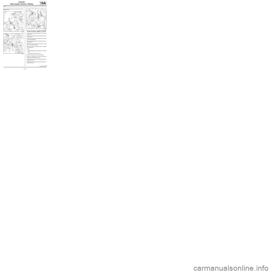
aRemove the air filter unit (see 12A, Fuel mixture,
Air filter unit: Removal - Refitting, page 12A-13) .
aPull the intercooler air inlet pipe clip (1) at the turbo-
charger end.
aDisconnect the intercooler air inlet pipe (2) at the tur-
bocharger end.
aRemove the nut (3) from the intercooler air inlet pipe
at the turbocharger end.
aMove aside the intercooler air inlet pipe (2) at the tur-
bocharger end.
aRemove the nut (4) from the intercooler air outlet
pipe at the damper valve end.
aDisconnect the turbocharging pressure regulator
vacuum pipe (5) .
aUnclip:
-the turbocharging pressure regulator vacuum pipe
at (6) ,
-the brake servo vacuum pipe at (7) .
aDisconnect the brake servo vacuum pipe (8) .
aLoosen the clamp (9) for the air-air intercooler air
outlet pipe at the damper valve end.
aDisconnect the intercooler air outlet pipe (10) at the
damper valve end.
aMove aside the intercooler air outlet pipe (10) at the
damper valve end. K9K, and 718
141222
141213
141217
Page 555 of 652
19A-45
COOLING
Water chamber: Removal - Refitting
K9K
19A
II - REFITTING OPERATION FOR PART
CONCERNED
aRefit the thermostat to the water chamber.
aRefit:
-a new water chamber seal,
-the water chamber.
aTorque tighten the water chamber bolts (10 N.m).
III - FINAL OPERATION
aConnect the cooling hoses on the water chamber.
aPosition the cooling hose clips on the water chamber
using the tool (Mot. 1448).
aClip on the cooling hose of the coolant-oil heat ex-
changer.
aConnect the intercooler air outlet pipe on the side of
the damper valve.
aTorque tighten the intercooler air outlet pipe clip
at the damper valve end (5.5 N.m).
aConnect the brake servo vacuum pipe.
aClip:
-the turbocharging pressure regulator vacuum pipe,
-the vacuum pipe from the brake servo.
aConnect the turbocharging pressure regulator vacu-
um pipe.
aRefit the nuts of the air hoses on the lifting eye.
aConnect the intercooler air inlet pipe at the turbo-
charger end.
aClip on the intercooler air inlet pipe clip at the turbo-
charger end.
aFill the cooling system (see 19A, Cooling, Cooling
system: Draining - Refilling, page 19A-9) .
aRefit the engine cover. K9K, and 718
Page 579 of 652
19A-69
COOLING
Coolant temperature sensor: Removal - Refitting
D4F, and 780
19A
a
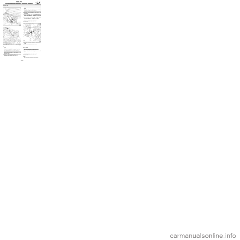
Remove the turbocharger air outlet pipe bolt (3) from
the throttle valve.
aDetach the turbocharger air outlet pipe from the tur-
bocharger in the direction of the arrow (4) .aDisconnect the turbocharger air outlet pipe from the
turbocharger.
aRemove the throttle valve (see 12A, Fuel mixture,
Throttle valve: Removal - Refitting, page 12A-20)
.
aDrain the cooling system (see 19A, Cooling, Cool-
ing system: Draining - Refilling, page 19A-9) .
II - REMOVAL OPERATION FOR PART
CONCERNED
aDisconnect the coolant temperature sensor connec-
tor (6) .
aRemove the coolant temperature sensor.
REFITTING
I - REFITTING PREPARATIONS OPERATION
aAlways replace the coolant temperature sensor O-
ring.
II - REFITTING OPERATION FOR PART
CONCERNED
aRefit:
-the new coolant temperature sensor O-ring,
122833
122673
Note:
If the tightening clip (1) is removed from the tur-
bocharger air outlet pipe, the flexible rubber pipe
(2) and tightening clip (1) must be replaced.
Note:
If the clip (5) is removed from the heat resistant
protector, the latter must be replaced.
114326
Page 580 of 652
19A-70
COOLING
Coolant temperature sensor: Removal - Refitting
D4F, and 780
19A
-the coolant temperature sensor.
aTorque tighten the coolant temperature sensor
(23 Nm).
aConnect the coolant temperature sensor connector.
III - FINAL OPERATION
aRefit the throttle valve (see 12A, Fuel mixture,
Throttle valve: Removal - Refitting, page 12A-20)
.
aPush the turbocharger air outlet pipe clip in the di-
rection of the arrow (7) .
aConnect the turbocharger air outlet pipe onto the tur-
bocharger.
aRefit the turbocharger air outlet pipe bolt on the
throttle valve.
aFill and bleed the cooling system (see 19A, Cool-
ing, Cooling system: Draining - Refilling, page
19A-9) .
122666
Page 599 of 652
19B-17
EXHAUST
Catalytic converter: Removal - Refitting
D4F, and 780 or 782
19B
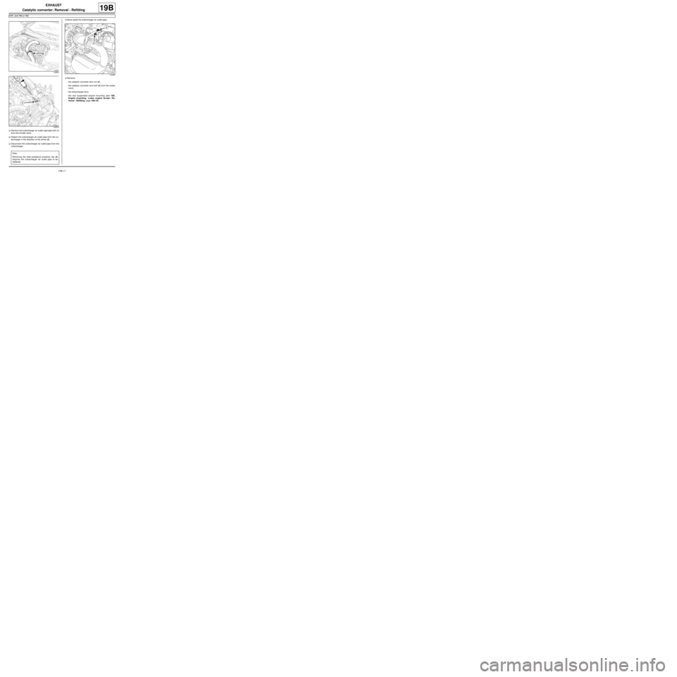
aRemove the turbocharger air outlet rigid pipe bolt (1)
from the throttle valve.
aDetach the turbocharger air outlet pipe from the tur-
bocharger in the direction of the arrow (2) .
aDisconnect the turbocharger air outlet pipe from the
turbocharger.aMove aside the turbocharger air outlet pipe.
aRemove:
-the catalytic converter strut nut (4) ,
-the catalytic converter strut bolt (5) from the rocker
cover,
-the turbocharger strut.
-the rear suspended engine mounting (see 19D,
Engine mounting, Lower engine tie-bar: Re-
moval - Refitting, page 19D-18) .
122834
122673
Note:
Removing the heat-resistance protector clip (3)
requires the turbocharger air outlet pipe to be
replaced.
120959
Page 602 of 652
19B-20
EXHAUST
Catalytic converter: Removal - Refitting
D4F, and 780 or 782
19B
-the new nuts with the catalytic converter spacers
on the turbocharger.
aAttach the downstream oxygen sensor wiring har-
ness to the catalytic converter.
aClip on the catalytic converter downstream oxygen
sensor connector.
aConnect the catalytic converter downstream oxygen
sensor connector.
III - FINAL OPERATION
aRefit:
-the catalytic converter lower exhaust bracket,
-the bracket bolt on the gearbox,
-the bracket bolts on the engine,
-the catalytic converter side exhaust bracket,
-the catalytic converter side bracket bolts,
-the engine side bracket bolts.
aTorque tighten:
-the catalytic converter lower bracket bolt on the
gearbox (44 N.m),
-the bolts of the catalytic converter lower brack-
et on the engine (25 N.m),
-the side bracket bolts on the catalytic converter
(21 N.m),
-the side bracket bolts on the engine (21 N.m),
-the catalytic converter nuts on the turbocharger
(initial torque) (20 N.m),
-the catalytic converter nuts on the turbocharger
(30 N.m),
-the bolts of the catalytic converter lower brack-
et on the catalytic converter (initial torque) (20
N.m),
-the bolts of the catalytic converter lower brack-
et on the catalytic converter (30 N.m).
aRefit:
-the exhaust downpipe,
-the intermediate pipe clip.
aTighten the intermediate pipe clip.
aRefit the exhaust downpipe bolts on the catalytic
converter.
aTorque tighten the exhaust downpipe bolts (21
N.m).aRefit:
-the rear suspended engine mounting (see 19D,
Engine mounting, Lower engine tie-bar: Re-
moval - Refitting, page 19D-18) ,
-the turbocharger strut.
-the catalytic converter strut bolt on the rocker cov-
er,
-the catalytic converter strut nut.
aTorque tighten:
-the catalytic converter strut nut (21 N.m),
-the catalytic converter strut bolt on the rocker
cover (21 N.m).
aPosition the turbocharger air outlet pipe.
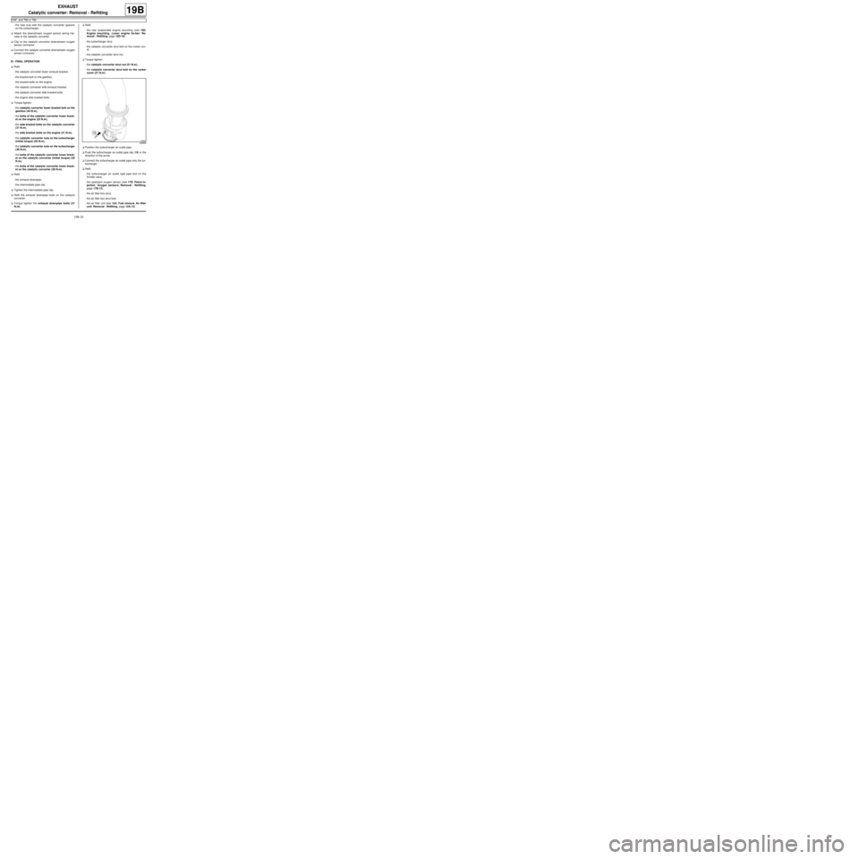
aPush the turbocharger air outlet pipe clip (15) in the
direction of the arrow.
aConnect the turbocharger air outlet pipe onto the tur-
bocharger.
aRefit:
-the turbocharger air outlet rigid pipe bolt on the
throttle valve,
-the upstream oxygen sensor (see 17B, Petrol in-
jection, Oxygen sensors: Removal - Refitting,
page 17B-13) ,
-the air filter box strut,
-the air filter box strut bolt,
-the air filter unit (see 12A, Fuel mixture, Air filter
unit: Removal - Refitting, page 12A-13) .
122666