Valve RENAULT TWINGO 2009 2.G Engine And Peripherals Workshop Manual
[x] Cancel search | Manufacturer: RENAULT, Model Year: 2009, Model line: TWINGO, Model: RENAULT TWINGO 2009 2.GPages: 652
Page 3 of 652
TWINGO - Chapitre 1
Contents
Pages
TWINGO - Chapitre 1ContentsPages
10AENGINE AND CYLINDER BLOCK
ASSEMBLY
Crankshaft seal on timing
end: Removal - Refitting 10A-1
Crankshaft seal, gearbox
end: Removal - Refitting 10A-3
Lower cover: Removal -
Refitting 10A-6
Engine oil: Draining -
Refilling 10A-22
Oil filter: Removal - Refitting 10A-29
Oil-coolant heat exchanger:
Removal - Refitting 10A-33
Conrod bearing shell:
Removal - Refitting 10A-37
Oil pressure sensor:
Removal - Refitting 10A-45
Oil pump: Removal -
Refitting 10A-50
Oil pressure: Check 10A-59
Multifunction suppor t:
Removal - Refitting 10A-63
Engine - gearbox assembly:
Removal - Refitting 10A-74
Valves: Adjustment 10A-105
Flywheel: Removal - Refitting 10A-10711A TOP AND FRONT OF ENGINE
Pressure at end of
compression: Check 11A-1
Accessories belt: Removal -
Refitting 11A-3
Crankshaft accessories
pulley: Removal - Refitting 11A-20
Timing belt: Removal -
Refitting 11A-27
Rocker cover: Removal -
Refitting 11A-66
Camshaft: Removal -
Refitting 11A-82
Cylinder head: Removal -
Refitting 11A-114
Camshaft dephaser :
Removal - Refitting 11A-135
Camshaft seal, timing end:
Removal - Refitting 11A-138
Oil decanter: Removal -
Refitting 11A-147
12A FUEL MIXTURE
Air inlet: Description 12A-1
Air filter: Removal - Refitting 12A-6
Air filter unit: Removal -
Refitting 12A-13
Page 4 of 652
Contents
Air resonator : Removal -
Refitting 12A-19
Throttle valve: Removal -
Refitting 12A-20
Throttle valve: Cleaning 12A-26
Air flowmeter: Removal -
Refitting 12A-28
Inlet distributor: Removal -
Refitting 12A-29
Injector holder shim:
Removal - Refitting 12A-45
Exhaust manifold: Removal -
Refitting 12A-48
12B TURBOCHARGING
Turbocharging: Precautions
for the repair 12B-1
Turbocharger: Removal -
Refitting 12B-4
Turbocharger oil pipe:
Removal - Refitting 12B-12
Intercooler : Removal -
Refitting 12B-18
13A FUEL SUPPLY
Diesel supply circuit:
Operating diagram 13A-1
Manual pr iming pump:
Removal - Refitting 13A-2
Fuel filter : Removal -
Refitting 13A-4
Electric diesel fuel heater:
Removal - Refitting 13A-7
Fuel circuit: Operating
diagram 13A-8 12A FUEL MIXTUREFuel pressure: Check 13A-9
Fuel flow: Check 13A-14
13B DIESEL INJECTION
Diesel injection: Precautions
for the repair 13B-1
Diesel injection: List and
location of components 13B-8
Diesel injection computer:
Removal - Refitting 13B-13
Camshaft position sensor:
Removal - Refitting 13B-14
Crankshaft position sensor:
Removal - Refitting 13B-15
High pressure pump:
Removal - Refitting 13B-16
Flow actuator: Removal -
Refitting 13B-26
Venturi: Removal - Refitting 13B-31
High pressure pipe: Check 13B-34
High pressure pipe between
pump and rail: Removal -
Refitting 13B-35
High pressure pipe between
rail and injector: Removal -
Refitting 13B-39
Injector rail: Removal -
Refitting 13B-43
Rail pressure sensor:
Removal - Refitting 13B-48
Fuel temperature sensor:
Removal - Refitting 13B-49
Injector leak flow: Check 13B-51
Accelerometer : Removal -
Refitting 13B-53 13A FUEL SUPPLY
Page 5 of 652
Contents
13C PREHEATING
Pre-postheating unit:
Removal - Refitting 13C-1
Heater plugs: Removal -
Refitting 13C-2
14A ANTIPOLLUTION
Oil vapour rebreathing
circuit: Descriptions 14A-1
Fuel vapour recirculation
circuit: Operating diagram 14A-2
Fuel vapour recirculation
circuit: Check 14A-3
Fuel vapour absorber:
Removal - Refitting 14A-4
Fuel vapour absorber: Check 14A-7
Fuel vapour absorber bleed
solenoid valve: Removal -
Refitting 14A-8
Exhaust gas recirculation
solenoid valve: Removal -
Refitting 14A-10
Exhaust gas cooler: Removal
- Refitting 14A-11
Exhaust gas recirculation
assembly: Removal -
Refitting 14A-15
Exhaust gas recirculation
rigid pipe: Removal -
Refitting 14A-19
16A STARTING - CHARGING
Alternator: Removal -
Refitting 16A-1
Star ter: Removal - Refitting 16A-10
Alternator pulley: Removal -
Refitting 16A-1717A IGNITION
Coils: Removal - Refitting 17A-1
Plugs: Removal - Refitting 17A-12
17B PETROL INJECTION
Petrol injection: List and
location of components 17B-1
Oxygen sensors: Removal -
Refitting 17B-13
Petrol injection computer:
Removal - Refitting 17B-20
Pinking sensor: Removal -
Refitting 17B-23
Crankshaft position sensor:
Removal - Refitting 17B-25
Injector rail - Injectors:
Removal - Refitting 17B-27
19A COOLING
Engine cooling system:
Specifications 19A-1
Engine cooling system:
Check 19A-2
Engine cooling circuit: List
and location of components 19A-4
Engine cooling system:
Operating diagram 19A-5
Cooling system: Draining -
Refilling 19A-9
Cooling radiator: Removal -
Refitting 19A-12
Coolant pump: Removal -
Refitting 19A-24
Thermostat: Removal -
Refitting 19A-34
Water chamber: Removal -
Refitting 19A-40
Page 7 of 652
10A-1
ENGINE AND CYLINDER BLOCK ASSEMBLY
Crankshaft seal on timing end: Removal - Refitting
K4M
10A
REMOVAL
I - REMOVAL PREPARATION OPERATION
aPosition the vehicle on a two-post lift (see Vehicle:
Towing and lifting) (02A, Lifting equipment).
aDisconnect the battery (see Battery: Removal - Re-
fitting) (80A, Battery).
aRemove:
-the engine undertray,
-the front right-hand wheel (see Wheel: Removal -
Refitting) (35A, Wheels and tyres),
-the front right-hand wheel arch liner (see Front
wheel arch liner: Removal - Refitting) (55A, Ex-
terior protection),
-the front bumper (see Front bumper: Removal -
Refitting) (55A, Exterior protection),
-the headlights (see Halogen headlight: Removal
- Refitting) (80B, Headlights),
-the bonnet catch (see Bonnet lock: Removal -
Refitting) (52A, Non-side opening element mecha-
nisms),
-the front upper cross member (see Front upper
cross member: Removal - Refitting) (42A, Upper
front structure),
-the accessories belt (see 11A, Top and front of
engine, Accessories belt: Removal - Refitting,
page 11A-3) ,
-the air filter unit (see 12A, Fuel mixture, Air filter
unit: Removal - Refitting, page 12A-13) ,
-the throttle valve (see 12A, Fuel mixture, Throttle
valve: Removal - Refitting, page 12A-20) ,
-the windscreen wiper arms (see Windscreen wip-
er arm: Removal - Refitting) (85A, Wiping -
Washing),
-the scuttle panel grille (see Scuttle panel grille:
Removal - Refitting) (56A, Exterior equipment),
-the scoop under the scuttle panel grille (see Scoop
under the scuttle panel grille: Removal - Refit-
ting) (56A, Exterior equipment),-the right-hand suspended engine mounting (see
19D, Engine mounting, Right-hand suspended
engine mounting: Removal - Refitting, page
19D-13) ,
-the crankshaft accessories pulley (see 11A, Top
and front of engine, Crankshaft accessories
pulley: Removal - Refitting, page 11A-20) ,
-the timing belt (see 11A, Top and front of engine,
Timing belt: Removal - Refitting, page 11A-27) ,
-the camshaft dephaser (see 11A, Top and front of
engine, Camshaft dephaser: Removal - Refit-
ting, page 11A-135) .
II - REMOVAL OPERATION
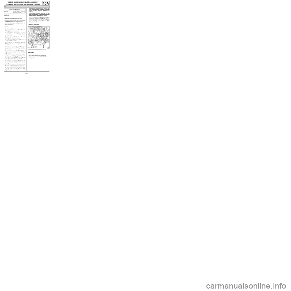
aRemove the crankshaft timing end seal (1) .
REFITTING
I - REFITTING PREPARATION OPERATION
aparts always to be replaced: Crankshaft seal on
timing end. Special tooling required
Mot. 1385Tool for fitting the crankshaft
seal, timing end (35 x 47 x 7).
130542
Page 8 of 652
10A-2
ENGINE AND CYLINDER BLOCK ASSEMBLY
Crankshaft seal on timing end: Removal - Refitting
K4M
10A
aUse SURFACE CLEANER (see Vehicle: Parts
and consumables for the repair) (04B, Consuma-
bles - Products) to clean and degrease:
-the mating face of the crankshaft seal at the timing
end,
-the crankshaft seal housing at the timing end of the
cylinder block.
II - REFITTING OPERATION
aRefit a new crankshaft seal at the timing end, using
the tool (Mot. 1385) (2) .
III - FINAL OPERATION
aRefit:
-the camshaft dephaser (see 11A, Top and front of
engine, Camshaft dephaser: Removal - Refit-
ting, page 11A-135) ,
-the timing belt (see 11A, Top and front of engine,
Timing belt: Removal - Refitting, page 11A-27) ,
-the crankshaft accessories pulley (see 11A, Top
and front of engine, Crankshaft accessories
pulley: Removal - Refitting, page 11A-20) ,
-the right-hand suspended engine mounting (see
19D, Engine mounting, Right-hand suspended
engine mounting: Removal - Refitting, page
19D-13) ,-the scoop under the scuttle panel grille (see Scoop
under the scuttle panel grille: Removal - Refit-
ting) (56A, Exterior equipment),
-the scuttle panel grille (see Scuttle panel grille:
Removal - Refitting) (56A, Exterior equipment),
-the windscreen wiper arms (see Windscreen wip-
er arm: Removal - Refitting) (85A, Wiping -
Washing),
-the throttle valve (see 12A, Fuel mixture, Throttle
valve: Removal - Refitting, page 12A-20) ,
-the air filter unit (see 12A, Fuel mixture, Air filter
unit: Removal - Refitting, page 12A-13) ,
-the accessories belt (see 11A, Top and front of
engine, Accessories belt: Removal - Refitting,
page 11A-3) ,
-the front upper cross member (see Front upper
cross member: Removal - Refitting) (42A, Upper
front structure),
-the bonnet catch (see Bonnet lock: Removal -
Refitting) (52A, Non-side opening element mecha-
nisms),
-the headlights (see Halogen headlight: Removal
- Refitting) (80B, Headlights),
-the front bumper (see Front bumper: Removal -
Refitting) (55A, Exterior protection),
-the front right-hand wheel arch liner (see Front
wheel arch liner: Removal - Refitting) (55A, Ex-
terior protection),
-the front right-hand wheel (see Wheel: Removal -
Refitting) (35A, Wheels and tyres),
-the engine undertray.
aConnect the battery (see Battery: Removal - Refit-
ting) (80A, Battery). WARNING
The joint faces must be clean, dr y and free from
grease (avoid finger marks).
14523
Page 65 of 652
10A-59
ENGINE AND CYLINDER BLOCK ASSEMBLY
Oil pressure: Check
D4F or D7F or K9K
10A
I - RECOMMENDATIONS FOR REPAIR
a
II - PARTS AND CONSUMABLES FOR THE REPAIR
WORK
aParts which must be replaced:
-the sump plug sealing washer (in the event of an oil
change),
-oil filter (if removed).
aConsumable:
-Engine oil (see Engine oil: Specifications) (Tech-
nical Note 6013, 04A, Lubricants).
III - CHECK
aRemove the oil pressure sensor (see 10A, Engine
and cylinder block assembly, Oil pressure sen-
sor: Removal - Refitting, page 10A-45) .aCheck the correct operation of the oil pressure sen-
sor valve using the roll pin punch with a diameter of
2 mm and the multimeter. Special tooling required
Mot. 836-05Oil pressure gauge kit.
Mot. 1495-0122 mm socket for removal -
refitting of oxygen sensors.
Equipment required
roll pin punch
multimeter
1/2" long socket (12.7 mm square dr ive)
WARNING
Always check the oil level using the dipstick.
Do not exceed the maximum level on the dipstick
(could destroy the engine).
Correct the engine oil level if necessary before
delivering the vehicle to the customer.
Note:
When topping up the engine oil, always leave at
least 10 minutes before checking the level with a
dipstick.
It is essential to monitor the engine oil pressure
as the engine oil temperature rises (approxi-
mately 80˚C or the first time the engine cool-
ing fan is activated).
Page 83 of 652
10A-77
ENGINE AND CYLINDER BLOCK ASSEMBLY
Engine - gearbox assembly: Removal - Refitting
D4F or D7F
10A
a
aUndo the clip from the intercooler outlet pipe.
aDisconnect the intercooler outlet air pipe.
aRemove the turbocharger air outlet rigid pipe bolt (9)from the throttle valve.
aDetach the turbocharger air outlet pipe from the tur-
bocharger in the direction of the arrow (10) .
aDisconnect the turbocharger air outlet pipe from the
turbocharger.
aUnclip the intercooler air inlet pipe.
aDisconnect the intercooler air inlet pipe from the in-
tercooler.
aRemove the turbocharger air outlet pipe.
aDisconnect the air filter box air inlet pipe from the air
filter box cover (12) .
aRemove:
-the air filter unit air inlet pipe bolt from the cross
member (13) ,
-the air filter unit air inlet pipe.
aDrain:
-the cooling system (see 19A, Cooling, Cooling
system: Draining - Refilling, page 19A-9) ,
-the gearbox (see Manual gearbox oils: Draining -
Filling) (21A, Manual gearbox),
-the engine if necessary (see 10A, Engine and cyl-
inder block assembly, Engine oil: Draining - Re-
filling, page 10A-22) .
aAttach the cooling unit to the engine.
aDisconnect:
-the heater matrix hoses,
-the brake servo pipe on the brake servo,
-the petrol vapour rebreathing solenoid valve con-
nector,
-the petrol vapour rebreather pipe. D4F, and 780 or 782
122833
122673
Note:
If the turbocharger outlet air pipe tightening clip
(7) is removed, the rubber flexible pipe (8) and
the tightening clip (7) must be replaced.
Note:
If the clip (11) is removed from the heat resistant
protector, the latter must be replaced.
Page 90 of 652
10A-84
ENGINE AND CYLINDER BLOCK ASSEMBLY
Engine - gearbox assembly: Removal - Refitting
D4F or D7F
10A
aRefit:
-the air conditioning pipe bolt on the dehydrator res-
ervoir,
-the air conditioning pipe bolts on the compressor.
aTighten:
-the air conditioning pipe bolts on the dehydrator
reservoir,
-the air conditioning pipe bolts on the compressor.
aFill the refrigerant circuit (see Refrigerant circuit:
Draining - Filling) (62A, Air conditioning).
aConnect:
-the petrol vapour rebreathing solenoid valve con-
nector,
-the brake servo pipe on the brake servo,
-the heater matrix hoses.
aFit the cooling unit.
aRefill:
-the engine oil, if necessary (see 10A, Engine and
cylinder block assembly, Engine oil: Draining -
Refilling, page 10A-22) ,
-the gearbox oil (see Manual gearbox oils: Drain-
ing - Filling) ,
-and bleed the cooling system (see 19A, Cooling,
Cooling system: Draining - Refilling, page 19A-
9) .
aRefit:
-the air filter unit air inlet pipe,
-the air filter unit air inlet pipe bolt on the cross
member.
aConnect the air filter box air inlet pipe on the air filter
box cover.
aRefit the turbocharger outlet air pipe.
aPush the intercooler air inlet pipe clip.
aConnect the intercooler air inlet pipe on the inter-
cooler.aPush the turbocharger outlet air pipe clip, following
the direction shown by the arrow (23) .
aConnect the turbocharger air outlet pipe onto the tur-
bocharger.
aRefit the turbocharger outlet rigid air pipe bolt on the
throttle valve.
aConnect the intercooler air outlet pipe to the inter-
cooler.
aTighten the intercooler air outlet pipe clip.
aRefit:
-the cooling radiator upper bolts.
-the air filter unit air inlet pipe,
-the air filter box air inlet pipe on the cross member,
aPosition the expansion bottle.
aRefit the expansion bottle bolt.
aClip the bonnet opening release cable on to the cool-
ing fan assembly.
aPosition the earth straps.
aRefit the earth strap nuts on the front right-hand side
member. D4F, and 780 or 782
122666
D4F or D7F, and 772
Page 92 of 652
10A-86
ENGINE AND CYLINDER BLOCK ASSEMBLY
Engine - gearbox assembly: Removal - Refitting
K9K
10A
REMOVAL
I - REMOVAL PREPARATION OPERATION
aPosition the vehicle on a two-post lift (see Vehicle:
Towing and lifting) (02A, Lifting equipment).
aRemove the battery (see ) (80A, Battery).
aRemove the air inlet pipe (1) from the air filter unit.aRemove the air filter unit (see 12A, Fuel mixture,
Air filter unit: Removal - Refitting, page 12A-13)
aDisconnect:
-the turbocharger regulation solenoid valve pipes
(2) and (3) ,
-the turbocharger regulation solenoid valve connec-
tor (4) .
aUnclip:
-the turbocharger regulation solenoid valve pipes,
-the turbocharger regulation solenoid valve wiring.
aDisconnect the brake servo non-return valve pipe
from the vacuum pump.
aRemove:
-the battery tray (see Battery tray: Removal - Re-
fitting) (80A, Battery),
-the diesel injection computer (see 13B, Diesel in-
jection, Diesel injection computer: Removal -
Refitting, page 13B-13) ,
-the front wheels (see Wheel: Removal - Refitting)
(35A, Wheels and tyres),
-the front wheel arch liners (see Front wheel arch
liner: Removal - Refitting) (55A, Exterior protec-
tion), Special tooling required
Mot. 1448Remote operation pliers for
hose clips .
Equipment required
refrigerant charging station
safety strap(s)
IMPORTANT
Consult the safety and cleanliness advice and oper-
ation recommendations before carrying out any
repair (see 13B, Diesel injection, Diesel injec-
tion: Precautions for the repair, page 13B-1) .
IMPORTANT
Wear protective gloves during the operation.
120038
K9K, and 718
141212
Page 100 of 652
10A-94
ENGINE AND CYLINDER BLOCK ASSEMBLY
Engine - gearbox assembly: Removal - Refitting
K9K
10A
aDetach the « engine cooling radiator - air condition-
ing condenser - intercooler » assembly from the
front upper cross member.
aClip on the clip of the intercooler air inlet pipe.
aConnect:
-the intercooler air outlet pipe,
-the intercooler air inlet pipe.
aTighten the clip on the intercooler outlet pipe.
aDetach the « engine cooling radiator - condenser »
assembly from the front upper cross member.
aRefit:
-the front bumper (see Front bumper: Removal -
Refitting) (55A, Exterior protection),
-the front wheel arch liners (see Front wheel arch
liner: Removal - Refitting) (55A, Exterior protec-
tion),
-the front wheels (see Wheel: Removal - Refitting)
(35A, Wheels and tyres),
-the diesel injection computer (see 13B, Diesel in-
jection, Diesel injection computer: Removal -
Refitting, page 13B-13) ,
-the battery tray (see Battery tray: Removal - Re-
fitting) (80A, Battery),
-the non-return valve pipe on the vacuum pump.aClip:
-the turbocharger regulation solenoid valve wiring,
-the turbocharger regulation solenoid valve pipes.
aConnect:
-the turbocharger regulation solenoid valve connec-
tor,
-the turbocharger regulation solenoid valve pipes.
aRefit the air filter unit (see 12A, Fuel mixture, Air fil-
ter unit: Removal - Refitting, page 12A-13) .
aRefit:
-the air pipe at the air filter unit inlet,
-the battery (see ) (80A, Battery).
aRefill:
-the gearbox (see Sequential gearbox oil: Drain-
ing - Filling) (21A, Manual gearbox),
-the engine cooling system (see 19A, Cooling,
Cooling system: Draining - Refilling, page 19A-
9) ,
-the engine if necessary (see 10A, Engine and cyl-
inder block assembly, Engine oil: Draining - Re-
filling, page 10A-22) ,
-the refrigerant circuit using a refrigerant charging
station (see Refrigerant circuit: Draining - Fill-
ing) (62A, Air conditioning) (if fitted),
-the brake fluid reservoir.
aBleed the clutch circuit (see Clutch circuit: Bleed)
(37A, Mechanical component controls). K9K, and 718
K9K, and 740
K9K, and 718