RENAULT TWINGO 2009 2.G Engine And Peripherals Workshop Manual
TWINGO 2009 2.G
RENAULT
RENAULT
https://www.carmanualsonline.info/img/7/1710/w960_1710-0.png
RENAULT TWINGO 2009 2.G Engine And Peripherals Workshop Manual
Trending: radiator, check oil, recommended oil, ABS, headlights, dead battery, change wheel
Page 581 of 652
19A-71
COOLING
Coolant temperature sensor: Removal - Refitting
K4M
19A
REMOVAL
I - REMOVAL PREPARATION OPERATION
aRemove the air filter unit (see 12A, Fuel mixture,
Air filter unit: Removal - Refitting, page 12A-13) .II - REMOVAL OPERATION
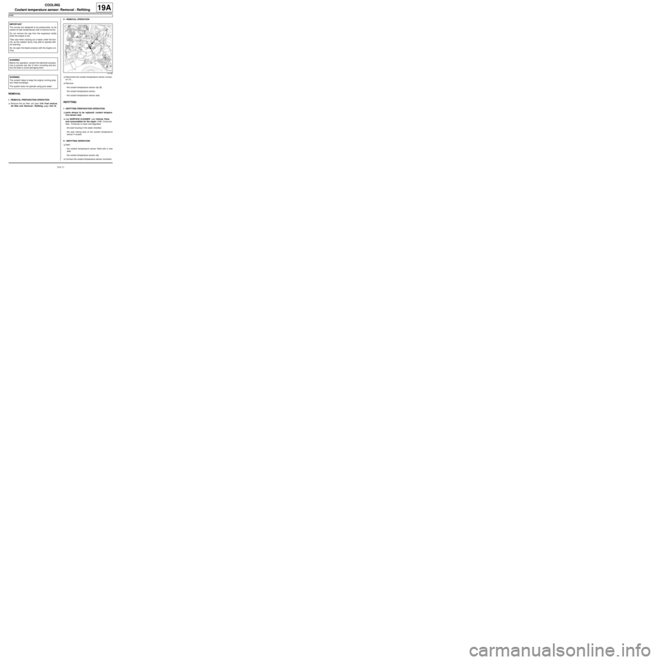
aDisconnect the coolant temperature sensor connec-
tor (1) .
aRemove:
-the coolant temperature sensor clip (2) ,
-the coolant temperature sensor,
-the coolant temperature sensor seal.
REFITTING
I - REFITTING PREPARATION OPERATION
aparts always to be replaced: coolant tempera-
ture sensor seal.
aUse SURFACE CLEANER (see Vehicle: Parts
and consumables for the repair) (04B, Consuma-
bles - Products) to clean and degrease:
-the seal housing in the water chamber,
-the seal mating face of the coolant temperature
sensor if reused.
II - REFITTING OPERATION
aRefit:
-the coolant temperature sensor fitted with a new
seal,
-the coolant temperature sensor clip.
aConnect the coolant temperature sensor connector. IMPORTANT
The circuits are designed to be pressurised, so be
careful at high temperatures (risk of serious burns).
Do not remove the cap from the expansion bottle
while the engine is hot.
Take care when carrying out a repair under the bon-
net, as the radiator fan(s) may start to operate with-
out warning.
Do not open the bleed screw(s) with the engine run-
ning.
WARNING
Before the operation, protect the electrical accesso-
ries to prevent any risk of shor t circuiting and pro-
tect the belts to avoid damaging them.
WARNING
The coolant helps to keep the engine running prop-
erly (heat exchange).
The system does not operate using pure water.
131762
Page 582 of 652
19A-72
COOLING
Coolant temperature sensor: Removal - Refitting
K4M
19A
III - FINAL OPERATION
aRefit the air filter unit (see 12A, Fuel mixture, Air fil-
ter unit: Removal - Refitting, page 12A-13) .
aPerform the following operations:
-top up the coolant level,
-bleed the cooling system (see 19A, Cooling, Cool-
ing system: Draining - Refilling, page 19A-9) .
Page 583 of 652
19B-1
EXHAUST
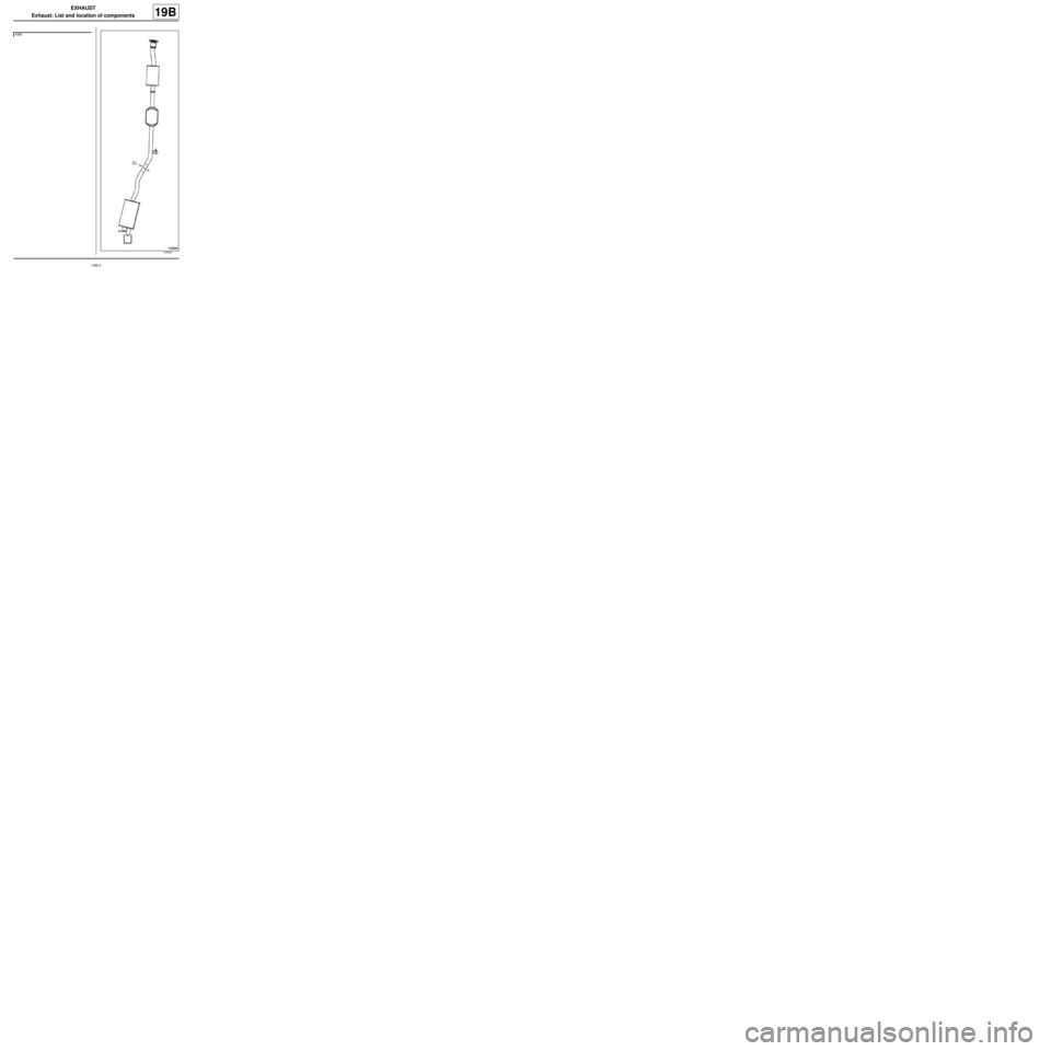
Exhaust: List and location of components
19B
Page 584 of 652
19B-2
EXHAUST
Exhaust: List and location of components
19B
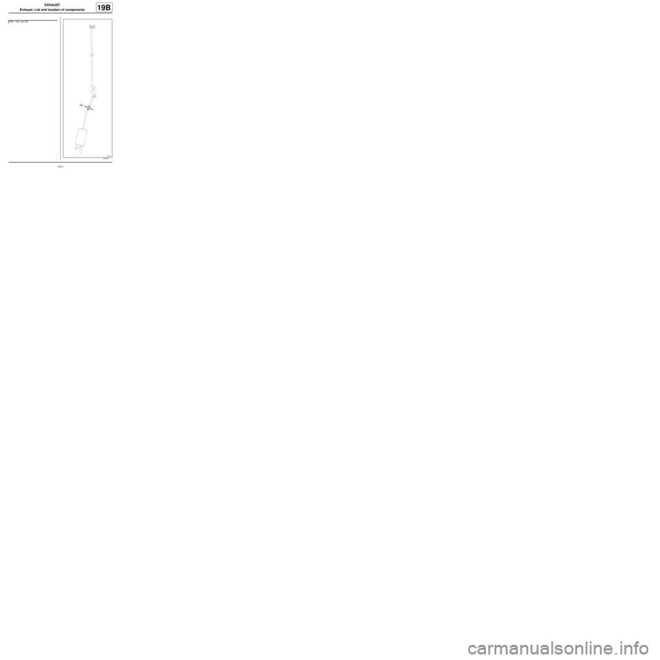
K9K – D4F, and 780
121642
Page 585 of 652
19B-3
EXHAUST
Exhaust: List and location of components
19B
(ZC) : Area to be cut
Page 586 of 652
19B-4
EXHAUST
Exhaust: List and location of components
19B
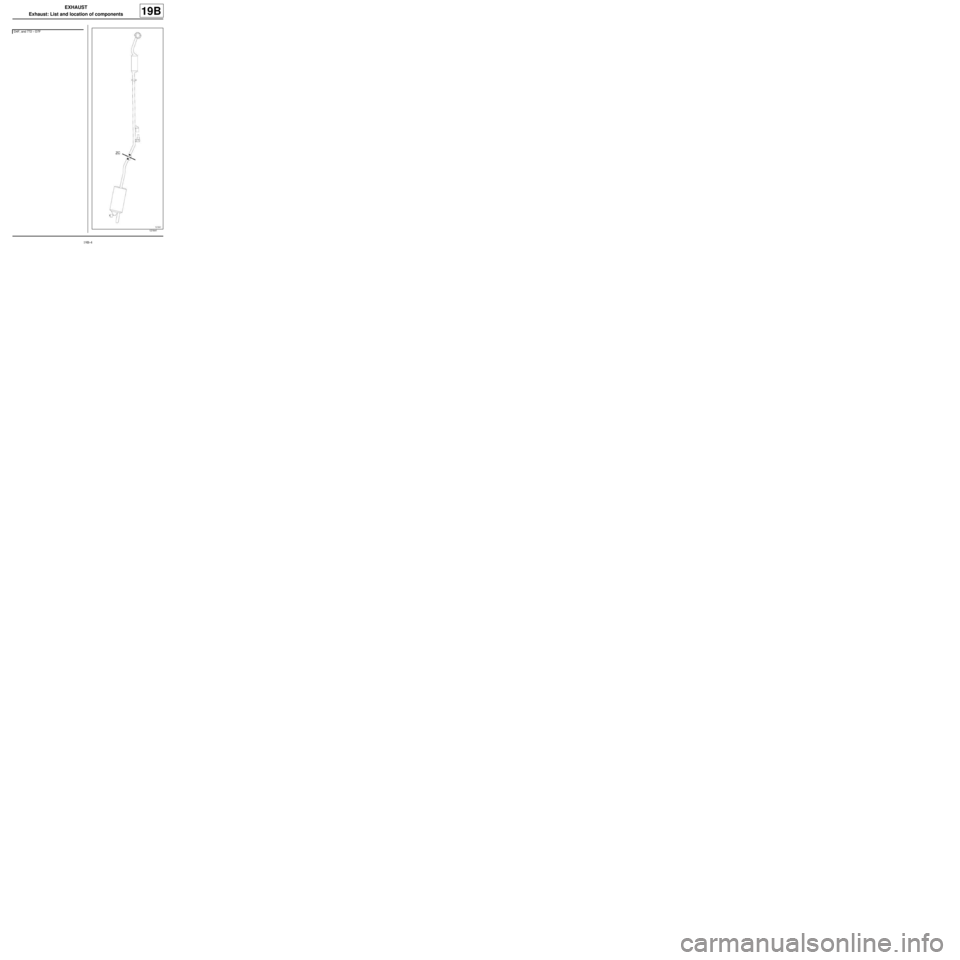
D4F, and 772 – D7F
121641
Page 587 of 652
19B-5
EXHAUST
Exhaust: List and location of components
19B
(ZC) : Area to be cut
Page 588 of 652
19B-6
EXHAUST
Exhaust: List and location of components
19B
K4M
132480
Page 589 of 652
19B-7
EXHAUST
Exhaust: List and location of components
19B
(ZC) : Area to be cut
Page 590 of 652
19B-8
EXHAUST
Exhaust: Precautions for the repair
19B
I - PARTS AND CONSUMABLES FOR THE REPAIR
1 - Parts always to be replaced:
- the exhaust trunking (if fitted)
- the seal or sealing ring on the connection between the
catalytic converter or catalytic pre-converter and the
rest of the exhaust system
- the exhaust clip(s) (if fitted)
2 - Consumables (see part no. in Technical Note
5068, 04B, Consumables - Products):
- exhaust mastic
- surface cleaner
- abrasive pads
II - ADVICE TO OBSERVE
1 - During removal and refitting, the catalytic converter
or catalytic pre-converter must not receive any knocks
or impacts as this could damage it.
2 - The whole exhaust pipe is made of stainless steel.
3 - After working on the bracket between the catalytic
converter or catalytic pre-converter and the rest of the
exhaust system, ensure that the connection is perfectly
sealed.
To do this:
-clean the pressure faces of the connection using the
ABRASIVE PADS,-degrease the pressure faces of the connection using
SURFACE CLEANER and clean cloths,
-always replace the seal or sealing ring on the connec-
tion.
III - SPECIAL NOTES ON THE SINGLE UNIT
EXHAUST PIPE
1 - Cutting the single unit exhaust pipe
The exhaust pipe is a « single unit type » .
To replace different parts of the exhaust system it must
be cut.
To do this be sure to carry out these precautions in the
following order:
-correctly identify the area to be cut, as explained be-
low,
-use the cutting tool correctly (Mot. 1199-01),
-position the exhaust trunking correctly.
2 - Identifying the area of the exhaust system to be
cut
Two marks made on the exhaust system define the
area to be cut (see Exhaust: Parts and consumables
for the repair) (see MR for vehicle concerned, 19B,
Exhaust).
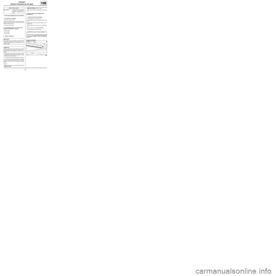
Example of cutting area Special tooling required
Mot. 1199-01Exhaust pipe cutter (diame-
ter 35/50 mm and diameter
50/65mm). Complete kit in a
case.
IMPORTANT
Do not park and run the engine in a place where
combustible substances and materials such as
grass or leaves can come into contact with the hot
exhaust system.
IMPORTANT
Catalytic converters contain ceramic fibres , these
are contained within a closed unit, and cannot dis-
perse. Drilling or cutting catalytic converters is pro-
hibited.
99226
Trending: brake, trunk, timing belt, wipers, power steering, width, air filter

