oil RENAULT TWINGO 2009 2.G Engine And Peripherals Repair Manual
[x] Cancel search | Manufacturer: RENAULT, Model Year: 2009, Model line: TWINGO, Model: RENAULT TWINGO 2009 2.GPages: 652
Page 65 of 652
10A-59
ENGINE AND CYLINDER BLOCK ASSEMBLY
Oil pressure: Check
D4F or D7F or K9K
10A
I - RECOMMENDATIONS FOR REPAIR
a
II - PARTS AND CONSUMABLES FOR THE REPAIR
WORK
aParts which must be replaced:
-the sump plug sealing washer (in the event of an oil
change),
-oil filter (if removed).
aConsumable:
-Engine oil (see Engine oil: Specifications) (Tech-
nical Note 6013, 04A, Lubricants).
III - CHECK
aRemove the oil pressure sensor (see 10A, Engine
and cylinder block assembly, Oil pressure sen-
sor: Removal - Refitting, page 10A-45) .aCheck the correct operation of the oil pressure sen-
sor valve using the roll pin punch with a diameter of
2 mm and the multimeter. Special tooling required
Mot. 836-05Oil pressure gauge kit.
Mot. 1495-0122 mm socket for removal -
refitting of oxygen sensors.
Equipment required
roll pin punch
multimeter
1/2" long socket (12.7 mm square dr ive)
WARNING
Always check the oil level using the dipstick.
Do not exceed the maximum level on the dipstick
(could destroy the engine).
Correct the engine oil level if necessary before
delivering the vehicle to the customer.
Note:
When topping up the engine oil, always leave at
least 10 minutes before checking the level with a
dipstick.
It is essential to monitor the engine oil pressure
as the engine oil temperature rises (approxi-
mately 80˚C or the first time the engine cool-
ing fan is activated).
Page 66 of 652
10A-60
ENGINE AND CYLINDER BLOCK ASSEMBLY
Oil pressure: Check
D4F or D7F or K9K
10A
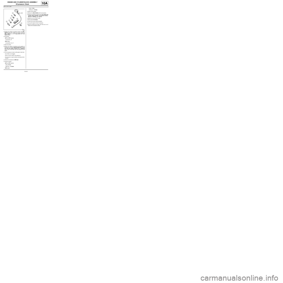
aPosition the engine oil pressure sensor tool (Mot.
836-05) fitted with suitable end pieces using the
(Mot. 1495-01) or a 1/2" long socket (12.7 mm
square drive).
aEnd pieces:
-D4F and D7F engines:
•end piece C + F
-K9K engine:
•end piece E + C + F
aStart the vehicle.
aMonitor the engine oil pressure as the engine oil
temperature increases (approximately 80˚C or the
first time the engine cooling fan is triggered)
which must not be lower than the pressure at idle
speed.
aIf the oil pressure is lower at idle speed, check that:
-the oil filter is not clogged,
-there is no dirt or swarf in the engine oil,
-the oil pump is in good condition and being correct-
ly driven.
aCheck the oil pressure at 3000 rpm.
aCheck the values:
-D4F and D7F engines:
•Idling: 0.8 bar
•3000 rpm: < 3.5 bars
-K9K engine•idling: 1.2 bar
•3000 rpm: < 3.5 bars
aSwitch off the engine.
aRemove the (Mot. 836-05) with the end pieces.
aRefit the oil pressure sensor (see 10A, Engine and
cylinder block assembly, Oil pressure sensor:
Removal - Refitting, page 10A-45) .
aWipe any oil run-off with a cloth.
aWait at least 10 minutes.
aCheck the oil level using the dipstick.
aTop up the engine oil level if necessary.
aStart the vehicle and check that there are no oil
leaks at the oil pressure sensor.
87363
Page 67 of 652
10A-61
ENGINE AND CYLINDER BLOCK ASSEMBLY
Oil pressure: Check
K4M
10A
Oil pressure tables:
End pieces to be used:
I - REMOVAL PREPARATION OPERATION
a
II - CHECK
aRemove the oil pressure sensor (see 10A, Engine
and cylinder block assembly, Oil pressure sen-
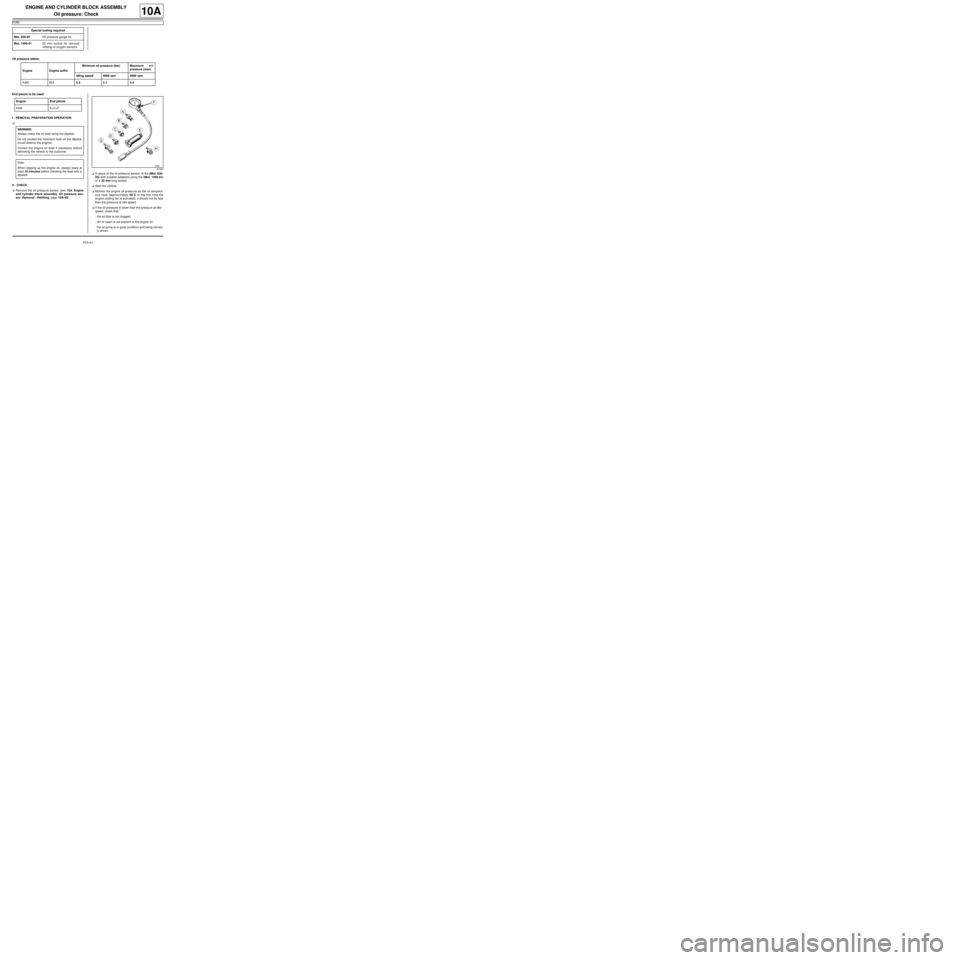
sor: Removal - Refitting, page 10A-45) .aIn place of the oil pressure sensor, fit the (Mot. 836-
05) with suitable adapters using the (Mot. 1495-01)
or a 22 mm long socket.
aStart the vehicle.
aMonitor the engine oil pressure as the oil tempera-
ture rises (approximately 80˚C or the first time the
engine cooling fan is activated); it should not be less
than the pressure at idle speed.
aIf the oil pressure is lower than the pressure at idle
speed, check that:
-the oil filter is not clogged,
-dirt or swarf is not present in the engine oil,
-the oil pump is in good condition and being correct-
ly driven. Special tooling required
Mot. 836-05Oil pressure gauge kit.
Mot. 1495-0122 mm socket for removal -
refitting of oxygen sensors.
Engine Engine suffixMinimum oil pressure (bar) Maximu m o i l
pressure (max)
Idling speed 4000 rpm 4000 rpm
K4M 8540.5 3.1 4.4
Engine End pieces
K4M E+C+F
WARNING
Always check the oil level using the dipstick.
Do not exceed the maximum level on the dipstick
(could destroy the engine).
Correct the engine oil level if necessary before
delivering the vehicle to the customer.
Note:
When topping up the engine oil, always leave at
least 10 minutes before checking the level with a
dipstick.
87363
Page 68 of 652
10A-62
ENGINE AND CYLINDER BLOCK ASSEMBLY
Oil pressure: Check
K4M
10A
aCheck the oil pressure in comparison with the values
given in the table above.
aSwitch off the engine.
aRemove the (Mot. 836-05) with the end pieces.
aRefit the oil pressure sensor (see 10A, Engine and
cylinder block assembly, Oil pressure sensor:
Removal - Refitting, page 10A-45) .
aWipe any oil run-off with a cloth.
aWait at least 10 minutes.
aCheck the oil level using the dipstick.
aTop up the oil level if necessary (see Engine oil:
Specifications) (Technical Note 6013A, 04A, Lubri-
cants).
aStart the vehicle and check that there are no oil
leaks at the oil pressure sensor.
Page 75 of 652
10A-69
ENGINE AND CYLINDER BLOCK ASSEMBLY
Multifunction support: Removal - Refitting
D4F, and 780 or 782
10A
REMOVAL
I - REMOVAL PREPARATION OPERATION
aPosition the vehicle on a two-post lift (see Vehicle:
Towing and lifting) (02A, Lifting equipment).
aDisconnect the battery (see ) (80A, Battery).
aRemove:
-the front right-hand wheel (see Wheel: Removal -
Refitting) (35A, Wheels and tyres),
-the front right-hand wheel arch liner (see Front
wheel arch liner: Removal - Refitting) (55A, Ex-
terior protection),
-the accessories belt (see 11A, Top and front of
engine, Accessories belt: Removal - Refitting,
page 11A-3) ,
-the alternator (see 16A, Starting - Charging, Al-
ternator: Removal - Refitting, page 16A-1) .
aRemove the air conditioning compressor (see Com-
pressor: Removal - Refitting) (62A, Air condition-
ing).II - OPERATION FOR REMOVAL OF PART
CONCERNED
aRemove:
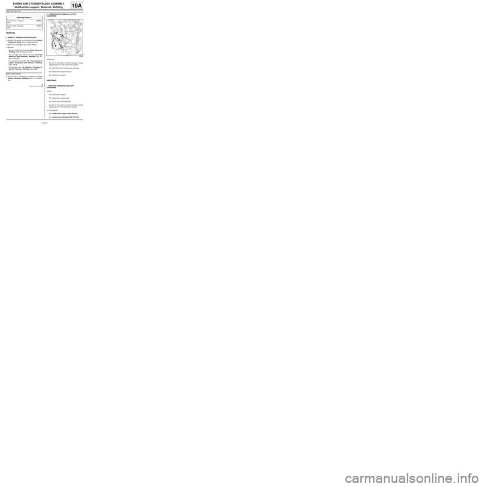
-the bolt of the coolant-oil heat exchanger cooling
pipes support from the multifunction support,
-the bolts (4) from the coolant pump inlet pipe,
-the multifunction support bolts (3) ,
-the multifunction support.
REFITTING
I - REFITTING OPERATION FOR PART
CONCERNED
aRefit:
-the multifunction support,
-the multifunction support bolts,
-the coolant pump inlet pipe bolts,
-the bolt of the coolant-oil heat exchanger cooling
pipes support on the multifunction support.
aTorque tighten:
-the multifunction support bolts (50 N.m),
-the coolant pump inlet pipe bolts (10 N.m). Tightening torquesm
multifunction support
bolts50 N.m
coolant pump inlet pipe
bolts10 N.m
AIR CONDITIONING
120956
Page 83 of 652
10A-77
ENGINE AND CYLINDER BLOCK ASSEMBLY
Engine - gearbox assembly: Removal - Refitting
D4F or D7F
10A
a
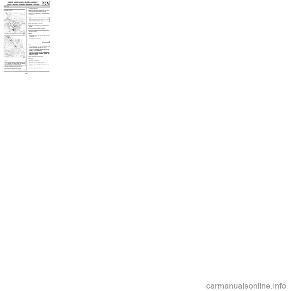
aUndo the clip from the intercooler outlet pipe.
aDisconnect the intercooler outlet air pipe.
aRemove the turbocharger air outlet rigid pipe bolt (9)from the throttle valve.
aDetach the turbocharger air outlet pipe from the tur-
bocharger in the direction of the arrow (10) .
aDisconnect the turbocharger air outlet pipe from the
turbocharger.
aUnclip the intercooler air inlet pipe.
aDisconnect the intercooler air inlet pipe from the in-
tercooler.
aRemove the turbocharger air outlet pipe.
aDisconnect the air filter box air inlet pipe from the air
filter box cover (12) .
aRemove:
-the air filter unit air inlet pipe bolt from the cross
member (13) ,
-the air filter unit air inlet pipe.
aDrain:
-the cooling system (see 19A, Cooling, Cooling
system: Draining - Refilling, page 19A-9) ,
-the gearbox (see Manual gearbox oils: Draining -
Filling) (21A, Manual gearbox),
-the engine if necessary (see 10A, Engine and cyl-
inder block assembly, Engine oil: Draining - Re-
filling, page 10A-22) .
aAttach the cooling unit to the engine.
aDisconnect:
-the heater matrix hoses,
-the brake servo pipe on the brake servo,
-the petrol vapour rebreathing solenoid valve con-
nector,
-the petrol vapour rebreather pipe. D4F, and 780 or 782
122833
122673
Note:
If the turbocharger outlet air pipe tightening clip
(7) is removed, the rubber flexible pipe (8) and
the tightening clip (7) must be replaced.
Note:
If the clip (11) is removed from the heat resistant
protector, the latter must be replaced.
Page 88 of 652
10A-82
ENGINE AND CYLINDER BLOCK ASSEMBLY
Engine - gearbox assembly: Removal - Refitting
D4F or D7F
10A
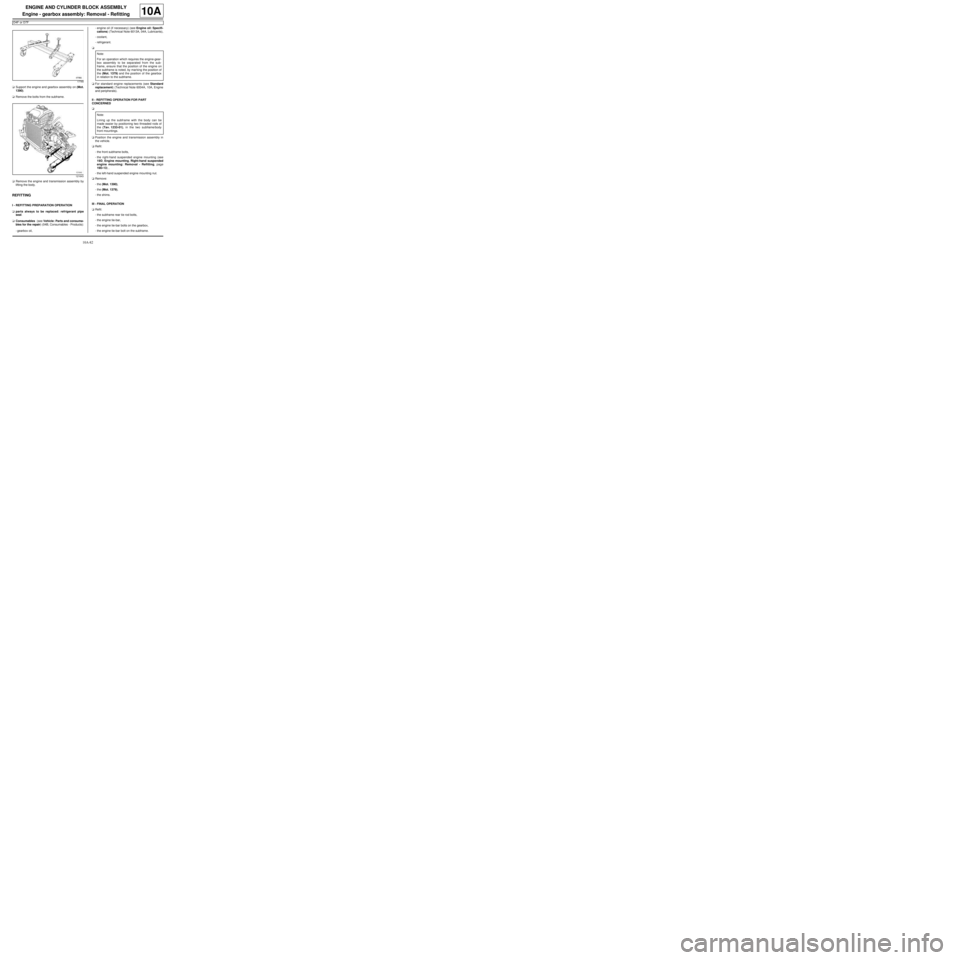
aSupport the engine and gearbox assembly on (Mot.
1390).
aRemove the bolts from the subframe.
aRemove the engine and transmission assembly by
lifting the body.
REFITTING
I - REFITTING PREPARATION OPERATION
aparts always to be replaced: refrigerant pipe
seal.
aConsumables (see Vehicle: Parts and consuma-
bles for the repair) (04B, Consumables - Products):
-gearbox oil,-engine oil (if necessary) (see Engine oil: Specifi-
cations) (Technical Note 6013A, 04A, Lubricants),
-coolant,
-refrigerant.
a
aFor standard engine replacements (see Standard
replacement) (Technical Note 6004A, 10A, Engine
and peripherals).
II - REFITTING OPERATION FOR PART
CONCERNED
a
aPosition the engine and transmission assembly in
the vehicle.
aRefit:
-the front subframe bolts,
-the right-hand suspended engine mounting (see
19D, Engine mounting, Right-hand suspended
engine mounting: Removal - Refitting, page
19D-13) ,
-the left-hand suspended engine mounting nut.
aRemove:
-the (Mot. 1390),
-the (Mot. 1379),
-the shims.
III - FINAL OPERATION
aRefit:
-the subframe rear tie rod bolts,
-the engine tie-bar,
-the engine tie-bar bolts on the gearbox,
-the engine tie-bar bolt on the subframe.
17765
121643
Note:
For an operation which requires the engine-gear-
box assembly to be separated from the sub-
frame, ensure that the position of the engine on
the subframe is noted, by mar king the position of
the (Mot. 1379) and the position of the gearbox
in relation to the subframe .
Note:
Lining up the subframe with the body can be
made easier by positioning two threaded rods of
the (Tav. 1233-01), in the two subframe/body
front mountings.
Page 90 of 652
10A-84
ENGINE AND CYLINDER BLOCK ASSEMBLY
Engine - gearbox assembly: Removal - Refitting
D4F or D7F
10A
aRefit:
-the air conditioning pipe bolt on the dehydrator res-
ervoir,
-the air conditioning pipe bolts on the compressor.
aTighten:
-the air conditioning pipe bolts on the dehydrator
reservoir,
-the air conditioning pipe bolts on the compressor.
aFill the refrigerant circuit (see Refrigerant circuit:
Draining - Filling) (62A, Air conditioning).
aConnect:
-the petrol vapour rebreathing solenoid valve con-
nector,
-the brake servo pipe on the brake servo,
-the heater matrix hoses.
aFit the cooling unit.
aRefill:
-the engine oil, if necessary (see 10A, Engine and
cylinder block assembly, Engine oil: Draining -
Refilling, page 10A-22) ,
-the gearbox oil (see Manual gearbox oils: Drain-
ing - Filling) ,
-and bleed the cooling system (see 19A, Cooling,
Cooling system: Draining - Refilling, page 19A-
9) .
aRefit:
-the air filter unit air inlet pipe,
-the air filter unit air inlet pipe bolt on the cross
member.
aConnect the air filter box air inlet pipe on the air filter
box cover.
aRefit the turbocharger outlet air pipe.
aPush the intercooler air inlet pipe clip.
aConnect the intercooler air inlet pipe on the inter-
cooler.aPush the turbocharger outlet air pipe clip, following
the direction shown by the arrow (23) .
aConnect the turbocharger air outlet pipe onto the tur-
bocharger.
aRefit the turbocharger outlet rigid air pipe bolt on the
throttle valve.
aConnect the intercooler air outlet pipe to the inter-
cooler.
aTighten the intercooler air outlet pipe clip.
aRefit:
-the cooling radiator upper bolts.
-the air filter unit air inlet pipe,
-the air filter box air inlet pipe on the cross member,
aPosition the expansion bottle.
aRefit the expansion bottle bolt.
aClip the bonnet opening release cable on to the cool-
ing fan assembly.
aPosition the earth straps.
aRefit the earth strap nuts on the front right-hand side
member. D4F, and 780 or 782
122666
D4F or D7F, and 772
Page 93 of 652
10A-87
ENGINE AND CYLINDER BLOCK ASSEMBLY
Engine - gearbox assembly: Removal - Refitting
K9K
10A
-the front bumper (see Front bumper: Removal -
Refitting) (55A, Exterior protection).
aDrain:
-the gearbox (see Sequential gearbox oil: Drain-
ing - Filling) (21A, Manual gearbox),
-the engine cooling system (see 19A, Cooling,
Cooling system: Draining - Refilling, page 19A-
9) ,
-the engine, if necessary (see 10A, Engine and
cylinder block assembly, Engine oil: Draining -
Refilling, page 10A-22) ,
-the refrigerant circuit using a refrigerant charging
station (see Refrigerant circuit: Draining - Fill-
ing) (62A, Air conditioning) (if fitted).
aLoosen the clip (5) on the intercooler air outlet pipe.
aPull the clip (6) of the intercooler air inlet pipe.
aDisconnect:
-the intercooler air outlet pipe,
-the intercooler air inlet pipe.
aAttach the « engine cooling radiator - condenser -
intercooler » assembly to the front upper cross
member using a safety strap(s).aAttach the « engine cooling radiator - condenser »
assembly to the front upper cross member.
aRemove:
-the lower engine tie-bar (see 19D, Engine mount-
ing, Lower engine tie-bar: Removal - Refitting,
page 19D-18) ,
-the front axle subframe (see Front axle subframe:
Removal - Refitting) (31A, Front axle compo-
nents),
-the radiator mounting cross member (see Radiator
mounting cross member: Removal - Refitting)
(41A, Front lower structure),
-the front left-hand wheel driveshaft (see Front left-
hand driveshaft: Removal - Refitting) (29A,
Driveshafts),
-the front right-hand wheel driveshaft (see Front
right-hand driveshaft: Removal - Refitting)
(29A, Driveshafts),
-the front section of the intermediate pipe (see 19B,
Exhaust, Intermediate pipe: Removal - Refit-
ting, page 19B-28) . K9K, and 718
122830
K9K, and 740
Page 99 of 652
10A-93
ENGINE AND CYLINDER BLOCK ASSEMBLY
Engine - gearbox assembly: Removal - Refitting
K9K
10A
II - FINAL OPERATION
aRemove the.
aLubricate the seals using recommended air condi-
tioning oil to make fitting easier.
aRefit:
-the connecting pipes to the compressor,
-the connecting pipe union bolts on the compressor,
-the bolt for the connecting pipe mounting on the
compressor.
aConnect:
-the pressostat connector,
-the hose to the coolant pump inlet pipe using the
tool (Mot. 1448).
aFit:
-the hose clip on the coolant pump inlet pipe using
the tool (Mot. 1448),
-the earth on the front left-hand wing.
aRefit the earth nut on the front left-hand wing.
aClip:
-the engine compartment connection unit relay
plates,
-the fuse holders.
aRefit the fuses.
aConnect the preheating unit connector.
aRefit the earth nut on the front left-hand side mem-
ber.
aFit the engine compartment connection unit.
aRefit the engine compartment connection unit
mountings on the body.
aConnect the black connector.
aClip on the black connector.
aRefit:
-the engine compartment connection unit cover,
-a new clip on the battery mounting to hold the elec-
trical wiring.
aConnect the wiring connectors to the fan assembly.aClip the fan assembly wiring.
aRemove the blanking plugs.
aConnect the high pressure pump inlet pipe.
aClip on the fuel supply pipe.
aConnect the high pressure pump return pipe.
aClip on the fuel return pipe.
aRemove the blanking plugs on the clutch hydraulic
control and on the control pipe.
aConnect the clutch hydraulic control to the gearbox.
aClip:
-the clutch control hydraulic pipe on the gearbox,
-the gearbox controls on the cable sleeve stops,
-the gearbox controls on the gear selectors.
aConnect:
-the hoses to the heater radiator,
-the top hose to the water chamber.
aFit:
-the hose clips on the heater radiator using the tool
(Mot. 1448),
-the clip for the top hose on the water chamber us-
ing the tool (Mot. 1448).
aRefit:
-the front section of the intermediate pipe (see 19B,
Exhaust, Intermediate pipe: Removal - Refit-
ting, page 19B-28) ,
-the front right-hand wheel driveshaft (see Front
right-hand driveshaft: Removal - Refitting)
(29A, Driveshafts),
-the front left-hand wheel driveshaft (see Front left-
hand driveshaft: Removal - Refitting) (29A,
Driveshafts),
-the radiator mounting cross member (see Radiator
mounting cross member: Removal - Refitting)
(41A, Front lower structure),
-the front axle subframe (see Front axle subframe:
Removal - Refitting) (31A, Front axle compo-
nents),
-the engine tie-bar (see 19D, Engine mounting,
Lower engine tie-bar: Removal - Refitting, page
19D-18) . WARNING
To prevent any leaks, check that the seal and the
surface of the pipe are in good condition. The
seal and the surface must be clean and scratch
free.