Valve RENAULT TWINGO 2009 2.G Engine And Peripherals Service Manual
[x] Cancel search | Manufacturer: RENAULT, Model Year: 2009, Model line: TWINGO, Model: RENAULT TWINGO 2009 2.GPages: 652
Page 262 of 652

11A-145
TOP AND FRONT OF ENGINE
Camshaft seal, timing end: Removal - Refitting
K4M
11A
aFit the cover (13) and the collar nut (14) of the (Mot.
1632).
aScrew on the collar nut until the cover touches the
cylinder head.
aRemove:
-the collar nut from the (Mot. 1632),
-the cover from the (Mot. 1632),
-the stud from the (Mot. 1632).
III - FINAL OPERATION
aRefit:
-the camshaft dephaser (see 11A, Top and front of
engine, Camshaft dephaser: Removal - Refit-
ting, page 11A-135) ,
-the timing belt (see 11A, Top and front of engine,
Timing belt: Removal - Refitting, page 11A-27) ,
-the right-hand suspended engine mounting (see
19D, Engine mounting, Right-hand suspended
engine mounting: Removal - Refitting, page
19D-13) ,
-the scoop under the scuttle panel grille (see Scoop
under the scuttle panel grille: Removal - Refit-
ting) (56A, Exterior equipment),
-the scuttle panel grille (see Scuttle panel grille:
Removal - Refitting) (56A, Exterior equipment),
-the windscreen wiper arms (see Windscreen wip-
er arm: Removal - Refitting) (85A, Wiping -
Washing),-the throttle valve (see 12A, Fuel mixture, Throttle
valve: Removal - Refitting, page 12A-20) ,
-the air filter unit (see 12A, Fuel mixture, Air filter
unit: Removal - Refitting, page 12A-13) ,
-the accessories belt (see 11A, Top and front of
engine, Accessories belt: Removal - Refitting,
page 11A-3) ,
-the front upper cross member (see Front upper
cross member: Removal - Refitting) (42A, Upper
front structure),
-the bonnet catch (see Bonnet lock: Removal -
Refitting) (52A, Non-side opening element mecha-
nisms),
-the headlights (see Halogen headlight: Removal
- Refitting) (80B, Headlights),
-the front bumper (see Front bumper: Removal -
Refitting) (55A, Exterior protection),
-the front right-hand wheel arch liner (see Front
wheel arch liner: Removal - Refitting) (55A, Ex-
terior protection),
-the front right-hand wheel (see Wheel: Removal -
Refitting) (35A, Wheels and tyres),
-the engine undertray.
aConnect the battery (see Battery: Removal - Refit-
ting) (80A, Battery).
126222
Page 267 of 652
12A-2
FUEL MIXTURE
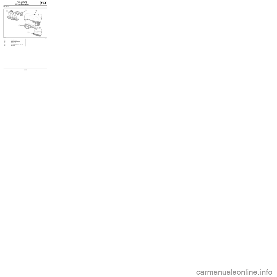
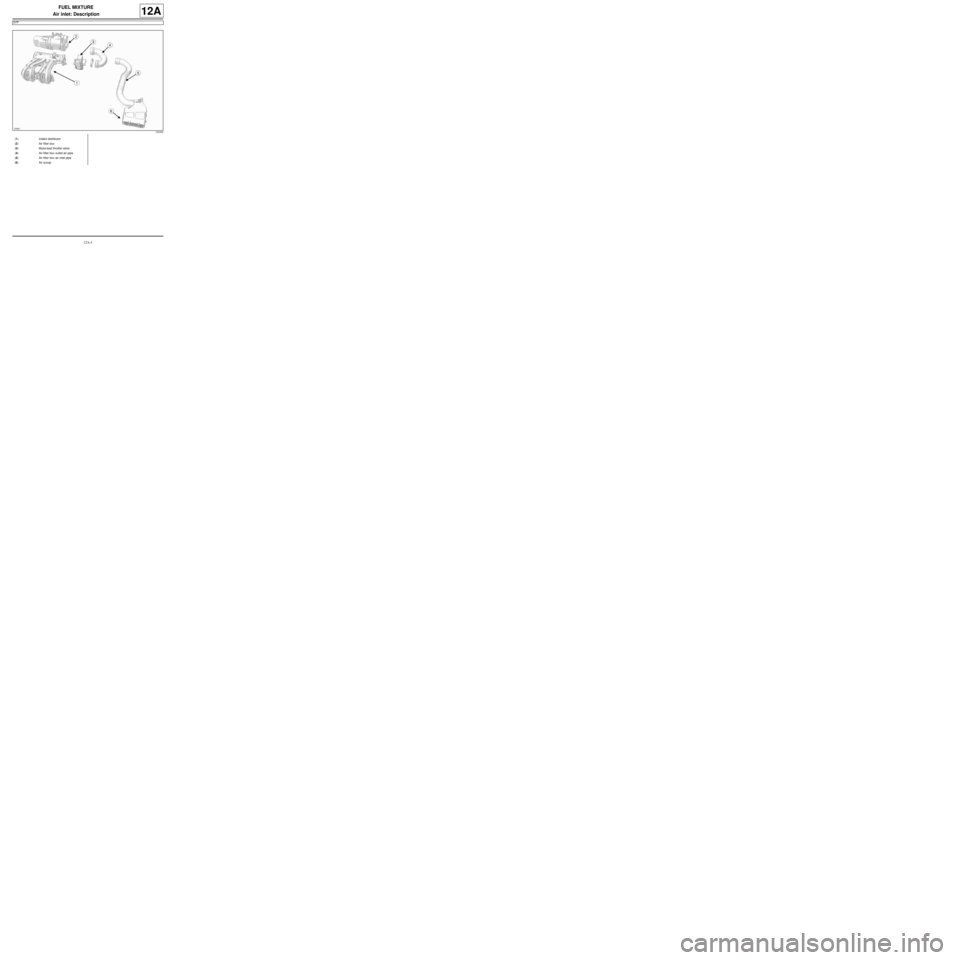
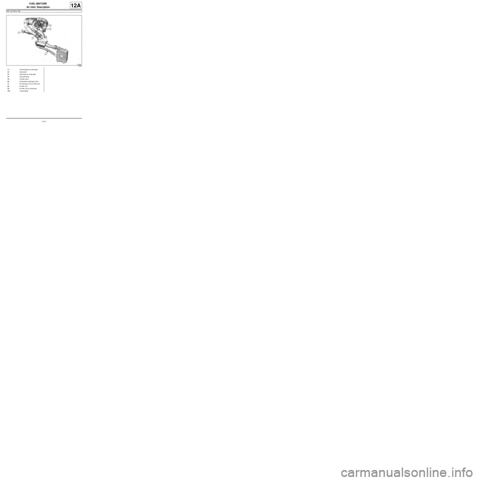
Air inlet: Description
D4F, and 772
12A
120416
(1) Inlet distributor
(2) Motorised throttle valve
(3) Air filter unit
(4) Air inlet pipe of the air fi lter box
(5) Air scoop
Page 268 of 652
12A-3
FUEL MIXTURE
Air inlet: Description
D7F
12A
120402
(1) Intake distributor
(2) Air filter box
(3) Motorised throttle valve
(4) Air filter box outlet air pipe
(5) Air filter box air inlet pipe
(6) Air scoop
Page 269 of 652
12A-4
FUEL MIXTURE
Air inlet: Description
D4F, and 780 or 782
12A
123094
(1) Turbocharger air outlet pipe
(2) Intercooler
(3) Intercooler air outlet pipe
(4) Inlet distributor
(5) Throttle valve
(6) Compressor discharge valve
(7) Air inlet pipe of the air fi lter box
(8) Air filter unit
(9) Air filter unit air outlet pipe
(10) Turbocharger
Page 278 of 652
12A-13
FUEL MIXTURE
Air filter unit: Removal - Refitting
D4F, and 772
12A
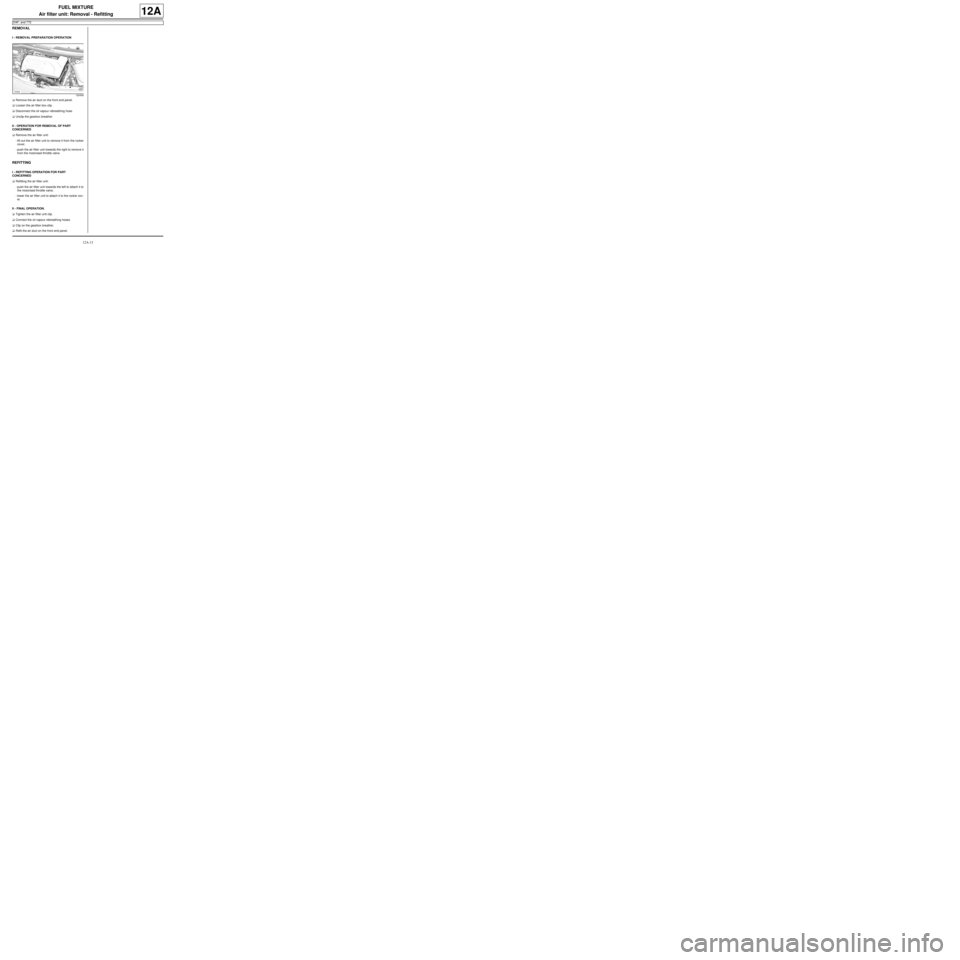
REMOVAL
I - REMOVAL PREPARATION OPERATION
aRemove the air duct on the front end panel.
aLoosen the air filter box clip .
aDisconnect the oil vapour rebreathing hose.
aUnclip the gearbox breather.
II - OPERATION FOR REMOVAL OF PART
CONCERNED
aRemove the air filter unit:
-lift out the air filter unit to remove it from the rocker
cover,
-push the air filter unit towards the right to remove it
from the motorised throttle valve.
REFITTING
I - REFITTING OPERATION FOR PART
CONCERNED
aRefitting the air filter unit:
-push the air filter unit towards the left to attach it to
the motorised throttle valve,
-lower the air filter unit to attach it to the rocker cov-
er.
II - FINAL OPERATION.
aTighten the air filter unit clip.
aConnect the oil vapour rebreathing hoses.
aClip on the gearbox breather.
aRefit the air duct on the front end panel.
120409
Page 281 of 652
12A-16
FUEL MIXTURE
Air filter unit: Removal - Refitting
D7F
12A
PARTS AND CONSUMABLES FOR THE
REPAIR WORK
aParts always to be replaced :
-the air filter.
REMOVAL
I - REMOVAL PREPARATION OPERATION
aRemove the anti-interference wire bolt.
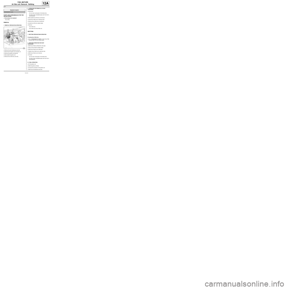
aDisconnect the ignition coil connector (1) .
aRemove the ignition coil bolts (2) .
aMove aside the ignition coil.
aRemove the air filter box cover (3) .II - OPERATION FOR REMOVAL OF PART
CONCERNED
aDisconnect:
-the non-return valve pipe on the brake servo,
-the petrol vapour rebreather pipe union from the in-
take distributor.
aMove aside the air filter box air inlet duct.
aUndo the air filter box air outlet duct clip.
aRemove the air filter box air outlet duct.
aUnclip the air filter box elastic straps.
aRemove:
-the air filter box,
-the air filter from the air filter unit.
REFITTING
I - REFITTING PREPARATIONS OPERATION
If reusing the air filter box
aUse a compressed air nozzle to clean the air filter
housing to get rid of any foreign bodies.
II - REFITTING OPERATION FOR PART
CONCERNED
aRefit the air filter box fitted with a new seal.
aClip on the air filter box elastic straps.
aRefit the air filter box air outlet duct.
aTighten the air filter box air outlet duct clip.
aRefit the air filter box air inlet duct.
aConnect:
-the non-return valve pipe on the brake servo,
-the petrol vapour rebreather pipe union from the in-
take distributor.
III - FINAL OPERATION.
aFit the ignition coil.
aRefit the ignition coil bolts.
aConnect the connector of the ignition coil.
aRefit the anti-interference wire bolt. Equipment required
compressed air nozzle
120404
Page 285 of 652
12A-20
FUEL MIXTURE
Throttle valve: Removal - Refitting
D4F, and 772
12A
REMOVAL
I - REMOVAL PREPARATION OPERATION
aDisconnect the battery (see Battery: Removal - Re-
fitting) (80A, Battery).
aRemove the air filter unit (see 12A, Fuel mixture,
Air filter unit: Removal - Refitting, page 12A-13) .
II - OPERATION FOR REMOVAL OF PART
CONCERNED
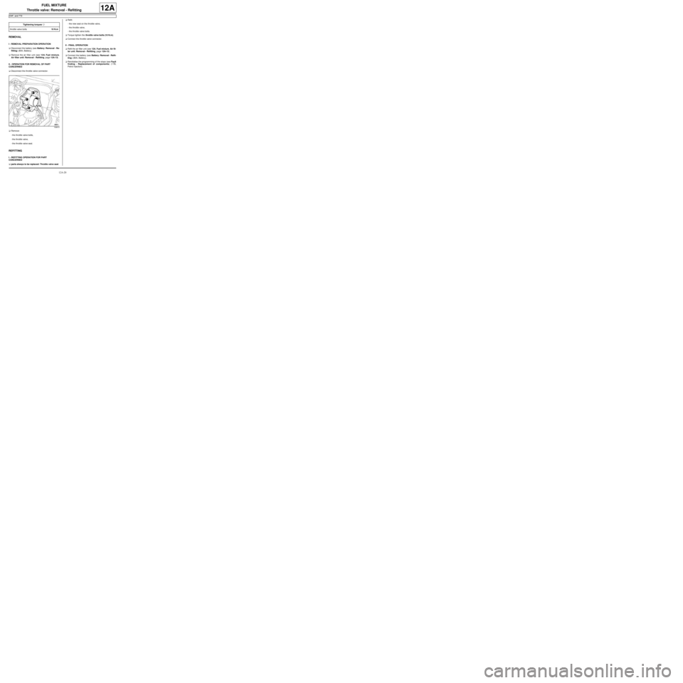
aDisconnect the throttle valve connector.
aRemove:
-the throttle valve bolts,
-the throttle valve,
-the throttle valve seal.
REFITTING
I - REFITTING OPERATION FOR PART
CONCERNED
aparts always to be replaced: Throttle valve seal.aRefit:
-the new seal on the throttle valve,
-the throttle valve,
-the throttle valve bolts.
aTorque tighten the throttle valve bolts (10 N.m).
aConnect the throttle valve connector.
II - FINAL OPERATION
aRefit the air filter unit (see 12A, Fuel mixture, Air fil-
ter unit: Removal - Refitting, page 12A-13) .
aConnect the battery (see Battery: Removal - Refit-
ting) (80A, Battery).
aReinitialise the programming of the stops (see Fault
finding - Replacement of components) (17B,
Petrol injection). Tightening torquesm
throttle valve bolts10 N.m
108810
Page 286 of 652
12A-21
FUEL MIXTURE
Throttle valve: Removal - Refitting
D4F, and 780 or 782
12A
REMOVAL
I - REMOVAL PREPARATION OPERATION
aDisconnect the battery (see ) (80A, Battery).
a
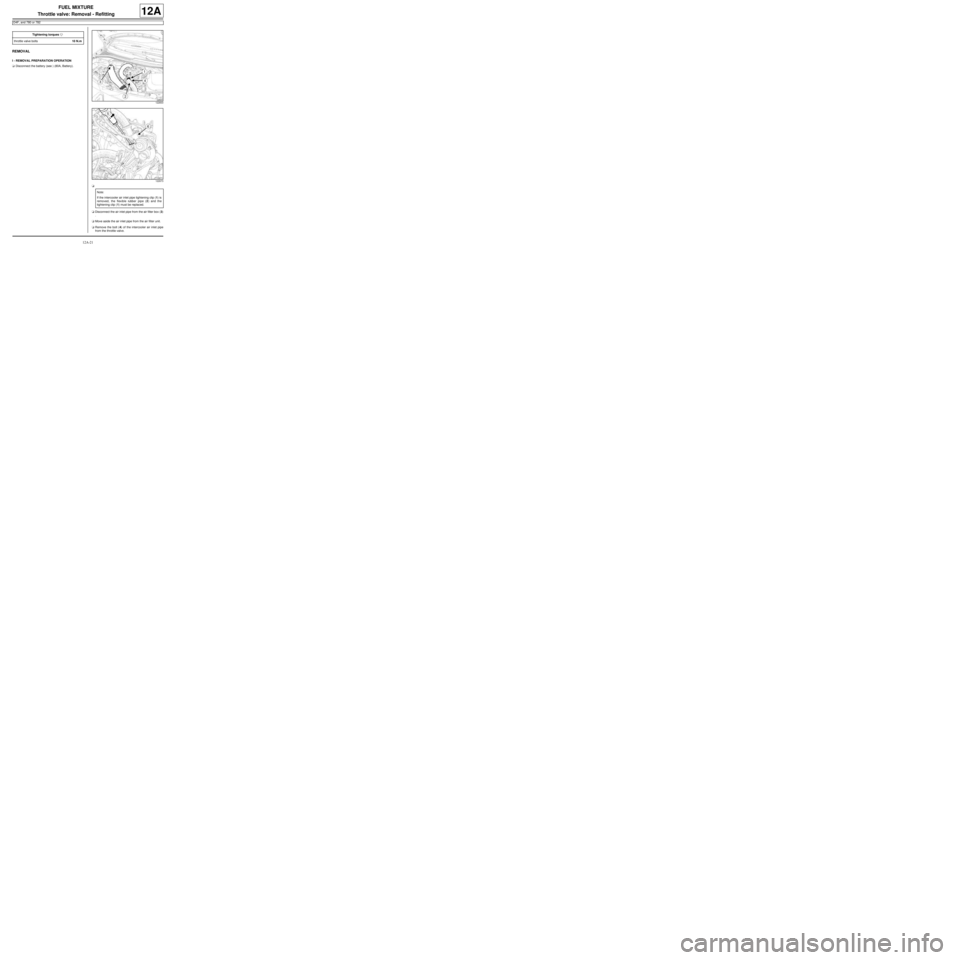
aDisconnect the air inlet pipe from the air filter box (3)
.
aMove aside the air inlet pipe from the air filter unit.
aRemove the bolt (4) of the intercooler air inlet pipe
from the throttle valve. Tightening torquesm
throttle valve bolts10 N.m
122833
122673
Note:
If the intercooler air inlet pipe tightening clip (1) is
removed, the flexible rubber pipe (2) and the
tightening clip (1) must be replaced.
Page 287 of 652
12A-22
FUEL MIXTURE
Throttle valve: Removal - Refitting
D4F, and 780 or 782
12A
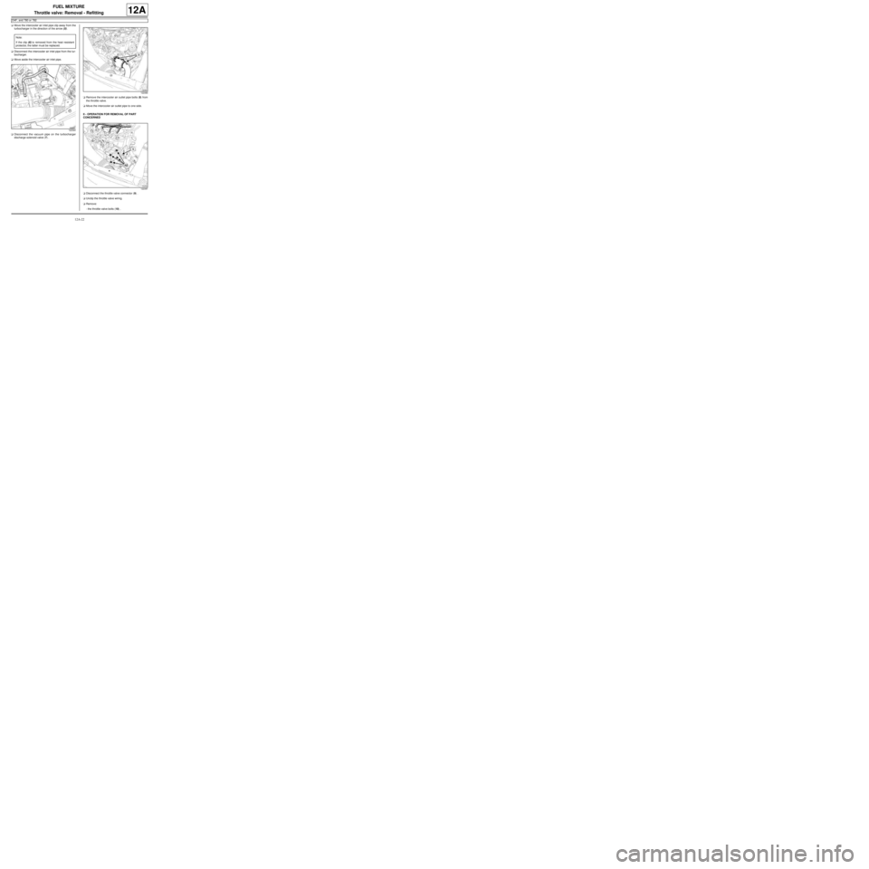
aMove the intercooler air inlet pipe clip away from the
turbocharger in the direction of the arrow (5) .
aDisconnect the intercooler air inlet pipe from the tur-
bocharger.
aMove aside the intercooler air inlet pipe.
aDisconnect the vacuum pipe on the turbocharger
discharge solenoid valve (7) .aRemove the intercooler air outlet pipe bolts (8) from
the throttle valve.
aMove the intercooler air outlet pipe to one side.
II - OPERATION FOR REMOVAL OF PART
CONCERNED
aDisconnect the throttle valve connector (9) .
aUnclip the throttle valve wiring.
aRemove:
-the throttle valve bolts (10) , Note:
If the clip (6) is removed from the heat resistant
protector, the latter must be replaced.
122394
122390
122391
Page 288 of 652

12A-23
FUEL MIXTURE
Throttle valve: Removal - Refitting
D4F, and 780 or 782
12A
-the throttle valve,
-the throttle valve seal.
REFITTING
I - REFITTING PREPARATION OPERATION
aparts always to be replaced: Throttle valve seal.
aUse SURFACE CLEANER (see Vehicle: Parts
and consumables for the repair) (04B, Consuma-
bles - Products) to clean the bearing faces:
-on the inlet distributor,
-on the throttle valve if it is to be reused.
II - REFITTING OPERATION FOR PART
CONCERNED
aRefit:
-a new seal on the throttle valve,
-the throttle valve,
-the throttle valve bolts.
aTorque tighten the throttle valve bolts (10 N.m).
aConnect the throttle valve connector.
aClip the wiring onto the throttle valve.
III - FINAL OPERATION
aRefit:
-the intercooler air outlet pipe on the throttle valve,
-the intercooler air outlet pipe bolts.
aTighten the intercooler air outlet pipe bolts.
aConnect the vacuum pipe onto the turbocharger dis-
charge solenoid valve.aPush the intercooler air inlet pipe clip in the direction
of the arrow (11) .
aFit the intercooler air inlet pipe.
aConnect the intercooler air inlet pipe on the turbo-
charger.
aRefit the intercooler air inlet pipe bolt on the throttle
valve.
aFit the air filter box air inlet pipe.
aConnect:
-the air filter unit air inlet pipe,
-the battery (see ) (80A, Battery).
aProgram the throttle valve (see Fault finding - Re-
placement of components) (17B, Petrol injection).
122666