RENAULT TWINGO RS 2009 2.G Chasiss Workshop Manual
Manufacturer: RENAULT, Model Year: 2009, Model line: TWINGO RS, Model: RENAULT TWINGO RS 2009 2.GPages: 281
Page 171 of 281
36A-20
STEERING ASSEMBLY
Intermediate shaft: Removal - Refitting
36A
II - REFITTING OPERATION FOR PART
CONCERNED
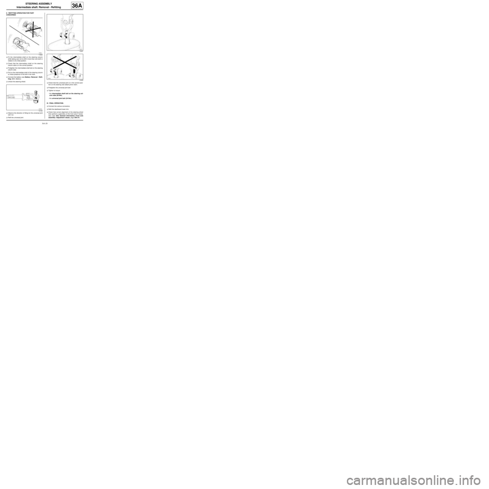
aFit the intermediate shaft on the steering column
while taking care not to shift it more than one tooth in
relation to its initial position.
aCheck that the intermediary shaft on the steering
column side is in the correct position.
aPretighten the intermediate shaft bolt on the steering
column side.
aPull on the intermediate shaft of the steering column
to check presence of the bolt in the neck.
aConnect the battery (see Battery: Removal - Refit-
ting) (80A, Battery).
aUnlock the steering wheel.
aObserve the direction of fitting for the universal joint
cam nut.
aRefit the universal joint.aCheck that the universal joint is in the correct posi-
tion on the steering rack attack pinion stem.
aPretighten the universal joint bolt.
aTighten to torque:
-the intermediate shaft bolt on the steering col-
umn side (29 Nm),
-the universal joint bolt (24 Nm).
III - FINAL OPERATION.
aConnect the various connectors.
aRefit the dashboard lower trim.
aCheck that correct alignment of the steering wheel
then perform a geometry of the front axle if neces-
sary (see 30A, General information, Front axle
assembly: Adjustment values, page 30A-31) .
118922
101354
116021
116022
Page 172 of 281
36A-21
STEERING ASSEMBLY
Steering column adjustment handle: Removal - Refitting36A
REMOVAL
I - REMOVAL PREPARATION OPERATION
aDisconnect the battery (see ) (80A, Battery).
aUnclip the dashboard lower trim.
aDisconnect the various connectors.
aPut the handle in the low position (to prevent the mo-
bile part of the column dropping during dismantling).
aRemove:
-the bolts on the steering wheel lower cover,
-the steering wheel lower cover.II - OPERATION FOR REMOVAL OF PART
CONCERNED
aRemove:
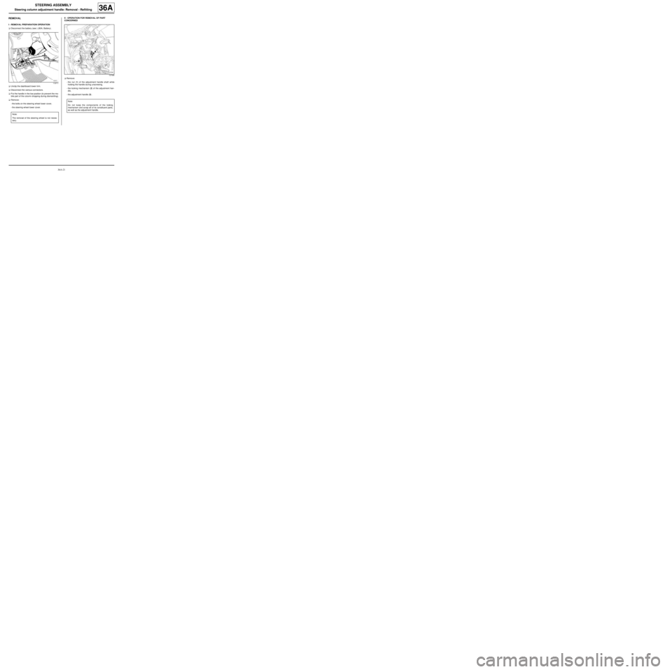
-the nut (1) of the adjustment handle shaft while
holding the handle during unscrewing,
-the locking mechanism (2) of the adjustment han-
dle,
-the adjustment handle (3) .
119711
Note:
The removal of the steering wheel is not neces-
sary.
127586
Note:
Do not keep the components of the locking
mechanism and scrap all of its constituent parts,
as well as the adjustment handle.
Page 173 of 281
36A-22
STEERING ASSEMBLY
Steering column adjustment handle: Removal - Refitting36A
REFITTING
I - REFITTING PREPARATION OPERATION
aII - REFITTING OPERATION FOR PART
CONCERNED
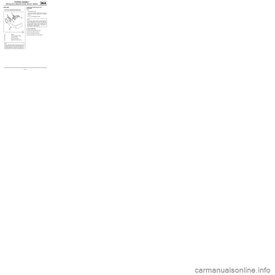
aRefit:
-the adjustment handle,
-the locking mechanism, taking care to correctly in-
dex the cam and the toothed plate in the bracket
opening,
-the nut on the adjustment handle.
III - FINAL OPERATION
aRefit the steering wheel lower cover.
aConnect the various connectors.
aClip on the dashboard lower trim.
aConnect the battery (see ) (80A, Battery).
127583
(4) Handle
(5) Inde xed adjustment plates
(6) Connection shaft
(7) Locking mechanism
(8) Adjustment handle shaft nut
Note:
When refitting the handle, ensure that the retain-
ing spring and the two notched segments are
correctly positioned. Check that the teeth are
interlocked and not in the tooth on tooth position.
Note:
The amount of effort required to operate the han-
dle is determined by how much it is tightened.
Test to determine the correct tightening. The
measurement of effor t must be made with a
torque wrench (Unlocking effort - 10N minimum /
Locking effor t - 60N maximum).
Page 174 of 281
36A-23
STEERING ASSEMBLY
Steering wheel: Removal - Refitting
36A
REMOVAL
I - REMOVAL PREPARATION OPERATION
aApply the procedure for deactivating the safety sys-
tems. (see Airbag and pretensioners: Precau-
tions for the repair)
a
aRemove the driver's front airbag (see Driver's fron-
tal airbag: Removal - Refitting) .
aSet the wheels straight ahead.
aDisconnect the connectors.II - OPERATION FOR REMOVAL OF PART
CONCERNED
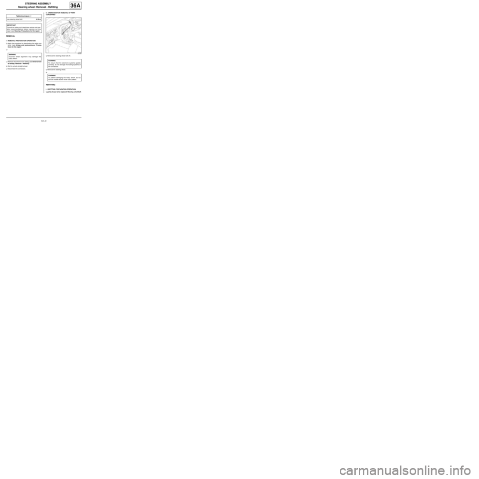
aRemove the steering wheel bolt (1) .
aRemove the steering wheel.
a
REFITTING
I - REFITTING PREPARATION OPERATION
aparts always to be replaced: Steering wheel bolt. Tightening torquesm
new steering wheel bolt44 N.m
IMPORTANT
Consult the safety and cleanliness advice and oper-
ation recommendations before carrying out any
repair (see Steering: Precautions for the repair) .
WARNING
Incorrect wheel alignment may damage the
rotary switch.
122730
WARNING
To ensure that the electronic systems operate
correctly, do not damage the locking systems of
the connectors.
WARNING
To prevent damaging the rotary switch, do not
turn the mobile section of the rotar y switch.
Page 175 of 281
36A-24
STEERING ASSEMBLY
Steering wheel: Removal - Refitting
36A
II - REFITTING OPERATION FOR PART
CONCERNED
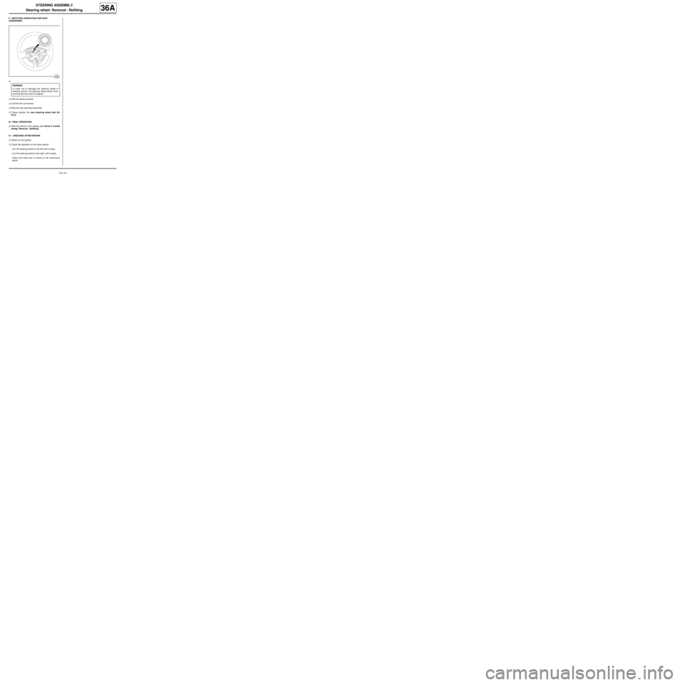
a
aRefit the steering wheel.
aConnect the connectors.
aRefit the new steering wheel bolt.
aTorque tighten the new steering wheel bolt (44
N.m).
III - FINAL OPERATION
aRefit the driver's front airbag (see Driver's frontal
airbag: Removal - Refitting) .
IV - CHECKING AFTER REPAIR
aSwitch on the ignition.
aCheck the operation of the rotary switch:
-turn the steering wheel to the left until it stops,
-turn the steering wheel to the right until it stops,
-check that there are no faults on the instrument
panel.
105327
WARNING
In order not to damage the steering wheel or
steering column, the steering wheel-column fool-
proofing devices must be aligned.
Page 176 of 281
36B-1
POWER ASSISTED STEERING
Power-assisted steering computer: Removal - Refitting
LEFT-HAND DRIVE
36B
REMOVAL
I - REMOVAL PREPARATION OPERATION
aDisconnect the battery (see Battery: Removal - Re-
fitting) (80A, Battery).
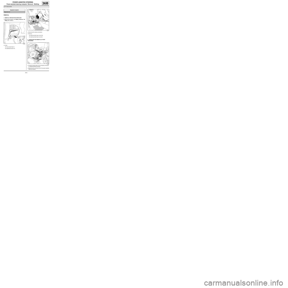
aUnclip:
-the fuse access flap (1) ,
-the dashboard lower trim.aDisconnect the various connectors.
aRemove:
-the steering wheel lower cover bolt,
-the steering wheel lower cover (2) .
II - OPERATION FOR REMOVAL OF PART
CONCERNED
aUnclip the locking clips of the connectors of the pow-
er-assisted steering computer.
aDisconnect the connectors (3) of the power-assisted
steering computer. Equipment required
Diagnostic tool
119506
119711
119858
Page 177 of 281
36B-2
POWER ASSISTED STEERING
Power-assisted steering computer: Removal - Refitting
LEFT-HAND DRIVE
36B
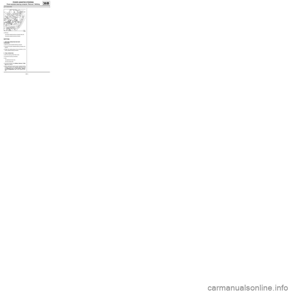
aRemove:
-the power-assisted steering computer bolts (4) ,
-the power-assisted steering computer,
REFITTING
I - REFITTING OPERATION FOR PART
CONCERNED
aRefit the power-assisted steering computer.
aConnect the power-assisted steering computer con-
nectors.
aFasten the locking clips of the connectors of the
power-assisted steering computer.
II - FINAL OPERATION.
aRefit the steering wheel lower cover.
aConnect the various connectors.
aClip:
-the dashboard lower trim,
-the fuse access flap.
aConnect the battery (see Battery: Removal - Refit-
ting) (80A, Battery).
aWhen replacing the electric power-assisted steering
computer, perform the necessary operations using
the Diagnostic tool (see Fault finding - Replace-
ment of components) (36B, Power-assisted steer-
ing).
119882
Page 178 of 281
36B-3
POWER ASSISTED STEERING
Power-assisted steering computer: Removal - Refitting
RIGHT-HAND DRIVE
36B
REMOVAL
I - REMOVAL PREPARATION OPERATION
aDisconnect the battery (see Battery: Removal - Re-
fitting) (80A, Battery).
aUnclip the dashboard lower trim
aDisconnect the various connectors.II - OPERATION FOR REMOVAL OF PART
CONCERNED
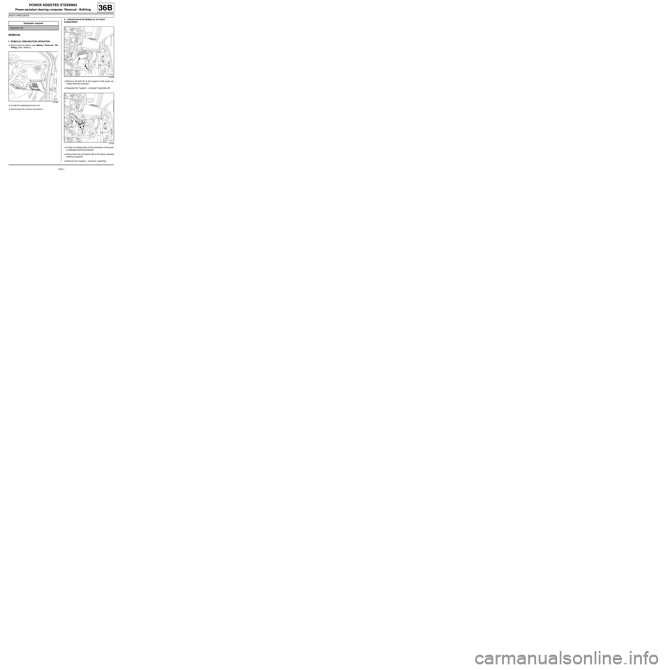
aRemove the bolt (1) of the support of the power-as-
sisted steering computer.
aSeparate the "support - computer" assembly (2) .
aUnclip the locking clips of the connectors of the pow-
er-assisted steering computer.
aDisconnect the connectors (3) of the power-assisted
steering computer.
aRemove the "support - computer" assembly. Equipment required
Diagnostic tool
127585
127588
127589
Page 179 of 281
36B-4
POWER ASSISTED STEERING
Power-assisted steering computer: Removal - Refitting
RIGHT-HAND DRIVE
36B
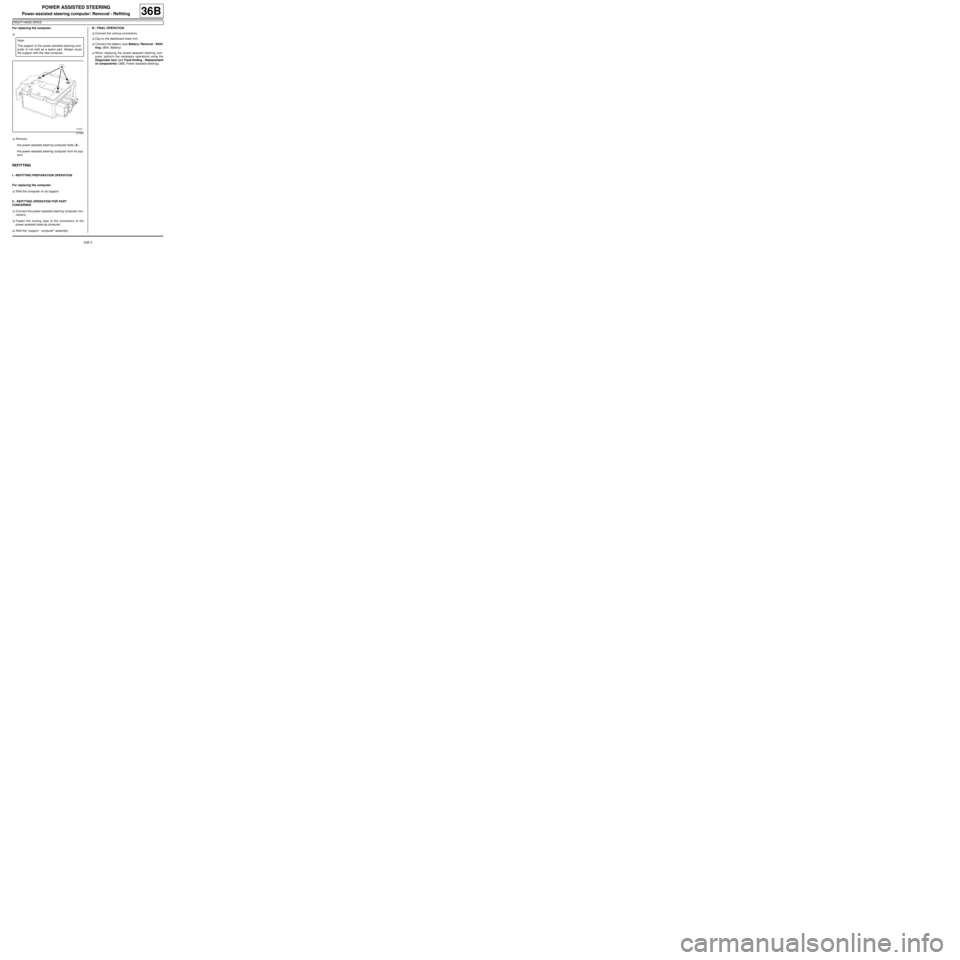
For replacing the computer:
a
aRemove:
-the power-assisted steering computer bolts (4) ,
-the power-assisted steering computer from its sup-
port.
REFITTING
I - REFITTING PREPARATION OPERATION
For replacing the computer:
aRefit the computer on its support.
II - REFITTING OPERATION FOR PART
CONCERNED
aConnect the power-assisted steering computer con-
nectors.
aFasten the locking clips of the connectors of the
power-assisted steering computer.
aRefit the "support - computer" assembly.III - FINAL OPERATION.
aConnect the various connectors.
aClip on the dashboard lower trim.
aConnect the battery (see Battery: Removal - Refit-
ting) (80A, Battery).
aWhen replacing the power-assisted steering com-
puter, perform the necessary operations using the
Diagnostic tool (see Fault finding - Replacement
of components) (36B, Power-assisted steering). Note:
The support of the power-assisted steering com-
puter is not sold as a spare part. Always reuse
the support with the new computer.
127584
Page 180 of 281
37A-1
MECHANICAL COMPONENT CONTROLS
Master cylinder: Removal - Refitting
JB1 or JH1 or JH3 or JR5
37A
REMOVAL
I - REMOVAL PREPARATION OPERATION
aPosition the vehicle on a two-post lift (see Vehicle:
Towing and lifting) (02A, Lifting equipment).
aRemove:
-the battery (see Battery: Removal - Refitting)
(80A, Battery)
-the battery tray (see Battery tray: Removal - Re-
fitting) (80A, Battery).
aRemove:
-the injection computer (see Petrol injection com-
puter: Removal - Refitting) (17B, Petrol injection),
-the injection computer support.II - OPERATION FOR REMOVAL OF PART
CONCERNED
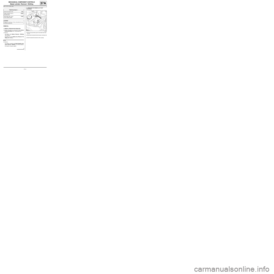
aRemove the fuel filler cap from the brake fluid reser-
voir (1) .
aDisconnect the brake fluid level sensor connector (2)
.
aDrain the brake fluid reservoir with a syringe. Tightening torquesm
brake fluid reservoir bolt4 Nm
master cylinder nuts on
the brake servo25 Nm
rigid brake pipe unions
on the master cylinder15 Nm
WARNING
Prepare for the flow of fluid, and protect the sur-
rounding components.
K4M
121344