wheel bolts RENAULT TWINGO RS 2009 2.G Chasiss Owner's Guide
[x] Cancel search | Manufacturer: RENAULT, Model Year: 2009, Model line: TWINGO RS, Model: RENAULT TWINGO RS 2009 2.GPages: 281
Page 126 of 281
33A-28
REAR AXLE COMPONENTS
Rear suspension spring: Removal - Refitting
33A
REMOVAL
I - REMOVAL PREPARATION OPERATION
aPosition the vehicle on a two-post lift ( (see Vehicle:
Towing and lifting) ).
aRemove the rear wheels (see 35A, Wheels and ty-
res, Wheel: Removal - Refitting, page 35A-1) .
II - OPERATION FOR REMOVAL OF PART
CONCERNED
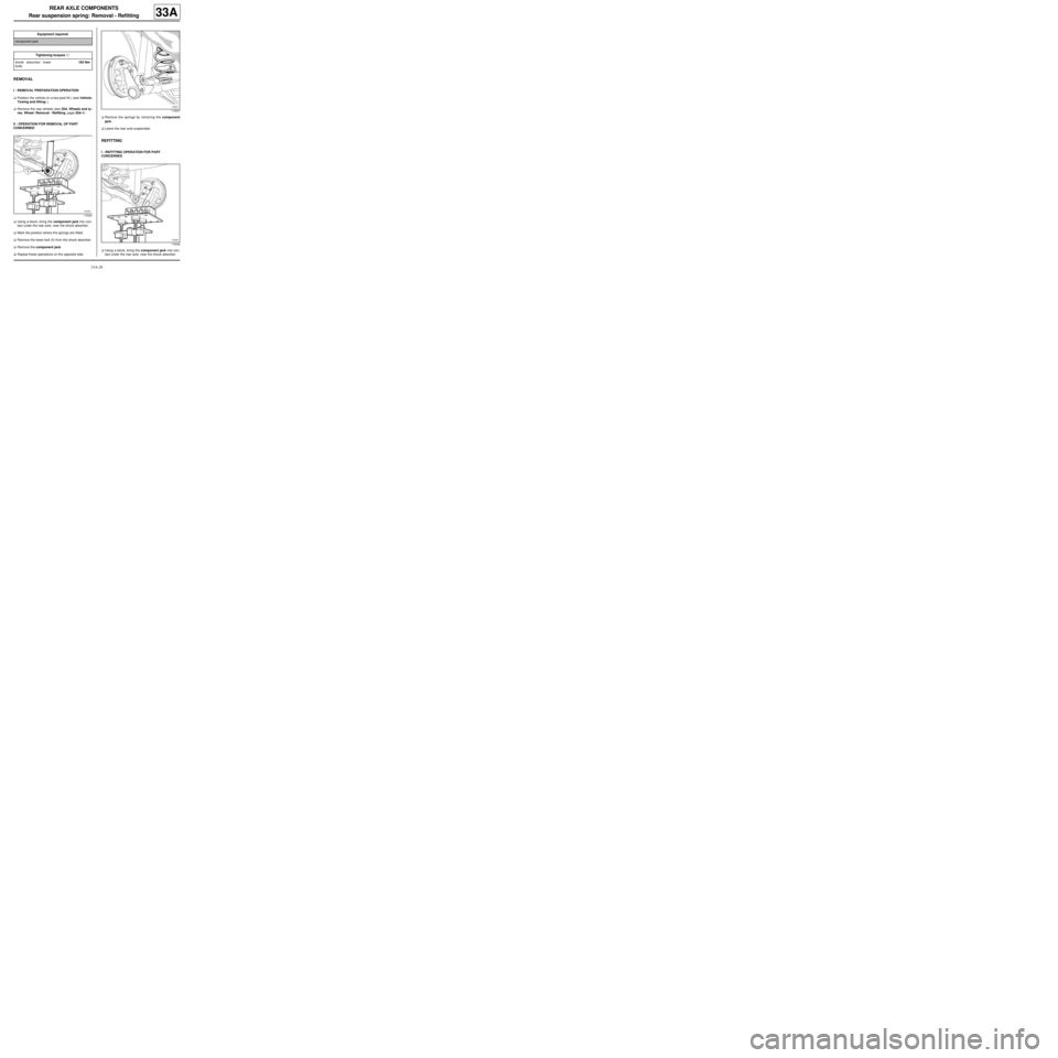
aUsing a block, bring the component jack into con-
tact under the rear axle, near the shock absorber.
aMark the position where the springs are fitted.
aRemove the lower bolt (1) from the shock absorber.
aRemove the component jack.
aRepeat these operations on the opposite side.aRemove the springs by removing the component
jack.
aLeave the rear axle suspended.
REFITTING
I - REFITTING OPERATION FOR PART
CONCERNED
aUsing a block, bring the component jack into con-
tact under the rear axle, near the shock absorber. Equipment required
component jack
Tightening torquesm
shock absorber lower
bolts105 Nm
119340
119547
119546
Page 127 of 281
33A-29
REAR AXLE COMPONENTS
Rear suspension spring: Removal - Refitting
33A
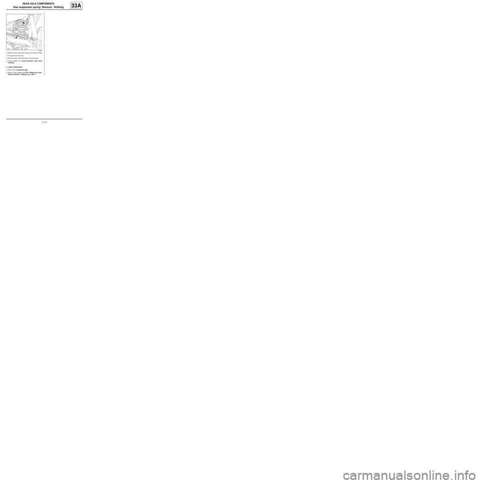
aRefit the shock absorber springs into their housings.
aCompress the rear axle.
aRefit the lower shock absorber mounting bolts.
aTorque tighten the shock absorber lower bolts
(105 Nm).
II - FINAL OPERATION.
aRemove the component jack.
aRefit the rear wheels (see 35A, Wheels and tyres,
Wheel: Removal - Refitting, page 35A-1) .
119400
Page 130 of 281
33A-32
REAR AXLE COMPONENTS
Rear stub axle carrier: Removal - Refitting
33A
REMOVAL
I - REMOVAL PREPARATION OPERATION
aPosition the vehicle on a two-post lift ( (see Vehicle:
Towing and lifting) ).
aRelease the parking brake.
aRemove:
-the rear wheel on the side concerned (see 35A,
Wheels and tyres, Wheel: Removal - Refitting,
page 35A-1) ,
-the brake drum (see 33A, Rear axle components,
Rear brake drum: Removal - Refitting, page
33A-19) .
aFit the component jack to undo the shock absorber
mountings.
aRemove the shock absorber lower bolt.II - OPERATION FOR REMOVAL OF PART
CONCERNED
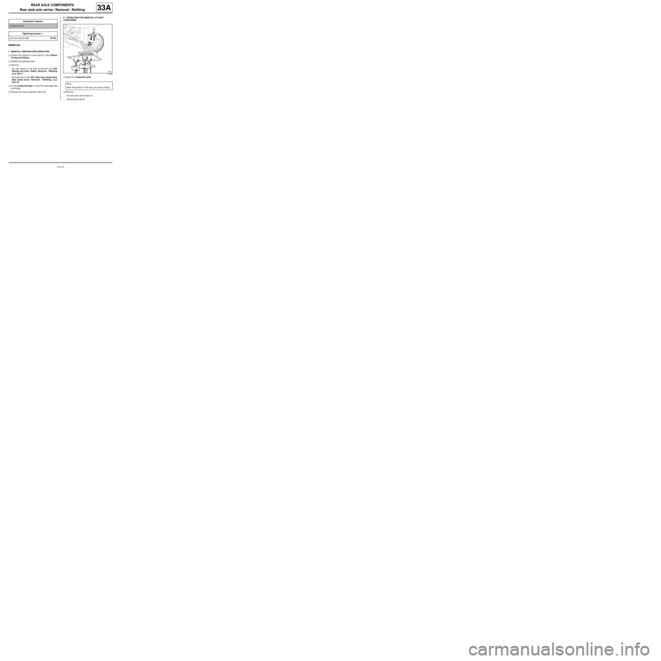
aAdjust the component jack.
aRemove:
-the stub axle carrier bolts (1) ,
-the stub axle carrier. Equipment required
component jack
Tightening torquesm
stub axle carrier bolts53 Nm
119648
Note:
Mar k the position of the stub axle carrier writing.
Page 131 of 281

33A-33
REAR AXLE COMPONENTS
Rear stub axle carrier: Removal - Refitting
33A
REFITTING
I - REFITTING PREPARATIONS OPERATION
aClean the stub axle carrier using the cleaning sta-
tion.
II - REFITTING OPERATION FOR PART
CONCERNED
aRefit:
-the stub axle carrier,
-the stub axle bolts.
aTorque tighten the stub axle carrier bolts (53 Nm).
aRemove the component jack.
III - FINAL OPERATION.
aRefit:
-the brake drum (see 33A, Rear axle components,
Rear brake drum: Removal - Refitting, page
33A-19) ,
-the rear wheel on the side concerned (see 35A,
Wheels and tyres, Wheel: Removal - Refitting,
page 35A-1) .
117348
Page 132 of 281
33A-34
REAR AXLE COMPONENTS
Rear stub axle carrier: Removal - Refitting
EQ UIPMENT LEVEL SPORT
33A
REMOVAL
I - REMOVAL PREPARATION OPERATION
aPosition the vehicle on a two-post lift (see Vehicle:
Towing and lifting) (02A, Lifting equipment).
aRemove the rear wheel (see 35A, Wheels and ty-
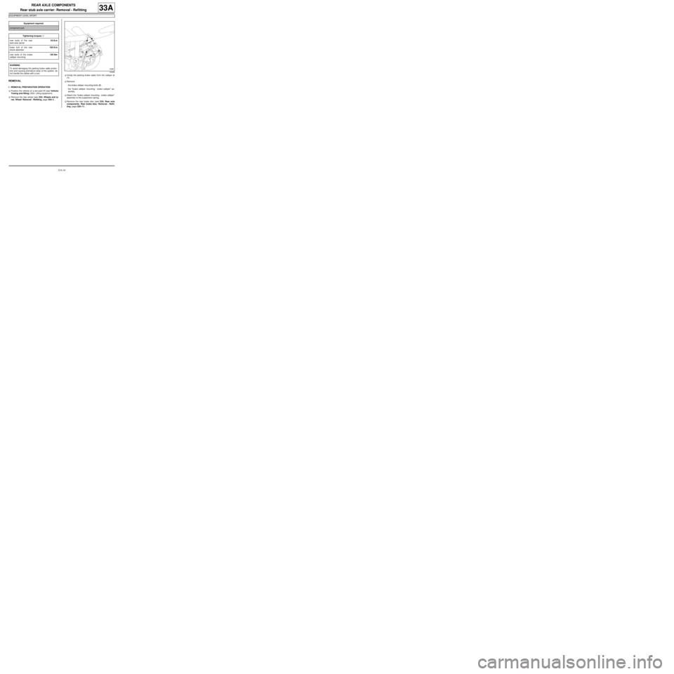
res, Wheel: Removal - Refitting, page 35A-1) .aUnclip the parking brake cable from the calliper at
(1) .
aRemove:
-the brake calliper mounting bolts (2) ,
-the "brake calliper mounting - brake calliper" as-
sembly.
aAttach the "brake calliper mounting - brake calliper"
assembly to the suspension spring.
aRemove the rear brake disc (see 33A, Rear axle
components, Rear brake disc: Removal - Refit-
ting, page 33A-11) . Equipment required
component jack
Tightening torquesm
new bolts of the rear
stub axle carrier53 N.m
lower bolt of the rear
shock absorber105 N.m
new bolts of the brake
calliper mounting105 Nm
WARNING
To avoid damaging the parking brake cable protec-
tors and causing premature wear of the system, do
not handle the cables with a tool.
132468
Page 133 of 281
33A-35
REAR AXLE COMPONENTS
Rear stub axle carrier: Removal - Refitting
EQ UIPMENT LEVEL SPORT
33A
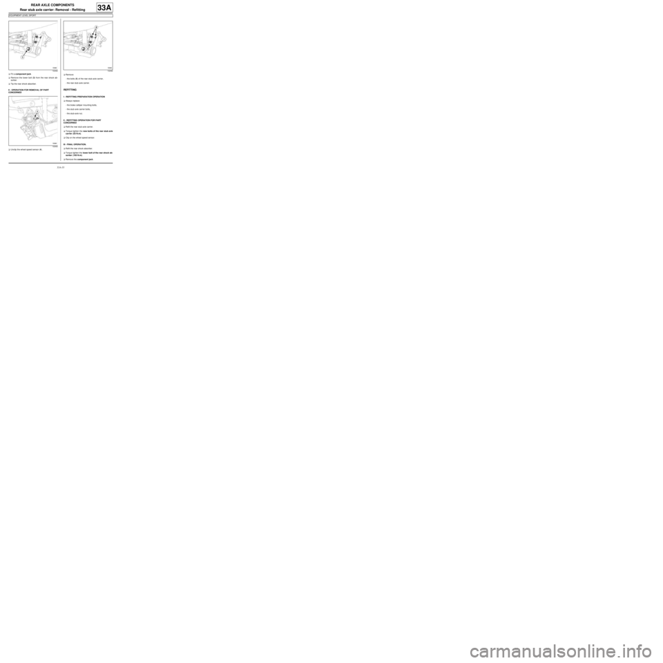
aFit a component jack.
aRemove the lower bolt (3) from the rear shock ab-
sorber.
aTip the rear shock absorber.
II - OPERATION FOR REMOVAL OF PART
CONCERNED
aUnclip the wheel speed sensor (4) .aRemove:
-the bolts (5) of the rear stub axle carrier,
-the rear stub axle carrier.
REFITTING
I - REFITTING PREPARATION OPERATION
aAlways replace:
-the brake calliper mounting bolts,
-the stub axle carrier bolts,
-the stub-axle nut.
II - REFITTING OPERATION FOR PART
CONCERNED
aRefit the rear stub axle carrier.
aTorque tighten the new bolts of the rear stub axle
carrier (53 N.m).
aClip on the wheel speed sensor.
III - FINAL OPERATION.
aRefit the rear shock absorber.
aTorque tighten the lower bolt of the rear shock ab-
sorber (105 N.m).
aRemove the component jack.
132462
132463132462
Page 134 of 281
33A-36
REAR AXLE COMPONENTS
Rear stub axle carrier: Removal - Refitting
EQ UIPMENT LEVEL SPORT
33A
aRefit:
-the brake disc (see 33A, Rear axle components,
Rear brake disc: Removal - Refitting, page 33A-
11) ,
-the "brake calliper mounting - brake calliper" as-
sembly.
aTorque tighten the new bolts of the brake calliper
mounting (105 Nm).
aClip the parking brake cable onto the brake calliper.
aRefit the rear wheel (see 35A, Wheels and tyres,
Wheel: Removal - Refitting, page 35A-1) .
IMPORTANT
To avoid any accident, bring the pistons, brake
pads and brake discs into contact by depressing
the brake pad several times.
Page 135 of 281
33A-37
REAR AXLE COMPONENTS
Complete rear axle system: Removal - Refitting
33A
REMOVAL
I - REMOVAL PREPARATION OPERATION
aPosition the vehicle on a two-post lift ( (see Vehicle:
Towing and lifting) ).
aRelease the parking brake.
aFit the pedal press on the brake pedal to limit the
amount of brake fluid running out.
aRemove the rear wheels (see 35A, Wheels and ty-
res, Wheel: Removal - Refitting, page 35A-1) .II - OPERATION FOR REMOVAL OF PART
CONCERNED
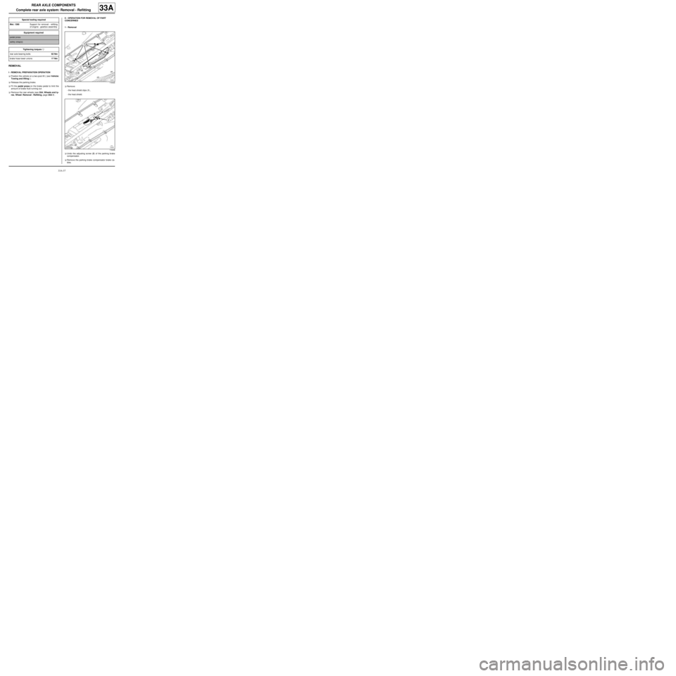
1 - Removal
aRemove:
-the heat shield clips (1) ,
-the heat shield.
aUndo the adjusting screw (2) of the parking brake
compensator.
aRemove the parking brake compensator brake ca-
bles. Special tooling required
Mot. 1390Suppor t for removal - refitting
of engine - gearbox assembly
Equipment required
pedal press
safety strap(s)
Tightening torquesm
rear axle bearing bolts62 Nm
brake hose lower unions17 Nm
119435
119436
Page 140 of 281

33A-42
REAR AXLE COMPONENTS
Complete rear axle system: Removal - Refitting
33A
2 - Refitting
aLower the lift.
aPosition the bearing centring devices (12) opposite
the centring holes.
aRefit the rear axle bearing bolts.
aTorque tighten the rear axle bearing bolts (62 Nm).
aRemove the safety strap(s).
aRaise the lift.
aRefit:
-the rear suspension springs (see 33A, Rear axle
components, Rear suspension spring: Remov-
al - Refitting, page 33A-28) ,
-the brake hose lower unions.
aTorque tighten the brake hose lower unions (17
Nm).
aConnect the ABS sensor connectors.
aClose the ABS sensor connector protective unit.
aClip the parking brake cables onto the reservoir.
aPosition the parking brake cables on the parking
brake compensator.
aCheck that the parking brake cable stops are proper-ly inserted in their housings.
III - FINAL OPERATION.
aAdjust the parking brake cables (see 37A, Mechan-
ical component controls, Parking brake lever:
Removal - Refitting, page 37A-46) .
aRefit the rear wheels (see 35A, Wheels and tyres,
Wheel: Removal - Refitting, page 35A-1) .
aRemove the pedal press.
aBleed the braking circuit (see 30A, General infor-
mation, Braking circuit: Bleed, page 30A-4) .
119651
Page 141 of 281
35A-1
WHEELS AND TYRES
Wheel: Removal - Refitting
35A
The removal - refitting procedure is the same for all
wheels.
REMOVAL
I - REMOVAL PREPARATION OPERATION
aPosition the vehicle on a two-post lift (see Vehicle:
Towing and lifting) (02A, Lifting equipment).
aRelease the parking brake.
aRemove the trim.
aPosition the wheel so that the valve is at the top.
aMark the position of the wheel on the hub.
II - OPERATION FOR REMOVAL OF PART
CONCERNED
aLoosen the wheel bolts with the wheel on the
ground.
aRaise the lift.
aRemove:
-the wheel bolts,
-the wheel.
If the wheel cannot be removed after the bolt has
been undone:
aPosition all the wheel bolts.
aTighten the wheel bolts to bring all the bolt heads
into contact with the wheel.
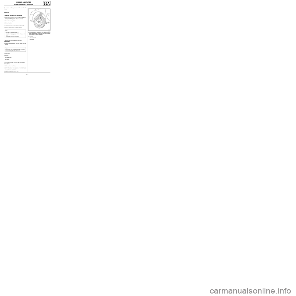
aUndo the wheel bolts by one turn.aStrike around the edge of the tyre walls (1) several
times using a mallet on the inner and outer surfaces
of the wheel to detach the wheel.
aRemove:
-the wheel bolts,
-the wheel. Note:
This mark is required in order to:
-Note the original position of the wheel on the
hub,
-perform the balancing operation.
Note:
Use sockets with protective sheaths in order to
avoid scratching the alloy wheel rims.
100682