wheel bolts RENAULT TWINGO RS 2009 2.G Chasiss Service Manual
[x] Cancel search | Manufacturer: RENAULT, Model Year: 2009, Model line: TWINGO RS, Model: RENAULT TWINGO RS 2009 2.GPages: 281
Page 142 of 281
35A-2
WHEELS AND TYRES
Wheel: Removal - Refitting
35A
If this procedure does not work:
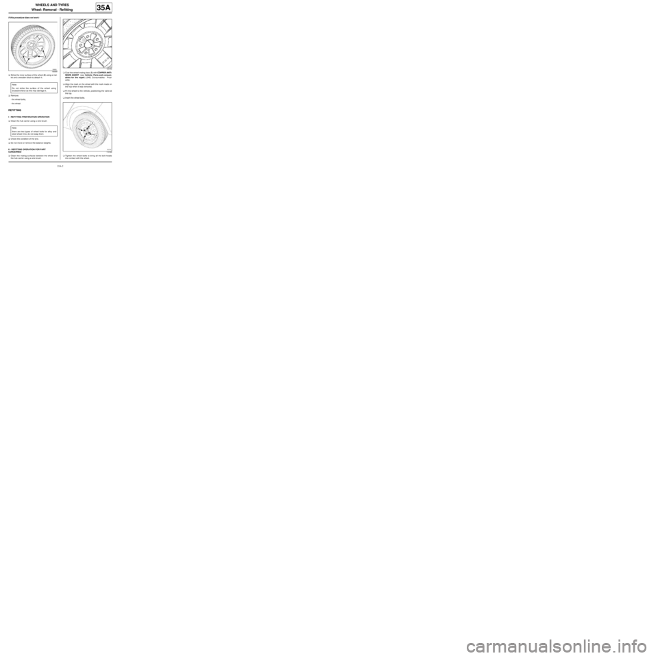
aStrike the inner surface of the wheel (2) using a mal-
let and a wooden block to detach it.
aRemove:
-the wheel bolts,
-the wheel.
REFITTING
I - REFITTING PREPARATION OPERATION
aClean the hub carrier using a wire brush.
aCheck the condition of the tyre.
aDo not move or remove the balance weights.
II - REFITTING OPERATION FOR PART
CONCERNED
aClean the mating surfaces between the wheel and
the hub carrier using a wire brush.aCoat the wheel-mating face (3) with COPPER ANTI-
SEIZE AGENT (see Vehicle: Parts and consum-
ables for the repair) (04B, Consumables - Prod-
ucts).
aAlign the mark on the wheel with the mark made on
the hub when it was removed.
aFit the wheel to the vehicle, positioning the valve at
the top.
aInsert the wheel bolts.
aTighten the wheel bolts to bring all the bolt heads
into contact with the wheel.
106089
Note:
Do not strike the surface of the wheel using
excessive force as this may damage it.
Note:
there are two types of wheel bolts for alloy and
steel wheel rims; do not swap them.
124750
113180
Page 143 of 281
35A-3
WHEELS AND TYRES
Wheel: Removal - Refitting
35A
aPretighten the wheel bolts to 30 N.m, with the wheel
suspended, starting with the bolts at the bottom.
aRotate the wheel through 180˚ to bring the valve into
the bottom position.
aPosition the vehicle on its wheels.
aTorque tighten the wheel bolts in order (see 30A,
General information, Front axle system: Tighten-
ing torque, page 30A-27) (30A, General informa-
tion).
aRefit the trim piece.Note:
Use sockets with protective sheaths in order to
avoid scratching the alloy wheel rims.
Page 151 of 281
35A-11
WHEELS AND TYRES
Wheel rim: Identification
35A
IDENTIFICATION
1 - Marking
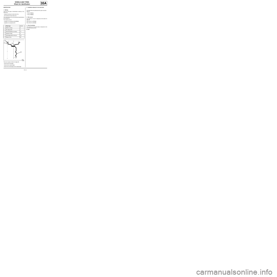
There are two types of identification marking on the
wheel rims:
-engraved marking for steel wheel rims,
-cast marking for alloy wheel rims.
The marking gives the main dimensional specifications
of the wheel rim.
This marking may be:
-complete, for example 6 J 15 5 CH 36,
-simplified, for example 6 J 15.
There are 3 types of wheel rim edges (2) :
-those with two flat edges,
-those with two raised edges,
-those with one flat edge and one raised edge.2 - Installation diameter for the wheel bolts
The wheel bolts are positioned with a pitch circle dia-
meter of:
-5 holes: 108 mm,
-4 holes: 100 mm.
3 - Rim run-out
The maximum run-out is measured at the wheel rim
edge (7) .
Steel wheel rims: 0.8 mm
Alloy wheel rims: 0.3 mm
4 - Out-of-roundness
The maximum out-of-round value is measured on the
tyre bead bearing surface.
0.7 mm Wheel type 6 J 15
1Width (in inches) 6
2Rim edge profile J
3Nominal diameter (in inches) 15
4Number of holes 5
5Anchorage profile of the tyre CH
6Offset (in mm) 36
100988
Page 152 of 281
36A-1
STEERING ASSEMBLY
Steering box: Removal - Refitting
36A
REMOVAL
I - REMOVAL PREPARATION OPERATION
aPosition the vehicle on a two-post lift ( (see Vehicle:
Towing and lifting) ).
aRemove:
-the front wheels (see 35A, Wheels and tyres,
Wheel: Removal - Refitting, page 35A-1) ,
-the front wheel arch liners (see Front wheel arch
liner: Removal - Refitting) (55A, Exterior protec-
tion),
-the « subframe - front driveshaft lower arm - power-
assisted steering box - front anti-roll bar » assem-
bly (see 31A, Front axle components, Front axle
subframe: Removal - Refitting, page 31A-43) .
II - OPERATION FOR REMOVAL OF PART
CONCERNED
aRemove:
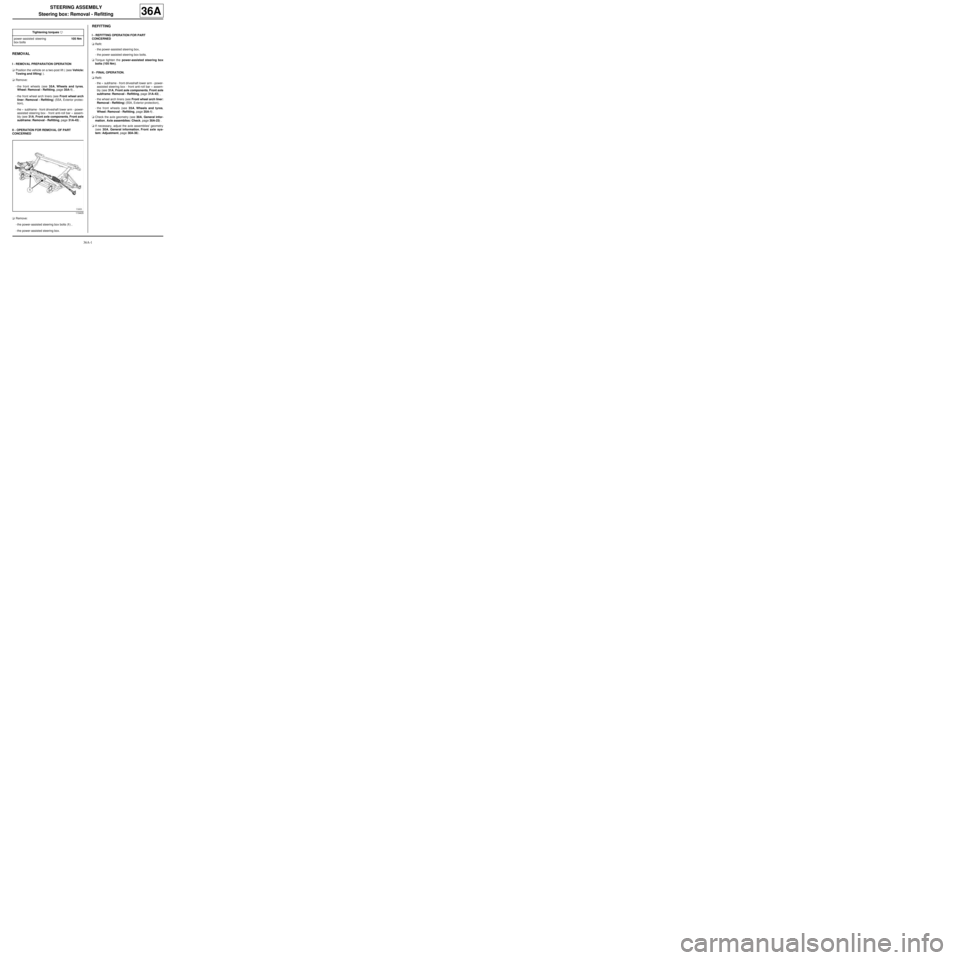
-the power-assisted steering box bolts (1) ,
-the power-assisted steering box.
REFITTING
I - REFITTING OPERATION FOR PART
CONCERNED
aRefit:
-the power-assisted steering box,
-the power-assisted steering box bolts.
aTorque tighten the power-assisted steering box
bolts (105 Nm).
II - FINAL OPERATION.
aRefit:
-the « subframe - front driveshaft lower arm - power-
assisted steering box - front anti-roll bar » assem-
bly (see 31A, Front axle components, Front axle
subframe: Removal - Refitting, page 31A-43) ,
-the wheel arch liners (see Front wheel arch liner:
Removal - Refitting) (55A, Exterior protection),
-the front wheels (see 35A, Wheels and tyres,
Wheel: Removal - Refitting, page 35A-1) .
aCheck the axle geometry (see 30A, General infor-
mation, Axle assemblies: Check, page 30A-23) .
aIf necessary, adjust the axle assemblies' geometry
(see 30A, General information, Front axle sys-
tem: Adjustment, page 30A-36) . Tightening torquesm
power-assisted steering
box bolts105 Nm
119405
Page 158 of 281
36A-7
STEERING ASSEMBLY
Steering column: Removal - Refitting
LEFT-HAND DRIVE
36A
REMOVAL
I - REMOVAL PREPARATION OPERATION
aUnlock the steering column.
aLock the airbag computer using the Diagnostic tool
(see Fault finding - Replacement of components)
(MR 413, 88C, Airbags - Pretensioners).
aDisconnect the battery (see Battery: Removal - Re-
fitting) (MR 411, 80A, Battery).
aSet the wheels straight ahead.
aRemove:
-the driver's front airbag (see Driver's frontal air-
bag: Removal - Refitting) (MR 411, 88C, Airbags
- Pretensioners),
-the steering wheel (see 36A, Steering assembly,
Steering wheel: Removal - Refitting, page 36A-
23) ,-the steering column switch assembly (see Steer-
ing column switch assembly: Removal - Refit-
ting) (MR 411, 84A, Steering column switch
assembly),
-the immobiliser antenna/transponder ring (see
Transponder ring: Removal - Refitting) (MR
411, 82A, Immobiliser),
-the ignition switch if the steering column is replaced
(see Ignition switch: Removal - Refitting) (MR
411, 82A, Immobiliser).
II - REMOVAL OPERATION FOR PART
CONCERNED
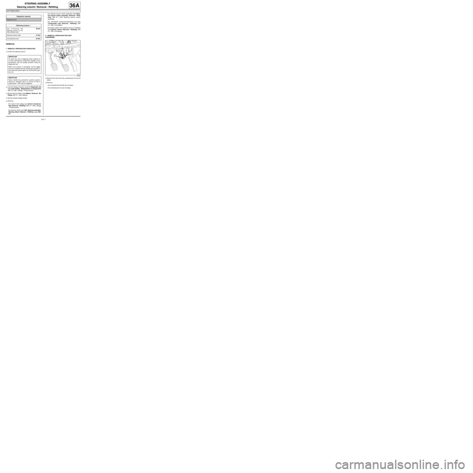
aRemove the cover from the universal joint (1) (do not
keep).
aRemove:
-the universal joint bolt (2) (do not keep),
-the universal joint nut (do not keep). Equipment required
Diagnostic tool
Tightening torquesm
bolt connecting the
steering column to the
inter mediate shaft30 Nm
steer ing column bolts21 Nm
universal joint bolt24 Nm
IMPORTANT
To avoid any risk of triggering when working on
or near a pyrotechnic component (airbags or pre-
tensioners), lock the airbag computer using the
diagnostic tool.
When this function is activated, all the trigger
lines are inhibited and the airbag warning light on
the instrument panel lights up continuously (igni-
tion on).
IMPORTANT
Never handle the pyrotechnic systems (preten-
sioners or airbags) near to a source of heat or
naked flame - they may be triggered.
119544
Page 159 of 281
36A-8
STEERING ASSEMBLY
Steering column: Removal - Refitting
LEFT-HAND DRIVE
36A
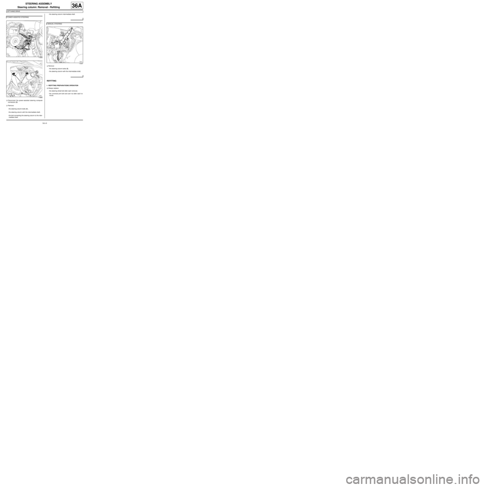
aDisconnect the power-assisted steering computer
connectors (3) .
aRemove:
-the steering column bolts (4) ,
-the steering column with the intermediate shaft,
-the bolt connecting the steering column to the inter-
mediate shaft,-the steering column intermediate shaft.
aRemove:
-the steering column bolts (5) ,
-the steering column with the intermediate shaft,
REFITTING
I - REFITTING PREPARATIONS OPERATION
aAlways replace:
-the steering wheel bolt after each removal,
-the universal joint bolt and cam nut after each re-
moval. POWER ASSISTED STEERING
119858
119883
MANUAL STEERING
119647
Page 162 of 281
36A-11
STEERING ASSEMBLY
Steering column: Removal - Refitting
RIGHT-HAND DRIVE
36A
REMOVAL
I - REMOVAL PREPARATION OPERATION
aUnlock the steering column.
a
Lock the airbag computer using the Diagnostic tool
(see Fault finding - Replacement of components)
(MR 413, 88C, Airbags and seat belt pretensioners).
aDisconnect the battery (see Battery: Removal - Re-
fitting) (MR 411, 80A, Battery).
aRemove:
-the driver's front airbag (see Driver's frontal air-
bag: Removal - Refitting) (MR 411, 88C, Airbags
and pretensioners),
-the steering wheel (see 36A, Steering assembly,
Steering wheel: Removal - Refitting, page 36A-
23) .aRemove the rev counter (see Rev counter: Remov-
al - Refitting) (MR 411, 83A, Instrument panel).
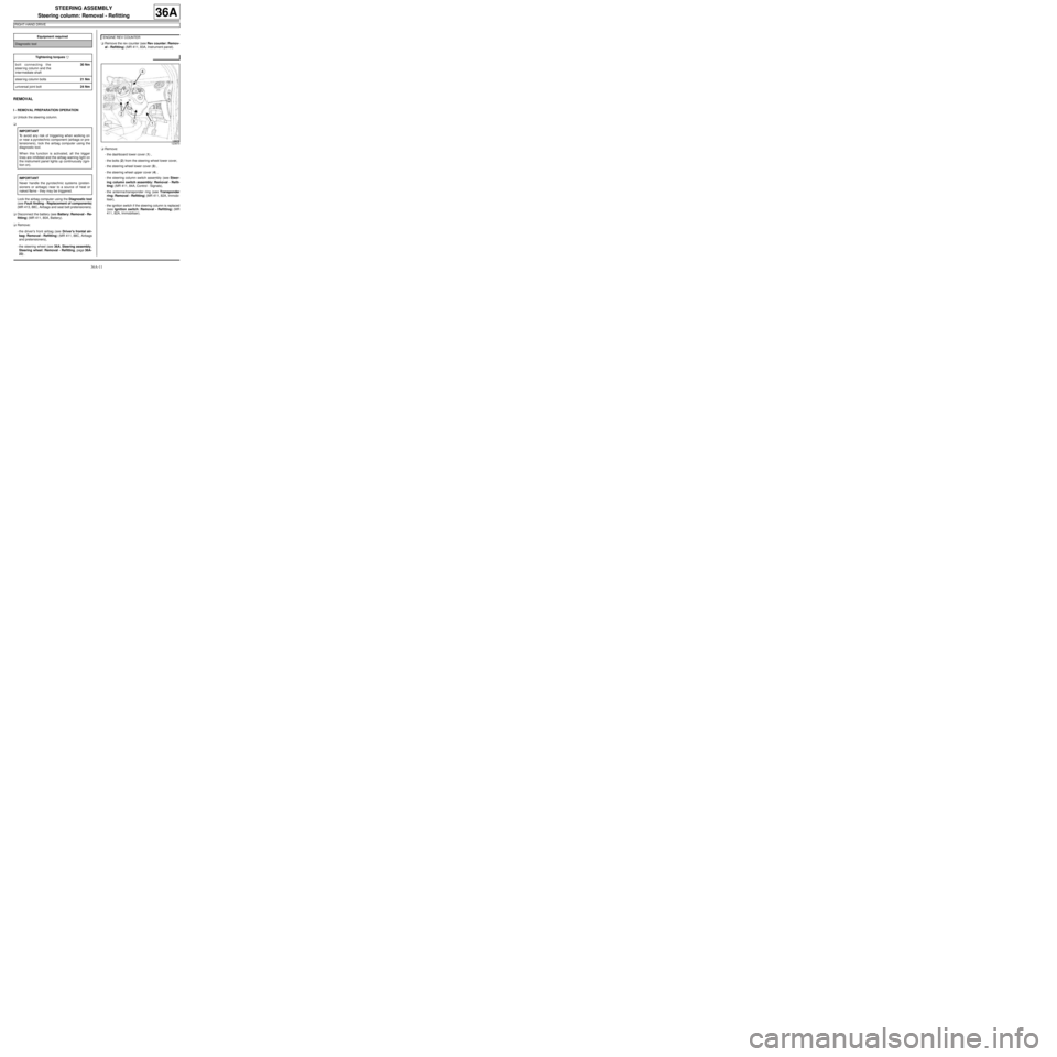
aRemove:
-the dashboard lower cover (1) ,
-the bolts (2) from the steering wheel lower cover,
-the steering wheel lower cover (3) ,
-the steering wheel upper cover (4) ,
-the steering column switch assembly (see Steer-
ing column switch assembly: Removal - Refit-
ting) (MR 411, 84A, Control - Signals),
-the antenna/transponder ring (see Transponder
ring: Removal - Refitting) (MR 411, 82A, Immobi-
liser),
-the ignition switch if the steering column is replaced
(see Ignition switch: Removal - Refitting) (MR
411, 82A, Immobiliser). Equipment required
Diagnostic tool
Tightening torquesm
bolt connecting the
steer ing column and the
inter mediate shaft30 Nm
steer ing column bolts21 Nm
universal joint bolt24 Nm
IMPORTANT
To avoid any risk of triggering when working on
or near a pyrotechnic component (airbags or pre-
tensioners), lock the airbag computer using the
diagnostic tool.
When this function is activated, all the trigger
lines are inhibited and the airbag warning light on
the instrument panel lights up continuously (igni-
tion on).
IMPORTANT
Never handle the pyrotechnic systems (preten-
sioners or airbags) near to a source of heat or
naked flame - they may be triggered.
ENGINE REV COUNTER
123870
Page 163 of 281
36A-12
STEERING ASSEMBLY
Steering column: Removal - Refitting
RIGHT-HAND DRIVE
36A
II - OPERATION FOR REMOVAL OF PART
CONCERNED
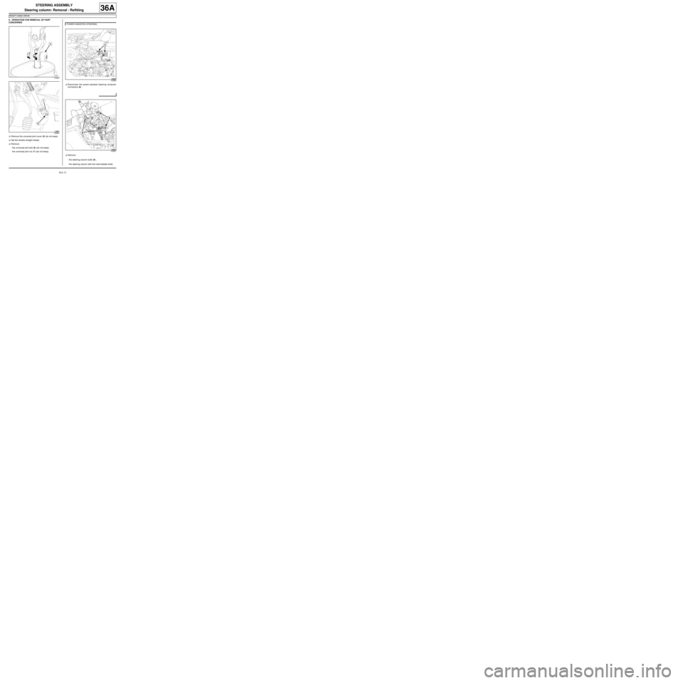
aRemove the universal joint cover (5) (do not keep).
aSet the wheels straight ahead.
aRemove:
-the universal joint bolt (6) (do not keep),
-the universal joint nut (7) (do not keep).aDisconnect the power-assisted steering computer
connectors (8) .
aRemove:
-the steering column bolts (9) ,
-the steering column with the intermediate shaft,
116021
123861
POWER ASSISTED STEERING
123858
123857
Page 164 of 281
36A-13
STEERING ASSEMBLY
Steering column: Removal - Refitting
RIGHT-HAND DRIVE
36A
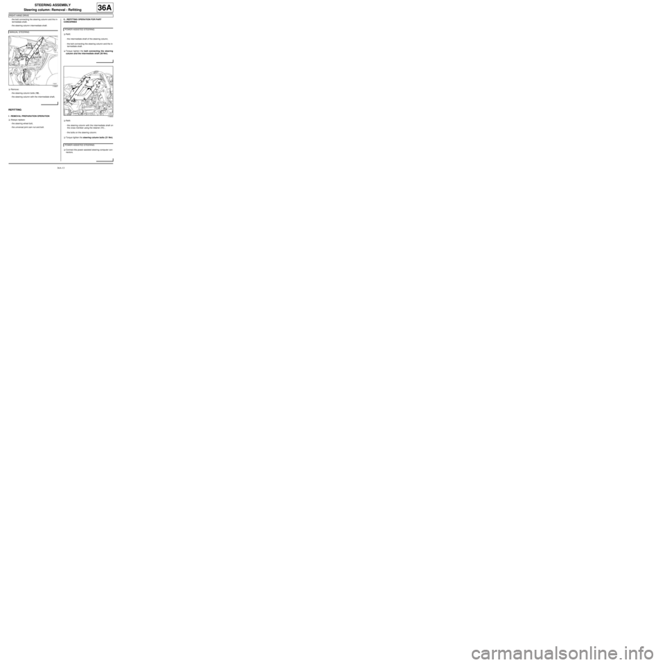
-the bolt connecting the steering column and the in-
termediate shaft,
-the steering column intermediate shaft.
aRemove:
-the steering column bolts (10) ,
-the steering column with the intermediate shaft,
REFITTING
I - REMOVAL PREPARATION OPERATION
aAlways replace:
-the steering wheel bolt,
-the universal joint cam nut and bolt.II - REFITTING OPERATION FOR PART
CONCERNED
aRefit:
-the intermediate shaft of the steering column,
-the bolt connecting the steering column and the in-
termediate shaft.
aTorque tighten the bolt connecting the steering
column and the intermediate shaft (30 Nm).
aRefit:
-the steering column with the intermediate shaft on
the cross member using the retainer (11) ,
-the bolts on the steering column.
aTorque tighten the steering column bolts (21 Nm).
aConnect the power-assisted steering computer con-
nectors. MANUAL STEERING
119647
POWER ASSISTED STEERING
119859
POWER ASSISTED STEERING
Page 166 of 281
36A-15
STEERING ASSEMBLY
Steering column: Removal - Refitting
RIGHT-HAND DRIVE
36A
-the steering wheel lower cover,
-the steering wheel lower cover bolts,
-the dashboard lower cover.
aRefit the rev counter (see Rev counter: Removal -
Refitting) (MR 411, 83A, Instrument panel).
aRefit:
-the steering wheel (see 36A, Steering assembly,
Steering wheel: Removal - Refitting, page 36A-
23) ,
-the driver's front airbag (see Driver's frontal air-
bag: Removal - Refitting) (MR 411, 88C, Airbags
and pretensioners).
aConnect the battery (see Battery: Removal - Refit-
ting) (MR 411, 80A, Battery).
a
Unlock the airbag computer using the Diagnostic
tool (see Fault finding - Replacement of compo-
nents) (MR 413, 88C, Airbags and pretensioners). ENGINE REV COUNTER
IMPORTANT
To avoid a fault with or even triggering of pyro-
technic components (airbags or pretensioners),
check the airbag computer using the diagnostic
tool.