technical specifications Seat Alhambra 2015 User Guide
[x] Cancel search | Manufacturer: SEAT, Model Year: 2015, Model line: Alhambra, Model: Seat Alhambra 2015Pages: 305, PDF Size: 5.46 MB
Page 25 of 305
Airbag system
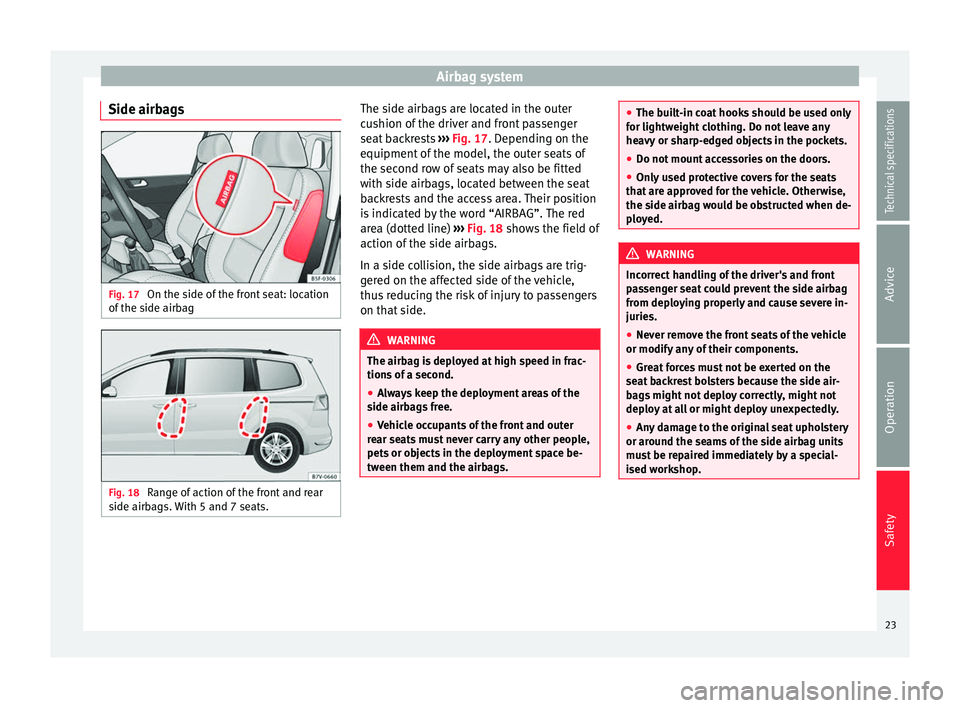
Side airbags Fig. 17
On the side of the front seat: location
of the side airbag Fig. 18
Range of action of the front and rear
side airbags. With 5 and 7 seats. The side airbags are located in the outer
cushion of the driver and front passenger
seat backrests
››› Fig. 17 . Depending on the
equipment of
the model, the outer seats of
the second row of seats may also be fitted
with side airbags, located between the seat
backrests and the access area. Their position
is indicated by the word “AIRBAG”. The red
area (dotted line) ››› Fig. 18
shows the field of
action of the side airbags.
In a side collision, the side airbags are trig-
gered on the affected side of the vehicle,
thus reducing the risk of injury to passengers
on that side. WARNING
The airbag is deployed at high speed in frac-
tions of a second.
● Always keep the deployment areas of the
side airbags free.
● Vehicle occupants of the front and outer
rear seats must never carry any other people,
pets or objects in the deployment space be-
tween them and the airbags. ●
The built-in coat hooks should be used only
for lightweight clothing. Do not leave any
heavy or sharp-edged objects in the pockets.
● Do not mount accessories on the doors.
● Only used protective covers for the seats
that are approved for the vehicle. Otherwise,
the side airbag would be obstructed when de-
ployed. WARNING
Incorrect handling of the driver's and front
passenger seat could prevent the side airbag
from deploying properly and cause severe in-
juries.
● Never remove the front seats of the vehicle
or modify any of their components.
● Great forces must not be exerted on the
seat backrest bolsters because the side air-
bags might not deploy correctly, might not
deploy at all or might deploy unexpectedly.
● Any damage to the original seat upholstery
or around the seams of the side airbag units
must be repaired immediately by a special-
ised workshop. 23
Technical specifications
Advice
Operation
Safety
Page 27 of 305
Airbag system
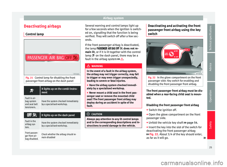
Deactivating airbags Control lamp Fig. 21
Control lamp for disabling the front
passenger front airbag on the dash panel It lights up on the combi-instru-
ment
Fault in air-
bag system
and seat belt
tensioners.Have the system checked immediately
by a specialised workshop.
It lights up on the dash panel
Fault in the
airbag sys-
tem.Have the system checked immediately
by a specialised workshop.
Front passen-
ger front air-
bag disabled.Check whether the airbag should re-
main disabled Several warning and control lamps light up
for a few seconds when the ignition is switch-
ed on, signalling that the function is being
verified. They will switch off after a few sec-
onds.
If the front passenger airbag is deactivated,
the lamp
does not re-
main lit, or if it is lit together with the control
lamp on the dash panel, there may be a
f
ault in the airbag system ››› .
WARNING
In the event of a fault in the airbag system,
the airbag may not trigger correctly, may fail
to trigger or may even trigger unexpectedly,
leading to severe or fatal injuries.
● Have the airbag system checked immedi-
ately by a specialised workshop.
● Never mount a child seat in the front pas-
senger seat or remove the mounted child
seat! The front passenger front airbag may
deploy during an accident in spite of the
fault. CAUTION
Always pay attention to any lit control lamps
and to the corresponding descriptions and in-
structions to avoid damage to the vehicle. Deactivating and activating the front
passenger front airbag using the key
switch
Fig. 22
In the glove compartment on the front
passenger side: Key switch for enabling and
disabling the front passenger front airbag. The front passenger front airbag must be dis-
abled when a rear-facing child seat is moun-
ted.
Disabling the front passenger front airbag
● Switch the ignition off.
● Open the glove compartment on the front
passenger side.
● Unfold the vehicle key shaft ››› page 54.
● Insert the key into the slot of the switch for
deactivating the front passenger airbag
››› Fig. 22 . About 3/4 of the key should enter,
a s
far as it will go. »
25
Technical specifications
Advice
Operation
Safety
Page 29 of 305
Transporting children safely
WARNING
Make sure children are properly belted in and
correctly secured to avoid severe or fatal inju-
ries while the vehicle is in motion.
● Never use a rear-facing child seat in the
front passenger seat if the front passenger
front airbag is enabled.
● Children up to 12 years old should always
travel on the rear seat.
● Children must always be protected with an
approved child restraint system suited to
their height and weight.
● Children must assume the proper sitting
position and be properly belted in while trav-
elling.
● Ensure the seat backrest is upright when a
child seat is being used on it.
● Do not allow the child's head or other part
of his or her body to fall into the deployment
area of the side airbags.
● Make sure the belt webbing is correctly
positioned.
● Never hold children or babies on your lap or
in your arms.
● Only one child may occupy a child seat.
● If you are using a child seat with a base or
foot, always install this base or foot correctly
and safely.
● If the vehicle has a storage compartment in
the footwell in front of the last row of seats,
this compartment cannot be used as de-
signed; on the contrary: It must be filled us- ing the specially designed accessory so that
the base or foot is correctly supported by the
closed compartment and the child seat is se-
cured properly. If this compartment is not
suitably secured when using a child seat with
a base or foot then the compartment cover
could rupture in an accident and the child will
be ejected and suffer serious injury.
●
Please read and observe the child seat
manufacturer's handling instructions. WARNING
An empty or loose child seat could fly uncon-
trollably around the vehicle interior and
cause injuries in the event of an accident or
sudden braking.
● When not in use while the vehicle is in mo-
tion, always safely secure the child seat or
store it in the luggage compartment. Note
Replace the child seat after an accident, as it
may have invisible damage. Important information regarding the
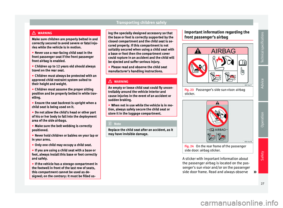
front passenger's airbag
Fig. 23
Passenger's side sun visor: airbag
sticker. Fig. 24
On the rear frame of the passenger
side door: airbag sticker. A sticker with important information about
the passenger airbag is located on the pas-
senger's sun visor and/or on the passenger
side door frame. Read and always observe
»
27Technical specifications
Advice
Operation
Safety
Page 31 of 305
Transporting children safely
the most protection possible for babies and
small children in most accidents. Note
Other accessories may be required to fit the
child retention system with a base or foot se- curity and safely. Contact a technical service
centre or specialised workshop.
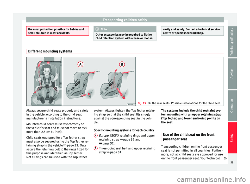
Different mounting systems
Fig. 25
On the rear seats: Possible installations for the child seat. Always secure child seats properly and safely
in the vehicle according to the child seat
manufacturer's installation instructions.
Mounted child seats must rest correctly on
the vehicle's seat and must not move or rock
more than 2.5 cm (1 inch).
Child seats equipped for a Top Tether strap
must also be secured using the Top Tether re-
taining strap in the vehicle
››› page 32. Only
secure the retaining belt to the rings fitted for
this purpose and identified as Top Tether.
Not all rings can be used with the Top Tether system. Always tighten the Top Tether retain-
ing strap so that the child seat fits snugly
against the corresponding seat in the vehi-
cle.
Specific mounting systems for each country
Europe : ISOFIX retaining rings and upper
r et
aining strap ››› page 32 and
››› page 32.
Three-point
seat belt and upper retaining
strap ››› page 31
.
A B The systems include the child restraint sys-
tem mounting with an upper retaining strap
(Top Tether) and lower anchoring points on
the seat.
Use of the child seat on the front
passenger seat Transporting children on the front passenger
seat is not permitted in all countries. Further-
more, not all child seats are approved for use
on the front passenger seat. Your technical
»
29
Technical specifications
Advice
Operation
Safety
Page 33 of 305
Transporting children safely
seat so that the child has enough space.
Therefore, adapt the front passenger seat to
the size of the child seat and the height of
the child. Ensure the passenger is in the cor-
rect position
›
›› page 6.
Move the second and third rows of seats fully
back and lock them. Place the seat backs in a
vertical position and fold the head restraints
down.
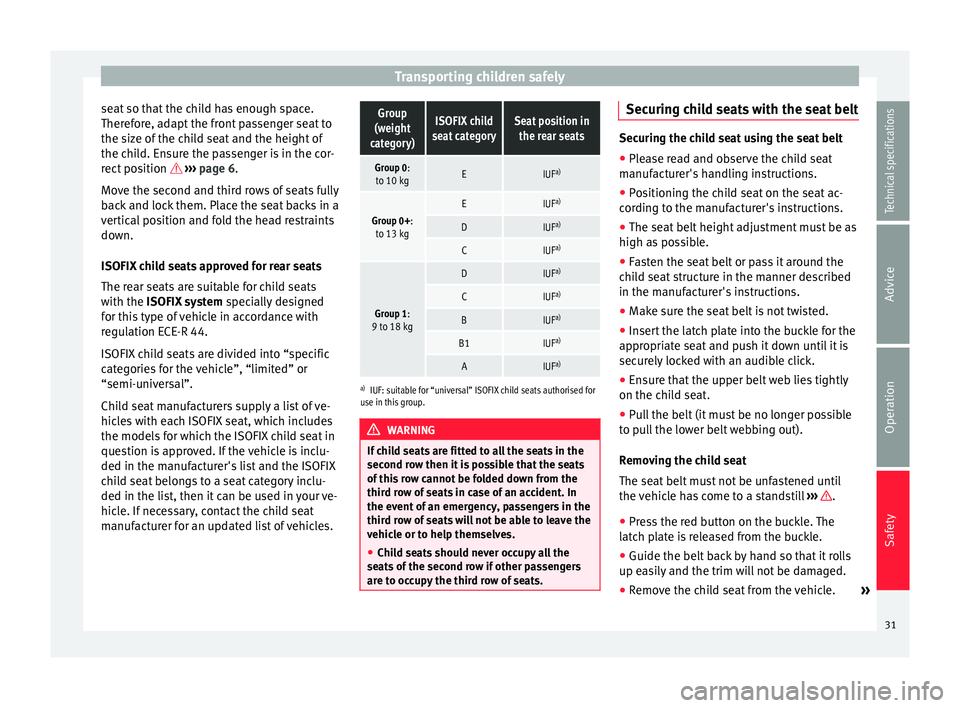
ISOFIX child seats approved for rear seats
The rear seats are suitable for child seats
with the ISOFIX system spec
ially designed
for this type of vehicle in accordance with
regulation ECE-R 44.
ISOFIX child seats are divided into “specific
categories for the vehicle”, “limited” or
“semi-universal”.
Child seat manufacturers supply a list of ve-
hicles with each ISOFIX seat, which includes
the models for which the ISOFIX child seat in
question is approved. If the vehicle is inclu-
ded in the manufacturer's list and the ISOFIX
child seat belongs to a seat category inclu-
ded in the list, then it can be used in your ve-
hicle. If necessary, contact the child seat
manufacturer for an updated list of vehicles.
Group
(weight
category)ISOFIX child
seat categorySeat position in the rear seats
Group 0:to 10 kgEIUF a)
Group 0+:
to 13 kgEIUF a)
DIUFa)
CIUFa)
Group 1:
9 to 18 kg
DIUF a)
CIUFa)
BIUFa)
B1IUFa)
AIUFa)
a)
IUF: suitable for “universal” ISOFIX child seats authorised for
use in this group. WARNING
If child seats are fitted to all the seats in the
second row then it is possible that the seats
of this row cannot be folded down from the
third row of seats in case of an accident. In
the event of an emergency, passengers in the
third row of seats will not be able to leave the
vehicle or to help themselves.
● Child seats should never occupy all the
seats of the second row if other passengers
are to occupy the third row of seats. Securing child seats with the seat belt
Securing the child seat using the seat belt
● Please read and observe the child seat
manufacturer's handling instructions.
● Positioning the child seat on the seat ac-
cording to the manufacturer's instructions.
● The seat belt height adjustment must be as
high as possible.
● Fasten the seat belt or pass it around the
child seat structure in the manner described
in the manufacturer's instructions.
● Make sure the seat belt is not twisted.
● Insert the latch plate into the buckle for the
appropriate seat and push it down until it is
securely locked with an audible click.
● Ensure that the upper belt web lies tightly
on the child seat.
● Pull the belt (it must be no longer possible
to pull the lower belt webbing out).
Removing the child seat
The seat belt must not be unfastened until
the vehicle has come to a standstill ››› .
● Press the red button on the buckle. The
latch plate is released from the buckle.
● Guide the belt back by hand so that it rolls
up easily and the trim will not be damaged.
● Remove the child seat from the vehicle. »
31
Technical specifications
Advice
Operation
Safety
Page 35 of 305
Transporting children safely
● Push the head restraint down as far as it
will go. Ensure that it does not interfere with
the seatbelt from the upper attachment.
● Tighten the strap so that the top of the
child seat rests on the seat backrest. WARNING
Child seats with lower anchor points and with
an upper retaining strap must be installed in
line with the manufacturer's instructions.
Failure to comply could result in severe inju-
ries.
● Always secure just one retaining strap from
a c hi
ld seat to a retaining ring (for Top Tether)
on the seat backrest on the rear seat in the
boot.
● Never secure a child seat to the retaining
rings.
● Never secure a child seat to the movable at-
tachment elements for vehicles with an at-
tachment element and rail system .Integrated child seat
Introduction The integrated child seat is only suitable for
children in Group 2 (15-25 kg) and Group 3
(22-36 kg), according to the ECE-R 44 regula-
tion. WARNING
Child travelling without their seat belt fas-
tened or not secured using a suitable re-
straint system may sustain fatal injuries if
the airbag is deployed.
● Children up to 12 years old should always
travel on the rear seat.
● Always disable the front passenger front
airbag if, in exceptional cases, you have no
alternative but to transport a child in a rear-
facing child safety seat on the front passen-
ger seat.
● Children must always be protected with a
child restraint system suited to their height
and weight.
● Always fasten children's seat belts correct-
ly. WARNING
Children must travel in a child seat appropri-
ate to their weight and height while the vehi-
cle is in motion.
● Children must always be protected with a
child restraint system suited to their height
and weight.
● Children must assume the proper sitting
position and be properly belted in while trav-
elling.
● The shoulder part of the seat belt must lie
approximately on the centre of the shoulder,
never across the neck or the arm. ●
The seat belt must lie close to the upper
part of the body.
● The lap belt part must lie across the pelvis,
not across the stomach, and always fit close-
ly.
● Allow the belt to retract until it fits tightly
over the child's seat.
● Never hold children or babies on your lap.
● Always use a child seat and the seat belt
for children who are under 1.5 m tall. The nor-
mal seat belt could cause injuries to the ab-
domin a
l and neck areas.
● Only one child may occupy a child seat.
● Read and follow the information and warn-
ings provided by the child seat manufacturer.
● Never leave an unsupervised child alone on
a child seat or in the vehicle.
● All modifications to the integrated child
seat must be carried out by a specialised
workshop.
● Replace the child seat or any seat compo-
nents damaged or involved in an accident. WARNING
Loose objects could fly uncontrollably around
the vehicle interior and cause injuries in the
event of an accident or sudden braking.
● Do not leave toys or other hard, loose ob-
jects on the child seat or on the seat while
the vehicle is in motion. 33
Technical specifications
Advice
Operation
Safety
Page 37 of 305
Transporting children safely
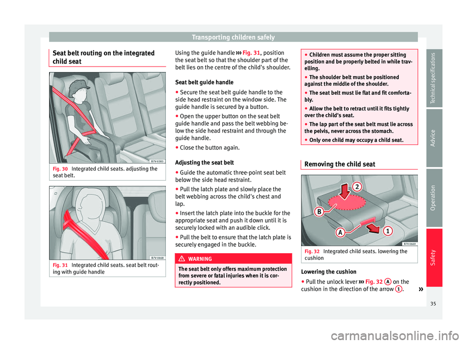
Seat belt routing on the integrated
child seat Fig. 30
Integrated child seats. adjusting the
seat belt. Fig. 31
Integrated child seats. seat belt rout-
ing with guide handle Using the guide handle
››› Fig. 31 , position
the se at
belt so that the shoulder part of the
belt lies on the centre of the child's shoulder.
Seat belt guide handle
● Secure the seat belt guide handle to the
side head restraint on the window side. The
guide handle is secured by a button.
● Open the upper button on the seat belt
guide handle and pass the belt webbing be-
low the side head restraint and through the
guide handle.
● Close the button again.
Adjusting the seat belt
● Guide the automatic three-point seat belt
below the side head restraint.
● Pull the latch plate and slowly place the
belt webbing across the child's chest and
lap.
● Insert the latch plate into the buckle for the
appropriate seat and push it down until it is
securely locked with an audible click.
● Pull the belt to ensure that the latch plate is
securely engaged in the buckle. WARNING
The seat belt only offers maximum protection
from severe or fatal injuries when it is cor-
rectly positioned. ●
Children must assume the proper sitting
position and be properly belted in while trav-
elling.
● The shoulder belt must be positioned
against the middle of the shoulder.
● The seat belt must lie flat and fit comforta-
bly.
● Allow the belt to retract until it fits tightly
over the child's seat.
● The lap part of the seat belt must lie across
the pelvis, never across the stomach.
● Only one child may occupy a child seat. Removing the child seat
Fig. 32
Integrated child seats. lowering the
cushion Lowering the cushion
● Pull the unlock lever ››› Fig. 32 A on the
cushion in the direction of the arrow 1 .
»
35
Technical specifications
Advice
Operation
Safety
Page 41 of 305
Cockpit
Operation
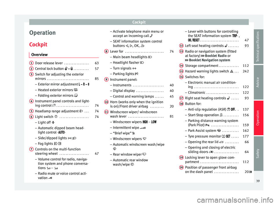
Cockpit Overview Door release lever
. . . . . . . . . . . . . . . . 63
Central lock button . . . . . . . . . . 57
Switch for adjusting the exterior
mirrors . . . . . . . . . . . . . . . . . . . . . . . . . . . 85
– Exterior mirror adjustment
– Heated exterior mirrors
– Folding exterior mirrors
Instrument panel controls and light-
ing control . . . . . . . . . . . . . . . . . . . . . 74
Headlamp range adjustment . . . 74
Light switch . . . . . . . . . . . . . . . . . . . 74
– Light off - -
– Automatic dipped beam head-
light control - -
– Side/dipped lights
– Fog lights
Controls on the multi-function
steering wheel . . . . . . . . . . . . . . . . . . . 47
– Volume control for radio, naviga-
tion system and phone conversa-
tions –
– Radio mute or voice control acti-
vation
1 2
3
4
5
6
7 –
Activate telephone main menu or
accept an incoming call
– SEAT information system control
buttons ,
, OK,
Lever for . . . . . . . . . . . . . . . . . . . . . . . . . 74
– Main beam headlights
– Headlight flasher
– Turn signals
– Parking lights
Instrument panel: – Instruments . . . . . . . . . . . . . . . . . . . . 40
– Digital display . . . . . . . . . . . . . . . . . . 40
– Control and warning lamps . . . . . .45
Horn (works only when the ignition
is on)/Front driver airbag . . . . . . . . .20
Windscreen wiper/ windscreen
wash lever . . . . . . . . . . . . . . . . . . . . . . . 81
– Windscreen wipers –
– Intermittent wipe
– “Brief wipe” x
– Windscreen wipers
– Automatic windscreen wash/wipe
– Rear window wiper
– Automatic rear window
wash/wipe
8
9
10
11 –
Lever with buttons for controlling
the SEAT information system - ,
/
. . . . . . . . . . . . . . . . . . . . . . . . . 47
L ef
t seat heating controls . . . . . . . 93
Radio or navigation system (fitted
at factory) ››› Booklet Radio or
››› Booklet Navigation system
Storage compartment . . . . . . . . . . . . .112
Hazard warning lights switch . . . 242
Switches for: – Electronic manual air condition-
ing . . . . . . . . . . . . . . . . . . . . . . . . . . . . . 122
– Climatronic . . . . . . . . . . . . . . . . . . . . . 122
Right seat heating controls . . . . . 93
Button for: – Anti-slip regulation (ASR) . .137
– Start-Stop operation . . . . . . . . . .156
– Parking distance warning system
(Park Pilot) . . . . . . . . . . . . . . . . . . 159
– Park Assist system . . . . . . . . . . . 162
– Tyre pressure monitor . . . . .177
– Opening the rear lid . . . . . . . . .66
– Opening and closing of electric
sliding doors . . . . . . . . . . . . . . . . 64
Locking lever to open glove com-
partment . . . . . . . . . . . . . . . . . . . . . . . . . 112
Position of passenger front airbag
on the dash panel . . . . . . . . . . . . . . . . 20
»
12 13
14
15
16
17
18
19
20
39
Technical specifications
Advice
Operation
Safety
Page 43 of 305
Cockpit
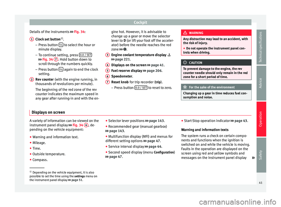
Details of the instruments ››› Fig. 34 :
C loc
k set button 1)
.
– Press button to select the hour or
minute display.
– To continue setting, press 0.0 / SET›››
Fig. 34 7 . Hold button down to
scroll through the numbers quickly.
– Press button again to end the clock
setting.
Rev counter (with the engine running, in
thousands of revolutions per minute).
The beginning of the red zone of the rev
counter indicates the maximum speed in
any gear after running-in and with the en-
1 2 gine hot. However, it is advisable to
change up a gear or move the selector
lever to
D
(or lift your foot off the acceler-
at
or) before the needle reaches the red
zone ››› .
Engine coolant temperature display
››› page 221 .
Di s
plays on the screen ››› page 41.
Fuel reserve display ››› page 206.
Speedometer.
Reset knob for trip recorder (trip).
– Pre
ss button 0.0 / SET to reset to zero.
3 4
5
6
7 WARNING
Any distraction may lead to an accident, with
the risk of injury.
● Do not operate the instrument panel con-
trols when driving. CAUTION
To prevent damage to the engine, the rev
counter needle should only remain in the red
zone for a short period of time. For the sake of the environment
Changing up a gear in time reduces fuel con-
sumption and noise. Displays on screen
A variety of information can be viewed on the
instrument panel display
››› Fig. 34 4 , de-
pending on the vehicle equipment:
● Warning and information text.
● Mileage.
● Time.
● Outside temperature.
● Compass. ●
Selector lever positions ››› page 143.
● Recommended gear (manual gearbox)
››› page 143 .
● Mu
ltifunction display (MFI) and menus for
different setting options ››› page 47.
● Service interval display ››› page 44 .
● Second speed display (menu Configuration)
››› page 47. ●
Star
t-Stop operation indicator
››› page 43.
Warning and information texts
The system runs a check on certain compo-
nents and functions when the ignition is
switched on and while the vehicle is moving.
Faults in the operation are displayed on the
screen using red and yellow symbols and
messages on the instrument panel display »1)
Depending on the vehicle equipment, it is also
possible to set the time using the settings menu on
the in s
trument panel display ››› page 51.
41
Technical specifications
Advice
Operation
Safety
Page 45 of 305
Cockpit
● Press button three times. The odometer
display flashes on the instrument panel dis-
play.
● Press button 0.0 / SET once. “mph”
or “km/h” is displayed briefly instead of the
odometer.
● This activates the second speed display. To
switch it off, repeat the procedure.
This option cannot be deactivated in models
destined for countries in which the second
speed must always be visible.
Start-Stop operating display.
Updated information relating to the status is
displayed on the instrument panel
››› page 156 . WARNING
Observe the safety warnings ››› in Control
and warning lamps on page 47. WARNING
Even though outside temperatures are above
freezing, some roads and bridges may be icy.
● At outside temperatures above +4°C
(+39°F), even when the “ice crystal symbol”
is not visible, there may still be patches of ice
on the road.
● Never rely on the outside temperature indi-
cator! Note
● Different versions of the instrument panel
are available and therefore the versions and
instructions on the display may vary. In the
case of displays without warning or informa-
tion texts, faults are indicated exclusively by
the warning lamps.
● When several warnings are active at the
same time, the symbols are shown succes-
sively for a few seconds and will stay on until
the fault is rectified. Compass*
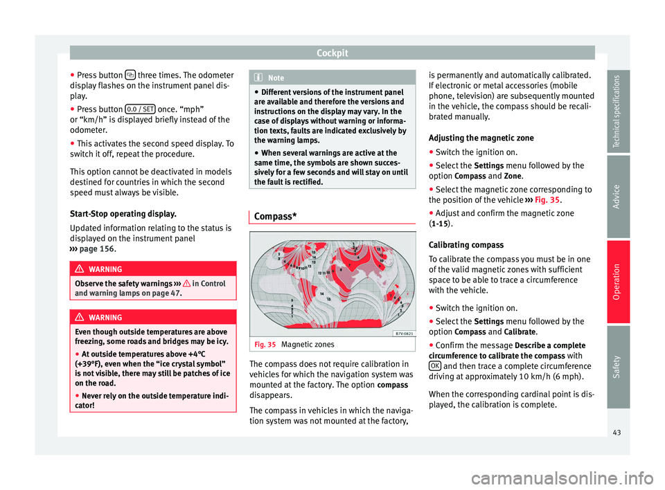
Fig. 35
Magnetic zones The compass does not require calibration in
vehicles for which the navigation system was
mounted at the factory. The option
compass
disappears.
The compass in vehicles in which the naviga-
tion system was not mounted at the factory, is permanently and automatically calibrated.
If electronic or metal accessories (mobile
phone, television) are subsequently mounted
in the vehicle, the compass should be recali-
brated manually.
Adjusting the magnetic zone
● Switch the ignition on.
● Select the Settings menu followed by the
option Compass and Zone.
● Sel ect
the magnetic zone corresponding to
the position of the vehicle ››› Fig. 35.
● Adjus
t and confirm the magnetic zone
(1-15).
Calibrating compass
To calibrate the compass you must be in one
of the valid magnetic zones with sufficient
space to be able to trace a circumference
with the vehicle.
● Switch the ignition on.
● Select the Settings menu followed by the
option Compass and Calibrate.
● Confirm the message Describe a complete
circumference to calibrate the compass with OK and then trace a complete circumference
driving at approximately 10 km/h (6 mph).
When the corresponding cardinal point is dis-
played, the calibration is complete.
43
Technical specifications
Advice
Operation
Safety