ECO mode Seat Alhambra 2015 Owner's Manual
[x] Cancel search | Manufacturer: SEAT, Model Year: 2015, Model line: Alhambra, Model: Seat Alhambra 2015Pages: 305, PDF Size: 5.46 MB
Page 12 of 305
Safety
CAUTION
The pedals must always have free and unob-
structed passage to the floor. For example, in
case of a fault in the brake circuit, the brake
pedal will need to be pressed further to stop
the vehicle. To press the brake pedal down
further will require more force than usual. Seat belts
The whys and wherefores of
seat belts Introduction Check the condition of all the seat belts at
regular intervals. If you notice that the belt
webbing, fittings, retractor mechanism or
buckle of any of the belts is damaged, the
belt must be replaced immediately by a spe-
cialised workshop
››› . The specialised
workshop must use the appropriate spare
parts corresponding to the vehicle, the
equipment and the model year. SEAT recom-
mends taking your car in for technical serv-
ice. WARNING
Unbuckled or badly buckled seat belts in-
crease the risk of severe or even fatal inju-
ries. The seat belt cannot offer its full protec-
tion if it is not fastened and used correctly.
● Seat belts are the most effective way of re-
ducing the risk of sustaining severe or fatal
injuries in the event of an accident. Seat belts
must be correctly fastened when the vehicle
is in motion to protect the driver and all vehi-
cle occupants.
● Before each trip, every occupant in the ve-
hicle occupants must sit properly, correctly fasten the seat belt belonging to his or her
seat and keep it fastened throughout the trip.
This also applies to other vehicle occupants
when driving in town.
●
When travelling, children must be secured
in the vehicle with a child restraint system
suitable for their weight and height and with
the seat belts correctly fastened
››› page 26.
● Ins
truct your passengers to fasten their
seat belts properly before driving off.
● Insert the latch plate into the buckle for the
appropriate seat and ensure it is engaged.
Using the latch plate in the buckle of another
seat will not protect you properly and may
cause severe injuries.
● Do not allow liquids or foreign bodies to en-
ter the buckle fastenings. This could damage
the buckles and seat belts.
● Never unbuckle your seat belt when the ve-
hicle is moving.
● Never allow more than one passenger to
share the same seat belt.
● Never hold children or babies on your lap
sharing the same seat belt.
● Loose, bulky clothing (such as a jacket) im-
pairs the proper fit and function of the seat
belt. 10
Page 25 of 305
Airbag system
Side airbags Fig. 17
On the side of the front seat: location
of the side airbag Fig. 18
Range of action of the front and rear
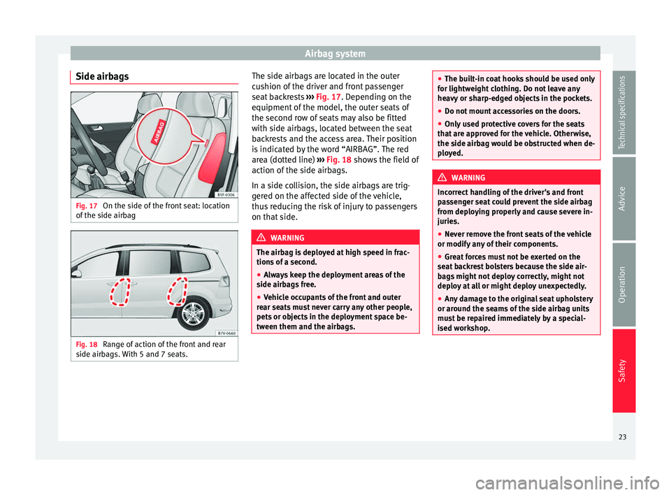
side airbags. With 5 and 7 seats. The side airbags are located in the outer
cushion of the driver and front passenger
seat backrests
››› Fig. 17 . Depending on the
equipment of
the model, the outer seats of
the second row of seats may also be fitted
with side airbags, located between the seat
backrests and the access area. Their position
is indicated by the word “AIRBAG”. The red
area (dotted line) ››› Fig. 18
shows the field of
action of the side airbags.
In a side collision, the side airbags are trig-
gered on the affected side of the vehicle,
thus reducing the risk of injury to passengers
on that side. WARNING
The airbag is deployed at high speed in frac-
tions of a second.
● Always keep the deployment areas of the
side airbags free.
● Vehicle occupants of the front and outer
rear seats must never carry any other people,
pets or objects in the deployment space be-
tween them and the airbags. ●
The built-in coat hooks should be used only
for lightweight clothing. Do not leave any
heavy or sharp-edged objects in the pockets.
● Do not mount accessories on the doors.
● Only used protective covers for the seats
that are approved for the vehicle. Otherwise,
the side airbag would be obstructed when de-
ployed. WARNING
Incorrect handling of the driver's and front
passenger seat could prevent the side airbag
from deploying properly and cause severe in-
juries.
● Never remove the front seats of the vehicle
or modify any of their components.
● Great forces must not be exerted on the
seat backrest bolsters because the side air-
bags might not deploy correctly, might not
deploy at all or might deploy unexpectedly.
● Any damage to the original seat upholstery
or around the seams of the side airbag units
must be repaired immediately by a special-
ised workshop. 23
Technical specifications
Advice
Operation
Safety
Page 33 of 305
Transporting children safely
seat so that the child has enough space.
Therefore, adapt the front passenger seat to
the size of the child seat and the height of
the child. Ensure the passenger is in the cor-
rect position
›
›› page 6.
Move the second and third rows of seats fully
back and lock them. Place the seat backs in a
vertical position and fold the head restraints
down.
ISOFIX child seats approved for rear seats
The rear seats are suitable for child seats
with the ISOFIX system spec
ially designed
for this type of vehicle in accordance with
regulation ECE-R 44.
ISOFIX child seats are divided into “specific
categories for the vehicle”, “limited” or
“semi-universal”.
Child seat manufacturers supply a list of ve-
hicles with each ISOFIX seat, which includes
the models for which the ISOFIX child seat in
question is approved. If the vehicle is inclu-
ded in the manufacturer's list and the ISOFIX
child seat belongs to a seat category inclu-
ded in the list, then it can be used in your ve-
hicle. If necessary, contact the child seat
manufacturer for an updated list of vehicles.
Group
(weight
category)ISOFIX child
seat categorySeat position in the rear seats
Group 0:to 10 kgEIUF a)
Group 0+:
to 13 kgEIUF a)
DIUFa)
CIUFa)
Group 1:
9 to 18 kg
DIUF a)
CIUFa)
BIUFa)
B1IUFa)
AIUFa)
a)
IUF: suitable for “universal” ISOFIX child seats authorised for
use in this group. WARNING
If child seats are fitted to all the seats in the
second row then it is possible that the seats
of this row cannot be folded down from the
third row of seats in case of an accident. In
the event of an emergency, passengers in the
third row of seats will not be able to leave the
vehicle or to help themselves.
● Child seats should never occupy all the
seats of the second row if other passengers
are to occupy the third row of seats. Securing child seats with the seat belt
Securing the child seat using the seat belt
● Please read and observe the child seat
manufacturer's handling instructions.
● Positioning the child seat on the seat ac-
cording to the manufacturer's instructions.
● The seat belt height adjustment must be as
high as possible.
● Fasten the seat belt or pass it around the
child seat structure in the manner described
in the manufacturer's instructions.
● Make sure the seat belt is not twisted.
● Insert the latch plate into the buckle for the
appropriate seat and push it down until it is
securely locked with an audible click.
● Ensure that the upper belt web lies tightly
on the child seat.
● Pull the belt (it must be no longer possible
to pull the lower belt webbing out).
Removing the child seat
The seat belt must not be unfastened until
the vehicle has come to a standstill ››› .
● Press the red button on the buckle. The
latch plate is released from the buckle.
● Guide the belt back by hand so that it rolls
up easily and the trim will not be damaged.
● Remove the child seat from the vehicle. »
31
Technical specifications
Advice
Operation
Safety
Page 45 of 305
Cockpit
● Press button three times. The odometer
display flashes on the instrument panel dis-
play.
● Press button 0.0 / SET once. “mph”
or “km/h” is displayed briefly instead of the
odometer.
● This activates the second speed display. To
switch it off, repeat the procedure.
This option cannot be deactivated in models
destined for countries in which the second
speed must always be visible.
Start-Stop operating display.
Updated information relating to the status is
displayed on the instrument panel
››› page 156 . WARNING
Observe the safety warnings ››› in Control
and warning lamps on page 47. WARNING
Even though outside temperatures are above
freezing, some roads and bridges may be icy.
● At outside temperatures above +4°C
(+39°F), even when the “ice crystal symbol”
is not visible, there may still be patches of ice
on the road.
● Never rely on the outside temperature indi-
cator! Note
● Different versions of the instrument panel
are available and therefore the versions and
instructions on the display may vary. In the
case of displays without warning or informa-
tion texts, faults are indicated exclusively by
the warning lamps.
● When several warnings are active at the
same time, the symbols are shown succes-
sively for a few seconds and will stay on until
the fault is rectified. Compass*
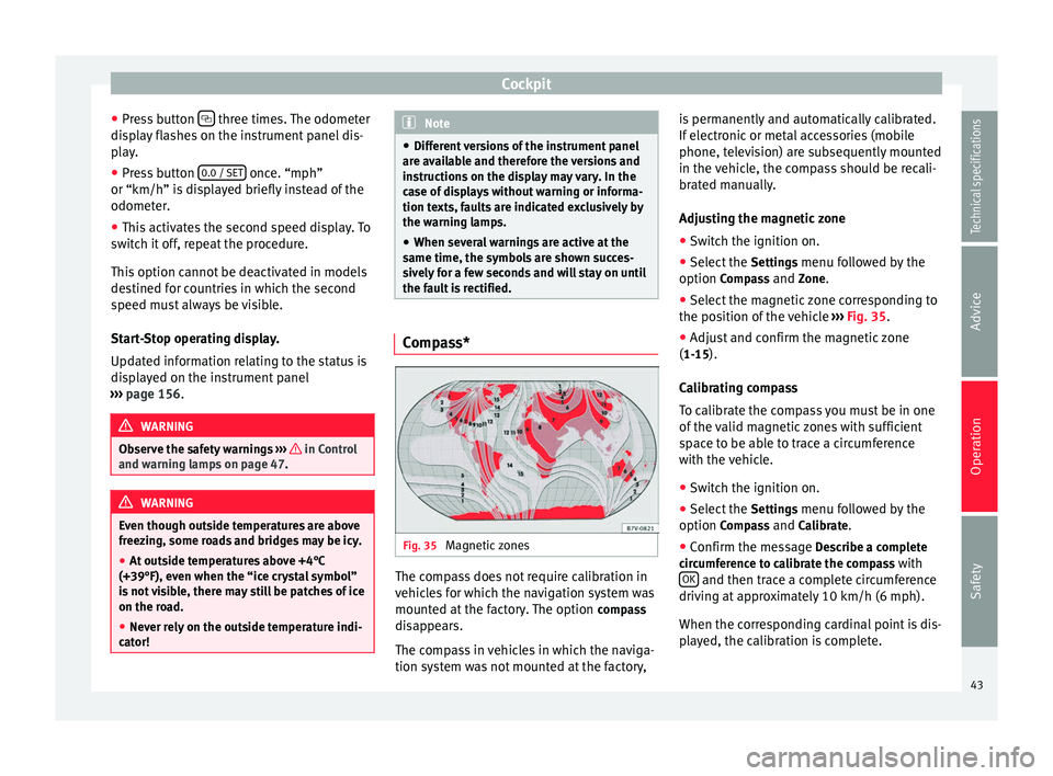
Fig. 35
Magnetic zones The compass does not require calibration in
vehicles for which the navigation system was
mounted at the factory. The option
compass
disappears.
The compass in vehicles in which the naviga-
tion system was not mounted at the factory, is permanently and automatically calibrated.
If electronic or metal accessories (mobile
phone, television) are subsequently mounted
in the vehicle, the compass should be recali-
brated manually.
Adjusting the magnetic zone
● Switch the ignition on.
● Select the Settings menu followed by the
option Compass and Zone.
● Sel ect
the magnetic zone corresponding to
the position of the vehicle ››› Fig. 35.
● Adjus
t and confirm the magnetic zone
(1-15).
Calibrating compass
To calibrate the compass you must be in one
of the valid magnetic zones with sufficient
space to be able to trace a circumference
with the vehicle.
● Switch the ignition on.
● Select the Settings menu followed by the
option Compass and Calibrate.
● Confirm the message Describe a complete
circumference to calibrate the compass with OK and then trace a complete circumference
driving at approximately 10 km/h (6 mph).
When the corresponding cardinal point is dis-
played, the calibration is complete.
43
Technical specifications
Advice
Operation
Safety
Page 46 of 305
Operation
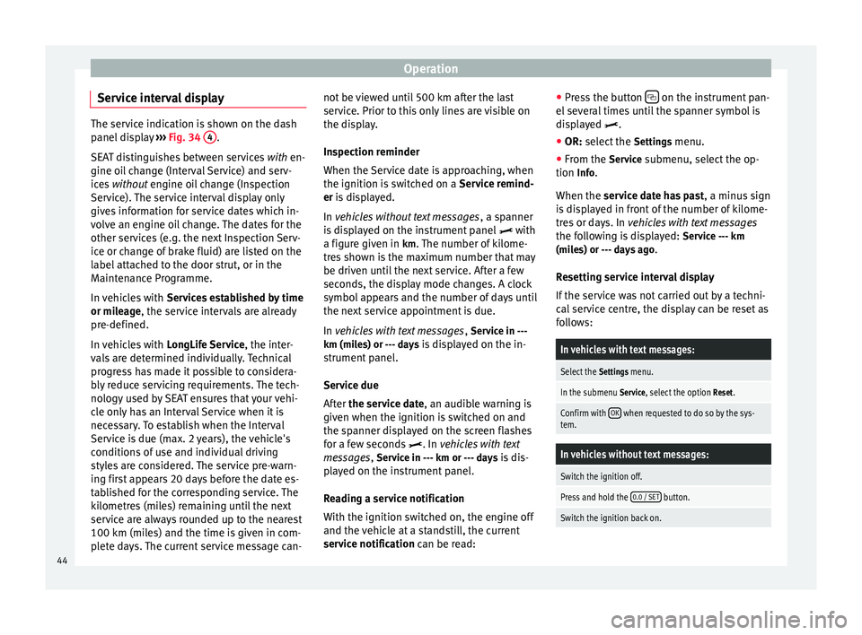
Service interval display The service indication is shown on the dash
panel display
››› Fig. 34 4 .
SEAT distinguishes between services with en-
gine oi l
change (Interval Service) and serv-
ices without
engine oil change (Inspection
Service). The service interval display only
gives information for service dates which in-
volve an engine oil change. The dates for the
other services (e.g. the next Inspection Serv-
ice or change of brake fluid) are listed on the
label attached to the door strut, or in the
Maintenance Programme.
In vehicles with Services established by time
or mileage, the service intervals are already
pr e-defined.
In
vehicles with LongLife Service , the inter-
vals are determined individually. Technical
progress has made it possible to considera-
bly reduce servicing requirements. The tech-
nology used by SEAT ensures that your vehi-
cle only has an Interval Service when it is
necessary. To establish when the Interval
Service is due (max. 2 years), the vehicle's
conditions of use and individual driving
styles are considered. The service pre-warn-
ing first appears 20 days before the date es-
tablished for the corresponding service. The
kilometres (miles) remaining until the next
service are always rounded up to the nearest
100 km (miles) and the time is given in com-
plete days. The current service message can- not be viewed until 500 km after the last
service. Prior to this only lines are visible on
the display.
Inspection reminder
When the Service date is approaching, when
the ignition is switched on a
Service remind-
er
is displayed.
In
vehicles without text messages , a spanner
is displayed on the instrument panel with
a figure given in km. The number of kilome- tre
s shown is the maximum number that may
be driven until the next service. After a few
seconds, the display mode changes. A clock
symbol appears and the number of days until
the next service appointment is due.
In vehicles with text messages , Serv
ice in ---
km (miles) or --- days is displayed on the in- strument panel.
Service due
After the service date, an audible warning is
giv
en when the ignition is switched on and
the spanner displayed on the screen flashes
for a few seconds . In
vehicles with text
messages, Service in --- km or --- days is dis-
played on the instrument panel.
Reading a service notification
With the ignition switched on, the engine off
and the vehicle at a standstill, the current
service notification
can be read: ●
Press the button on the instrument pan-
el several times until the spanner symbol is
displayed
.
● OR:
select the Setting
s menu.
● From the
Service submenu, select the op-
tion Info.
When the service date has past , a minus
sign
is displayed in front of the number of kilome-
tres or days. In vehicles with text messages
the following is displayed: Service --- km
(miles) or --- days ago .
Resetting service interval display
If the service was not carried out by a techni-
cal service centre, the display can be reset as
follows:
In vehicles with text messages:
Select the Settings menu.
In the submenu Service, select the option Reset.
Confirm with OK when requested to do so by the sys-
tem.
In vehicles without text messages:
Switch the ignition off.
Press and hold the 0.0 / SET button.
Switch the ignition back on.44
Page 47 of 305
CockpitIn vehicles without text messages:
Release the
0.0 / SET button and, press for the next
20 seconds. Do not
reset the indicator to zero between
tw
o intervals, otherwise the display will be
incorrect.
If, while the LongLife service is valid, the
service interval display is reset to zero, the
“service will be activated by time or mile-
age”. The service interval is no longer calcu-
lated individually ›››
Booklet Maintenance
Programme. Note
● The service message disappears after a few
seconds, when the engine is started or when OK is pressed.
● In vehicles with the LongLife system in
which the battery has been disconnected for
a long period of time, it is not possible to cal-
culate the date of the next service. Therefore
the service interval display may not be cor-
rect. In this case, bear in mind the maximum
service intervals permitted in the ››› Book-
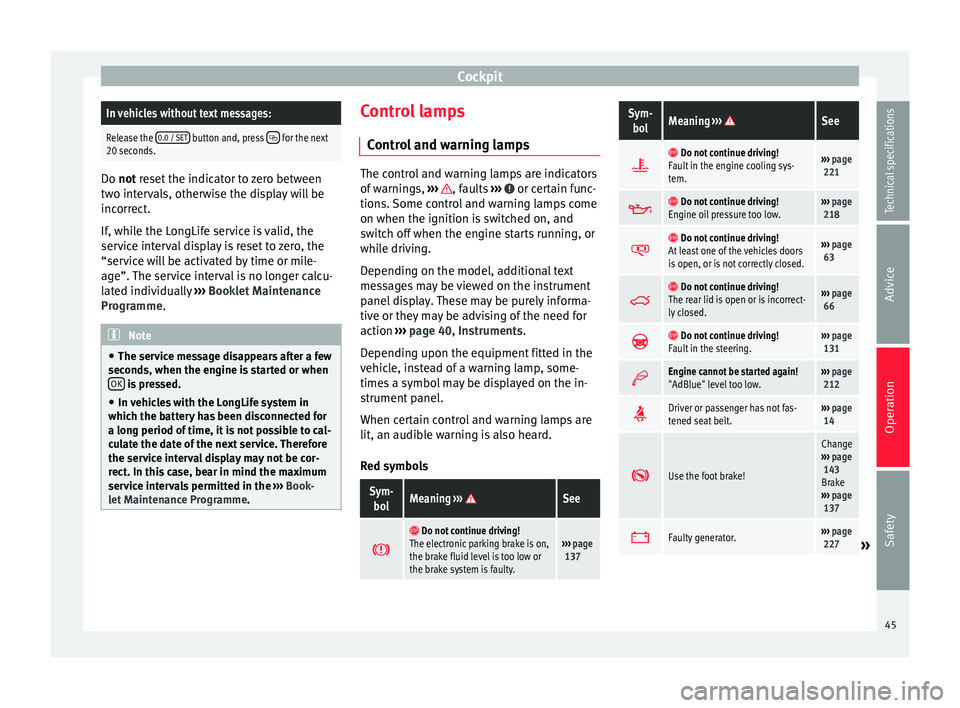
let Maintenance Programme. Control lamps
Control and warning lamps The control and warning lamps are indicators
of warnings,
››› , faults
››› or certain func-
tions. Some control and warning lamps come
on when the ignition is switched on, and
switch off when the engine starts running, or
while driving.
Depending on the model, additional text
messages may be viewed on the instrument
panel display. These may be purely informa-
tive or they may be advising of the need for
action ›››
page 40, Instruments .
D ependin
g upon the equipment fitted in the
vehicle, instead of a warning lamp, some-
times a symbol may be displayed on the in-
strument panel.
When certain control and warning lamps are
lit, an audible warning is also heard.
Red symbols
Sym- bolMeaning ››› See
Do not continue driving!
The electronic parking brake is on,
the brake fluid level is too low or
the brake system is faulty.››› page
137
Sym-
bolMeaning ››› See
Do not continue driving!
Fault in the engine cooling sys-
tem.››› page
221
Do not continue driving!
Engine oil pressure too low.››› page
218
Do not continue driving!
At least one of the vehicles doors
is open, or is not correctly closed.››› page
63
Do not continue driving!
The rear lid is open or is incorrect-
ly closed.››› page
66
Do not continue driving!
Fault in the steering.››› page
131
Engine cannot be started again!
"AdBlue" level too low.›››
page
212
Driver or passenger has not fas-
tened seat belt.›››
page
14
Use the foot brake!
Change
››› page
143
Brake
››› page
137
Faulty generator.›››
page
227» 45
Technical specifications
Advice
Operation
Safety
Page 50 of 305
Operation
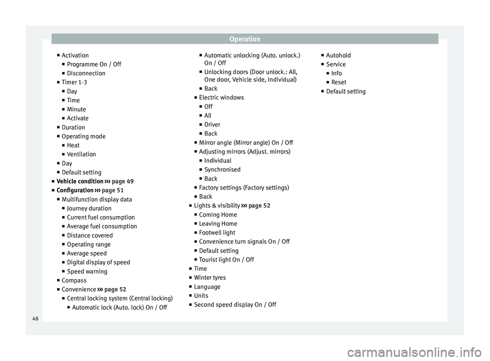
■ Activation
■ Programme On / Off
■ Disconnection
■ Timer 1-3
■ Day
■ Time
■ Minute
■ Activate
■ Duration
■ Operating mode
■ Heat
■ Ventilation
■ Day
■ Default setting
■ Vehicle condition
›
›› page 49
■ Configuration ››› page 51
■ Multifunction display data
■ Journey duration
■ Current fuel consumption
■ Average fuel consumption
■ Distance covered
■ Operating range
■ Average speed
■ Digital display of speed
■ Speed warning
■ Compass
■ Convenience ››› page 52
■ Central locking system (Central locking)
■Automatic lock (Auto. lock) On / Off ■
Automatic unlocking (Auto. unlock.)
On / Off
■ Unlocking doors (Door unlock.: All,
One door, Vehicle side, Individual)
■ Back
■ Electric windows
■ Off
■ All
■ Driver
■ Back
■ Mirror angle (Mirror angle) On / Off
■ Adjusting mirrors (Adjust. mirrors)
■ Individual
■ Synchronised
■ Back
■ Factory settings (Factory settings)
■ Back
■ Lights & visibility ››› page 52
■ Coming Home
■ Leaving Home
■ Footwell light
■ Convenience turn signals On / Off
■ Default setting
■ Tourist light On / Off
■ Time
■ Winter tyres
■ Language
■ Units
■ Second speed display On / Off ■
Autohold
■ Service
■ Info
■ Reset
■ Default setting
48
Page 52 of 305
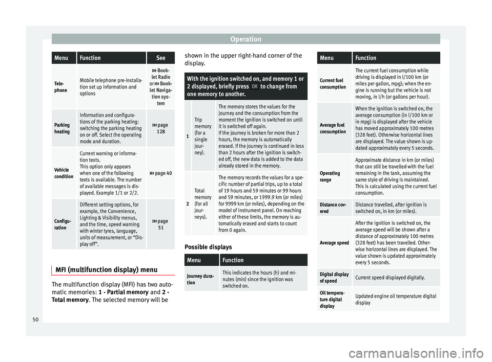
OperationMenuFunctionSee
Tele-
phoneMobile telephone pre-installa-
tion set up information and
options
›››
Book-
let Radio
or ››› Book-
let Naviga- tion sys- tem
Parking
heating
Information and configura-
tions of the parking heating:
switching the parking heating
on or off. Select the operating
mode and duration.
››› page
128
Vehicle
condition
Current warning or informa-
tion texts.
This option only appears
when one of the following
texts is available. The number
of available messages is dis-
played. Example 1/1 or 2/2.
››› page 40
Configu-
ration
Different setting options, for
example, the Convenience,
Lighting & Visibility menus,
and the time, speed warning
with winter tyres, language,
units of measurement, or “Dis-
play off”.
››› page
51 MFI
(multifunction display) menu The multifunction display (MFI) has two auto-
matic memories:
1 - Partial memory and 2 -
T ot
al memory . The selected memory will be shown in the upper right-hand corner of the
display.
With the ignition switched on, and memory 1 or
2 displayed, briefly press
OK to change from
one memory to another.
1
Trip
memory
(for a
single
jour-
ney).
The memory stores the values for the
journey and the consumption from the
moment the ignition is switched on until
it is switched off again.
If the journey is broken for more than 2
hours, the memory is automatically
erased. If the journey is continued in less
than 2 hours after the ignition is switch-
ed off, the new data is added to the data
already stored in the memory.
2
Total
memory
(for all
jour-
neys).
The memory records the values for a spe-
cific number of partial trips, up to a total
of 19 hours and 59 minutes or 99 hours
and 59 minutes, or 1999.9 km (or miles)
for 9999 km (or miles), depending on the
model of instrument panel. On reaching
either of these limits, the memory is au-
tomatically erased and starts to count
from 0 again. Possible displays
MenuFunction
Journey dura-
tionThis indicates the hours (h) and mi-
nutes (min) since the ignition was
switched on.
MenuFunction
Current fuel
consumption
The current fuel consumption while
driving is displayed in l/100 km (or
miles per gallon, mpg); when the en-
gine is running but the vehicle is not
moving, in l/h (or gallons per hour).
Average fuel
consumption
When the ignition is switched on, the
average consumption (in l/100 km or in mpg) is displayed after the vehicle
has moved approximately 100 metres
(328 feet). Otherwise horizontal lines
are displayed. The value shown is up-
dated approximately every 5 seconds.
Operating
range
Approximate distance in km (or miles)
that can still be travelled with the fuel
remaining in the tank, assuming the
same style of driving is maintained.
This is calculated using the current fuel
consumption.
Distance cov-
eredDistance travelled, after ignition is
switched on, in km (or miles).
Average speed
After the ignition is switched on, the
average speed will be shown after a
distance of approximately 100 metres
(328 feet) has been travelled. Other-
wise horizontal lines are displayed. The
value shown is updated approximately
every 5 seconds.
Digital display
of speedCurrent speed displayed digitally.
Oil tempera-
ture digital
displayUpdated engine oil temperature digital
display 50
Page 53 of 305
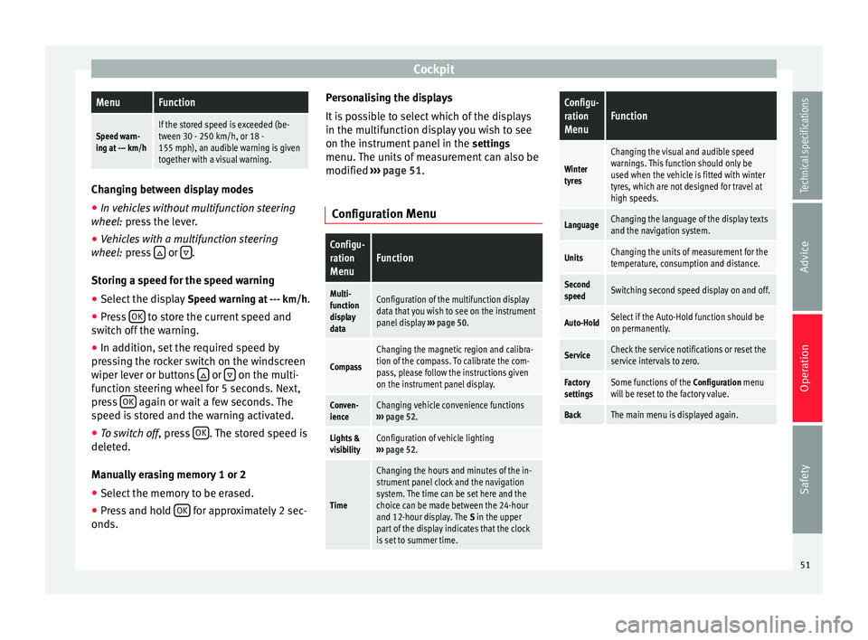
CockpitMenuFunction
Speed warn-
ing at --- km/hIf the stored speed is exceeded (be-
tween 30 - 250 km/h, or 18 -
155 mph), an audible warning is given
together with a visual warning. Changing between display modes
● In vehicles without multifunction steering
wheel: press the lever.
● Vehicle
s with a multifunction steering
wheel:
press or
.
Storing a speed for the speed warning
● Select the display Speed warning at --- km/h
.
● Press OK to store the current speed and
switch off the warning.
● In addition, set the required speed by
pressing the rocker switch on the windscreen
wiper lever or buttons or
on the multi-
function steering wheel for 5 seconds. Next,
press OK again or wait a few seconds. The
speed is stored and the warning activated.
● To switch off , press OK . The stored speed is
deleted.
Manually erasing memory 1 or 2
● Select the memory to be erased.
● Press and hold OK for approximately 2 sec-
onds. Personalising the displays
It is possible to select which of the displays
in the multifunction display you wish to see
on the instrument panel in the
settings
menu. The units of measurement can also be
modified ››› page 51 .
C onfigur
ation Menu
Configu-
ration
MenuFunction
Multi-
function
display
dataConfiguration of the multifunction display
data that you wish to see on the instrument
panel display ››› page 50.
Compass
Changing the magnetic region and calibra-
tion of the compass. To calibrate the com-
pass, please follow the instructions given
on the instrument panel display.
Conven-
ienceChanging vehicle convenience functions
››› page 52.
Lights &
visibilityConfiguration of vehicle lighting
››› page 52.
Time
Changing the hours and minutes of the in-
strument panel clock and the navigation
system. The time can be set here and the
choice can be made between the 24-hour
and 12-hour display. The S in the upper
part of the display indicates that the clock
is set to summer time.
Configu-
ration
MenuFunction
Winter
tyres
Changing the visual and audible speed
warnings. This function should only be
used when the vehicle is fitted with winter
tyres, which are not designed for travel at
high speeds.
LanguageChanging the language of the display texts
and the navigation system.
UnitsChanging the units of measurement for the
temperature, consumption and distance.
Second
speedSwitching second speed display on and off.
Auto-HoldSelect if the Auto-Hold function should be
on permanently.
ServiceCheck the service notifications or reset the
service intervals to zero.
Factory
settingsSome functions of the Configuration menu
will be reset to the factory value.
BackThe main menu is displayed again. 51
Technical specifications
Advice
Operation
Safety
Page 58 of 305
Operation
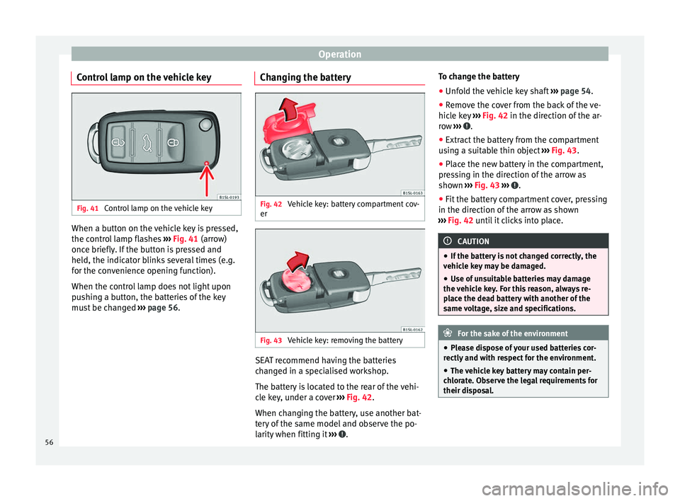
Control lamp on the vehicle key Fig. 41
Control lamp on the vehicle key When a button on the vehicle key is pressed,
the control lamp flashes
››› Fig. 41 (arrow)
onc e briefly
. If the button is pressed and
held, the indicator blinks several times (e.g.
for the convenience opening function).
When the control lamp does not light upon
pushing a button, the batteries of the key
must be changed ››› page 56. Changing the battery Fig. 42
Vehicle key: battery compartment cov-
er Fig. 43
Vehicle key: removing the battery SEAT recommend having the batteries
changed in a specialised workshop.
The battery is located to the rear of the vehi-
cle key, under a cover
››› Fig. 42 .
When c h
anging the battery, use another bat-
tery of the same model and observe the po-
larity when fitting it ››› .To change the battery
●
Unfold the vehicle key shaft ››› page 54.
● Remove the cover from the back of the ve-
hicle key ››› Fig. 42 in the direction of the ar-
r o
w ››› .
● Extract the battery from the compartment
using a suitable thin object ››› Fig. 43 .
● Plac
e the new battery in the compartment,
pressing in the direction of the arrow as
shown ››› Fig. 43 ››› .
● Fit the battery compartment cover, pressing
in the direction of the arrow as shown
››› Fig. 42 until it clicks into place. CAUTION
● If the battery is not changed correctly, the
vehicle key may be damaged.
● Use of unsuitable batteries may damage
the vehicle key. For this reason, always re-
place the dead battery with another of the
same voltage, size and specifications. For the sake of the environment
● Please dispose of your used batteries cor-
rectly and with respect for the environment.
● The vehicle key battery may contain per-
chlorate. Observe the legal requirements for
their disposal. 56