light Seat Altea 2015 Service Manual
[x] Cancel search | Manufacturer: SEAT, Model Year: 2015, Model line: Altea, Model: Seat Altea 2015Pages: 236, PDF Size: 4.23 MB
Page 82 of 236
Operation
Instrument and switch lighting 1When the headlights are switched on, the
brightness of the instrument panel and con-
trols can be adjusted by turning the thumb
wheel
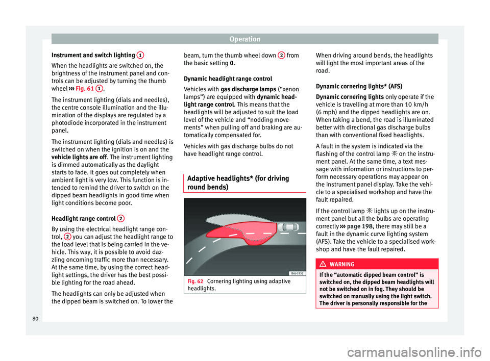
››› Fig. 61 1 .
The instrument lighting (dials and needles),
the centre console illumination and the illu-
mination of the displays are regulated by a
photodiode incorporated in the instrument
panel.
The instrument lighting (dials and needles) is
switched on when the ignition is on and the
vehicle lights are off . The instrument lighting
is dimmed automatically as the daylight
starts to fade. It goes out completely when
ambient light is very low. This function is in-
tended to remind the driver to switch on the
dipped beam headlights in good time when
light conditions become poor.
Headlight range control 2By using the electrical headlight range con-
trol,
2 you can adjust the headlight range to
the load level that is being carried in the ve-
hicle. This way, it is possible to avoid daz-
zling oncoming traffic more than necessary.
At the same time, by using the correct head-
light settings, the driver has the best possi-
ble lighting for the road ahead.
The headlights can only be adjusted when
the dipped beam is switched on. To lower the beam, turn the thumb wheel down
2 from
the basic setting 0.
D y
namic headlight range control
Vehicles with gas discharge lamps (“xenon
lamps”) are equipped with
dynamic head-
light range control . This means that the
headlights will be adjusted to suit the load
level of the vehicle and “nodding move-
ments” when pulling off and braking are au-
tomatically compensated for.
Vehicles with gas discharge bulbs do not
have headlight range control.
Adaptive headlights* (for driving
round bends) Fig. 62
Cornering lighting using adaptive
headlights. When driving around bends, the headlights
will light the most important areas of the
road.
Dynamic cornering lights* (AFS)
Dynamic cornering lights
only operate if the
vehicle is travelling at more than 10 km/h
(6 mph) and the dipped headlights are on.
When taking a bend, the road is illuminated
better with directional gas discharge bulbs
than with conventional fixed headlights.
A fault in the system is indicated via the
flashing of the control lamp on the instru-
ment panel. At the same time, a text mes-
sage with information or instructions to per-
form necessary operations may appear on
the instrument panel display. Take the vehi-
cle to a specialised workshop and have the
fault repaired.
If the control lamp lights up on the instru-
ment panel but all the bulbs are operating
correctly ››› page 198 , there may still be a
f au
lt in the dynamic curve lighting system
(AFS). Take the vehicle to a specialised work-
shop and have the fault repaired. WARNING
If the “automatic dipped beam control” is
switched on, the dipped beam headlights will
not be switched on in fog. They should be
switched on manually using the light switch.
The driver is personally responsible for the 80
Page 83 of 236
Lights and visibility
correct use of lights in all situations. “Auto-
matic headlight control” is merely a system
to support the driver. Where necessary,
switch on the lights manually using the light
switch.
Fog lights with cornering function*
3 Applies to the model: ALTEA / ALTEA XL
When the t urn s
ignal is switched on to turn or
on very tight bends, the right or left fog light
automatically comes on to function as a cor-
nering light. The cornering light only oper-
at e
s if the dipped beam lights are on. WARNING
Read and observe the relevant warnings ››› in Adaptive headlights* (for driving round
bends) on page 80 Hazard warning lights
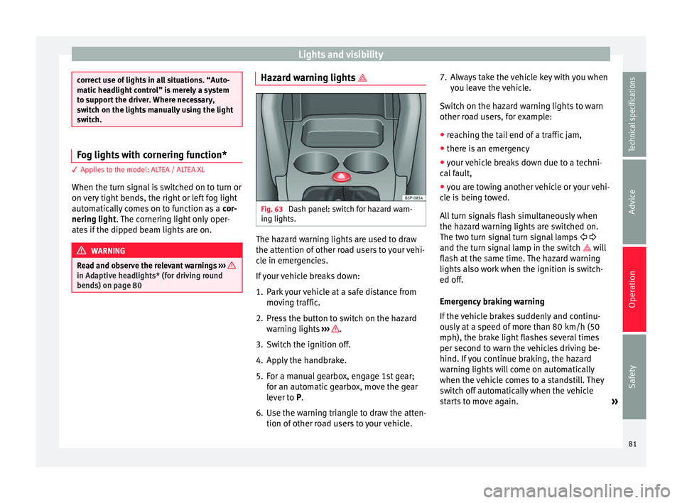
Fig. 63
Dash panel: switch for hazard warn-
ing lights. The hazard warning lights are used to draw
the attention of other road users to your vehi-
cle in emergencies.
If your vehicle breaks down:
1. Park your vehicle at a safe distance from
moving traffic.
2. Press the button to switch on the hazard warning lights ››› .
3. Switch the ignition off.
4. Apply the handbrake.
5. For a manual gearbox, engage 1st gear; for an automatic gearbox, move the gear
lever to P
.
6.
Use the warning triangle to draw the atten-
tion of other road users to your vehicle. 7. Always take the vehicle key with you when
you leave the vehicle.
Switch on the hazard warning lights to warn
other road users, for example:
● reaching the tail end of a traffic jam,
● there is an emergency
● your vehicle breaks down due to a techni-
cal fault,
● you are towing another vehicle or your vehi-
cle is being towed.
All turn signals flash simultaneously when
the hazard warning lights are switched on.
The two turn signal turn signal lamps
and the turn signal lamp in the switch will
flash at the same time. The hazard warning
lights also work when the ignition is switch-
ed off.
Emergency braking warning
If the vehicle brakes suddenly and continu-
ously at a speed of more than 80 km/h (50
mph), the brake light flashes several times
per second to warn the vehicles driving be-
hind. If you continue braking, the hazard
warning lights will come on automatically
when the vehicle comes to a standstill. They
switch off automatically when the vehicle
starts to move again. »
81
Technical specifications
Advice
Operation
Safety
Page 84 of 236
Operation
WARNING
● The risk of an accident increases if your ve-
hicle breaks down. Always use the hazard
warning lights and a warning triangle to draw
the attention of other road users to your sta-
tionary vehicle.
● Never park where the catalytic converter
could come into contact with inflammable
materials under the vehicle, for example dry
grass or spilt petrol. This could start a fire! Note
● The battery will run down if the hazard
warning lights are left on for a long time,
even if the ignition is switched off.
● The use of the hazard warning lights de-
scribed here is subject to the relevant statu-
tory requirements. Interior lights
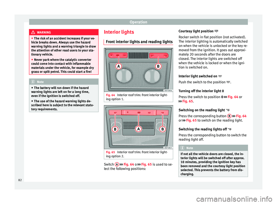
Front interior lights and reading lights Fig. 64
Interior roof trim: front interior light-
ing option 1. Fig. 65
Interior roof trim: front interior light-
ing option 2. Switch
A
››› Fig. 64 o
›
›› Fig. 65 is used to se-
lect the following positions: Courtesy light position
Rocker switch in flat position (not activated).
The interior lighting is automatically switched
on when the vehicle is unlocked or the key re-
moved from the ignition. It goes out approxi-
mately 20 seconds after the doors are
closed. The interior lights are switched off
when the vehicle is locked or when the igni-
tion is switched on.
Interior light switched on
Push the switch to the position
.
Turning off the interior light 0
Press the switch to position 0
››› Fig. 64 or
››› Fig. 65.
Swit
ching on the reading light
Press the corresponding button B
››› Fig. 64
or ››› Fig. 65 to switch on the reading light.
Sw it
ching the reading lights off
Press the corresponding button to switch the
reading light off. Note
If not all the vehicle doors are closed, the in-
terior lights will be switched off after approx.
10 minutes, providing the ignition key has
been removed and the courtesy light position
selected. This prevents the battery from dis-
charging. 82
Page 85 of 236
Lights and visibility
Rear interior lights and reading
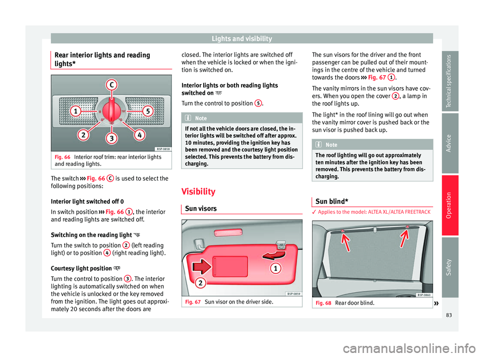
lights* Fig. 66
Interior roof trim: rear interior lights
and reading lights. The switch
››› Fig. 66 C is used to select the
following positions:
Interior light switched off 0
In switch position ››› Fig. 66 1 , the interior
and reading lights are switched off.
Switching on the reading light
Turn the switch to position 2 (left reading
light) or to position 4 (right reading light).
Courtesy light position
Turn the control to position 3 . The interior
lighting is automatically switched on when
the vehicle is unlocked or the key removed
from the ignition. The light goes out approxi-
mately 20 seconds after the doors are closed. The interior lights are switched off
when the vehicle is locked or when the igni-
tion is switched on.
Interior lights or both reading lights
switched on
T urn the c
ontrol to position 5 .
Note
If not all the vehicle doors are closed, the in-
terior lights will be switched off after approx.
10 minutes, providing the ignition key has
been removed and the courtesy light position
selected. This prevents the battery from dis-
charging. Visibility
Sun visors Fig. 67
Sun visor on the driver side. The sun visors for the driver and the front
passenger can be pulled out of their mount-
ings in the centre of the vehicle and turned
towards the doors
››› Fig. 67 1 .
The vanity mirrors in the sun visors have cov-
ers. When you open the cover 2 , a lamp in
the roof lights up.
The light* in the roof lining will go out when
the vanity mirror cover is pushed back or the
sun visor is pushed back up. Note
The roof lighting will go out approximately
ten minutes after the ignition key has been
removed. This prevents the battery from dis-
charging. Sun blind*
3 Applies to the model: ALTEA XL/ALTEA FREETRACK
Fig. 68
Rear door blind.
» 83
Technical specifications
Advice
Operation
Safety
Page 86 of 236

Operation
Rear window sun blind* – Pull out the visor and hook it onto the
hooks at the top of the door frame
››› Fig. 68 .
W ind
screen wiper and rear
window wiper systems
Windscreen wipers Fig. 69
Windscreen wiper lever. Fig. 70
Rain sensor on the windscreen seen
from the interior. The windscreen wiper lever
››› Fig. 69 has the
f o
llowing positions:
Initial position 0 Rest, windscreen disconnected.
Intermittent wipe / automatic wipe with rain
sensor*
– Move the lever up to position 1 .
– With switch A adjust the wipe interval or
sensitivity of the rain sensor*.
Switch A has 4 positions.
The rain sensor* is part of the intermittent
wipe function. You will have to switch the rain
sensor back on if you switch off the ignition.
This is done by switching the wiper interval
wipe function off and back on. Slow wipe
–
Push the lever up to position 2 .
Continuous wipe – Push the lever up to position 3 .
Short wipe – Move the lever down to position 4 to give
the windscreen a short wipe. The wiper will
s t
art to move faster if you keep the lever
pressed down for longer than two seconds.
Automatic wash/wipe
– Pull the lever towards the steering wheel,
position 5 . The wash function will start
immediately and the wipers will start with a
slight delay. The wash and wiper systems
will function at the same time at speeds of
over 120 km/h (75 mph).
– Release the lever. The wipers will keep run-
ning for approximately 4 seconds.
Heated windscreen in the wiper blade area*
In some countries and in some versions, it is
possible to heat the windscreen in the area
of the windscreen wiper blades in order to
aid de-icing in this area. The function is
switched on by pressing the heated rear win-
dow key .
84
Page 87 of 236

Lights and visibility
WARNING
● Worn and dirty wiper blades reduce visibili-
ty and safety levels while driving.
● In cold conditions, you should not use the
wash/wipe system unless you have warmed
the windscreen with the heating and ventila-
tion system. The windscreen washer fluid
could otherwise freeze on the windscreen and
obscure your view of the road.
● The rain sensor may not detect enough rain
to switch on the wipers. If necessary, switch
on the wipers manually when water on the
windscreen impedes visibility.
● Always note the corresponding warnings
››› page 194. CAUTION
In icy conditions, always check that the wiper
blades are not frozen to the glass before us-
ing the wipers for the first time. If you switch
on the windscreen wipers when the wiper
blades are frozen to the windscreen, you
could damage both the wiper blades and the
wiper motor. Note
● The windscreen wipers will only work when
the ignition is switched on.
● In certain versions of vehicles with alarms,
the windscreen wiper will only work when the
ignition is on and the bonnet closed. ●
When in use, the wipers do not go as far as
the rest position. When the lever is moved to
position 0, they are totally hidden.
● If the vehicle stops when wiper speed 2 ›››
Fig. 69 or 3 is selected, the next speed
down will be selected automatically. The set
speed will be resumed when the vehicle pulls
away.
● The windscreen will be wiped again after
approximately five seconds once the “auto-
matic wash/wipe system” has been activa-
ted, provided the vehicle is moving (drip func-
tion). If you activate the wipers less than 3
seconds after the drip function, a new wash
sequence will begin without performing the
last wipe. For the “drip” function to work
again, you have to turn the ignition off and
then on again.
● When the “interval wipe function” is on,
the intervals are directly proportional to the
speed. This way, the higher the vehicle speed
the shorter the intervals.
● The wiper will try to wipe away any obsta-
cles that are on the windscreen. The wiper
will stop moving if the obstacle continues to
block its path. Remove the obstacle and
switch the wiper back on again.
● Before removing any objects that may be
trapped in the side areas of the windscreen,
always move the wiper arms to the service
position (horizontal).
● The heat output of the heated jets is con-
trolled automatically when the ignition is
switched on, depending upon the outside
temperature. ●
Do not put stickers on the windscreen in
front of the rain sensor*. This may cause sen-
sor disruption or faults. Rear window wiper
Fig. 71
Windscreen wiper lever: rear window
wiper. Switching on the interval wipe
– Press the lever forward to position 6 ›››
Fig. 71 . The wiper will wipe the window
ap pr
oximately every 6 seconds.
Switching off the interval wipe function
– Pull the lever back from position 6 toward
the steering wheel. The wiper will continue
to function for a short period if you switch
off whilst the wipers are in motion. »
85
Technical specifications
Advice
Operation
Safety
Page 88 of 236
Operation
Switching on automatic wipe – Press the lever fully forwards to position 7›››
Fig. 71 . The rear wash function will start
immedi at
ely and the wiper will start a few
seconds later. The rear window wash sys-
tem will function as long as you hold the
lever in this position.
– Release the lever. The wiper then wipes for
approximately 4 seconds, and then in inter-
vals again.
– Release the lever. The washer system stops
and the wipers function. WARNING
● Worn and dirty wiper blades reduce visibili-
ty and safety levels while driving.
● Always note the corresponding warnings
on ››› page 194. CAUTION
In icy conditions, always check that the wiper
blade is not frozen to the glass before using
the wiper for the first time. If you switch on
the wiper when the wiper blade is frozen to
the glass, this could damage both the wiper
blade and the wiper motor. Note
● The windscreen wiper will only function
when the ignition is switched on and the rear
lid is closed. ●
In reverse gear, with the windscreen wipers
switched on, the rear windscreen wiper will
make one wipe. Headlight washer*
The headlight washers clean the headlight
lenses.
The headlight washers are activated auto-
matically when the windscreen washer is
used and the window wiper lever is pulled to-
wards the steering wheel for at least 1.5 sec-
onds – provided the dipped beam headlights
or main beams are switched on. Clean off
stubborn dirt (insects, etc.) from the head-
lights at regular intervals, for instance, when
filling the fuel tank.
Note
● To ensure that the headlight washers work
properly in winter, keep the nozzle holders in
the bumper free of snow and remove any ice
with a de-icer spray.
● To remove water, the windscreen wipers
will be activated from time to time, the head-
light washers will be activated every three cy-
cles. Rear vision mirrors
Interior rear vision mirror It is dangerous to drive if you cannot see
clearly through the rear window.
Manual anti-dazzle function for interior rear
vision mirror
In the basic mirror position, the lever at the
bottom edge of the rear vision mirror should
be at the front. Pull the lever to the back to
select the anti-dazzle function.
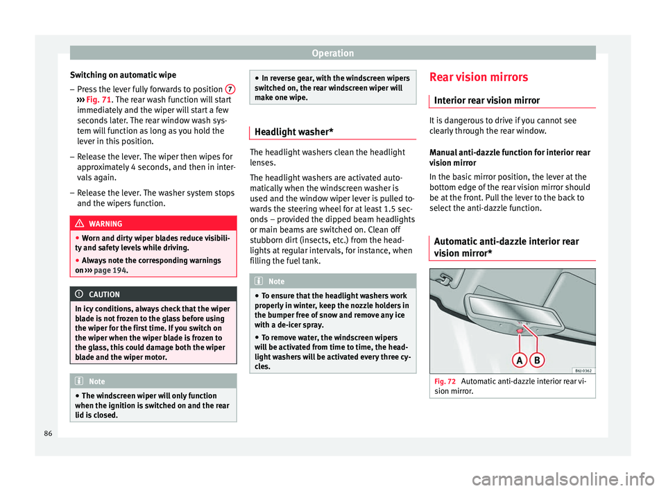
Automatic anti-dazzle interior rear
vision mirror* Fig. 72
Automatic anti-dazzle interior rear vi-
sion mirror. 86
Page 89 of 236

Lights and visibility
Switching off the anti-dazzle function
– Press button A
››› Fig. 72. Control lamp Bgoes off.
Switching on the anti-dazzle function
– Press button A
››› Fig. 72. The control
lamp lights up.
Anti-dazzle function
The anti-dazzle function is activated every
time the ignition is switched on. The green
warning lamp lights up in the rear vision mir-
ror housing.
When the anti-dazzle function is enabled, the
interior rear vision mirror will darken auto-
matically according to the amount of light it
r ec
eives. The anti-dazzle function is cancel-
led if reverse gear is engaged. Note
● The automatic anti-dazzle function will only
work properly if the sun blind* for the rear
window is retracted and there are no other
objects preventing light from reaching the in-
terior rear vision mirror.
● If you have to stick any type of sticker on
the windscreen, do not do so in front of the
sensors. Doing so could prevent the anti-daz-
zle function from working well or even from
working at all. Exterior mirrors
Fig. 73
Exterior mirror controls. The exterior mirrors can be adjusted using
the rotary knob in the centre console.
Basic setting of exterior mirrors
1. Turn knob
››› Fig. 73 to position L (left ex-
t erior mirr
or).
2. Turn the rotary knob to position the exteri- or mirror so that you have a good view to
the rear of the vehicle.
3. Turn the knob to position R (right exterior mirror
).
4. Swivel the rotary knob to position the ex- terior mirror so that you have a good view
to the rear of the vehicle ››› .
Heating the exterior mirrors* – Turn the knob forward ››› Fig. 73 so that the
he at
ed rear vision mirrors warm up and the heated windscreen* in the wiper blade rest
area is activated
››› page 84.
– Exterior mirror heating is not activated in
temperatures above approximately +20 °C
(+68 °F).
Folding in exterior mirrors*
– Turn the control ››› Fig. 73 to position to
fold in the exterior mirrors. You should al-
ways fold in the exterior mirrors if you are
driving through an automatic car wash.
This will help prevent damage.
Folding exterior mirrors with convenience
closing* – The exterior mirror will fold back automati-
cally with convenience closing (with the re-
mote or the key).
– To unfold it again, open the door and
switch on the ignition.
Folding exterior mirrors back out to the
extended position* – Turn the knob to another position to fold
the exterior mirrors back out ››› .
Synchronised mirror adjustment
1. Turn the control to the position L (
left ex-
t
erior mirror).
2. Turn the rotary knob to position the exteri- or mirror so that you have a good view to »
87
Technical specifications
Advice
Operation
Safety
Page 90 of 236
Operation
the rear of the vehicle. The right exterior
mirror will be adjusted at the same time
(sy nc
hronised). WARNING
● Convex or spherical mirrors increase the
field of vision however the objects appear
smaller and further away. If you use these
mirrors to estimate the distance to vehicles
behind you when changing lane, you could
make a mistake. Risk of accident.
● If possible, use the rear vision mirror to es-
timate distances to vehicles behind you.
● Make sure that you do not get your finger
trapped between the mirror and the mirror
base when folding back the mirrors. Risk of
injury! For the sake of the environment
The exterior mirror heating should be switch-
ed off when it is no longer needed. Other-
wise, it is an unnecessary fuel waste. Note
● If the electrical adjustment ever fails to op-
erate, the mirrors can be adjusted by hand by
lightly pressing the edge of the mirror glass.
● In vehicles with electric exterior mirrors,
the following points should be observed: if, due to an external force (e.g. being knocked
while manoeuvring), the adjustment of the
mirror housing is altered, the mirror will have
to be fully folded electrically. Do not readjust the rear vision mirror housing by hand, as
this will interfere with the mirror adjuster
function.
● The rear vision mirrors can be adjusted sep-
arately or simultaneously, as described
above.
● The folding function on the exterior mirrors
is not active at speeds over 40 km/h
(25 mph). Seats and head restraints
Adjusting the seat and head
restraints
The importance of correct seat
adjustment Proper seat adjustment optimises the level of
protection offered by seat belts and airbags.
Your vehicle has
five
seats, two in the front
and thr ee in the r
ear. Each seat is equipped
with a three-point seat belt.
The driver seat and the front passenger seat
can be adjusted in many ways to suit the
physical requirements of the vehicle occu-
pants. The correct seat position is very impor-
tant for:
● a fast and easy operation of all controls on
the instrument panel,
● a relaxed posture which does not cause
drowsiness,
● a safe driving ›››
page 5,
● ensuring that the seat belts and airbag sys-
tem provide maximum protection ›››
page 11. WARNING
● If the driver and passengers assume im-
proper sitting positions, they may sustain
critical injuries. 88
Page 98 of 236
Operation
● in the side trims of the luggage compart-
ment,
● in the spare wheel recess in the luggage
compartment (only on vehicles with an op-
tional anti-puncture kit*.
The clothes hooks are located on the rear
roof handles. WARNING
● Do not store loose objects on the dash pan-
el. These objects could be flung through the
passenger compartment when the vehicle is
moving (e.g. while accelerating, braking or
cornering) and distract the driver.
● Ensure that no objects can fall from the
centre console or other storage compart-
ments into the driver footwell while the vehi-
cle is moving. In the event of a sudden brak-
ing manoeuvre, you will not be able to use
the brake, clutch or accelerator. Risk of acci-
dent.
● Clothing hung on the coat hooks must not
restrict the driver's view. Risk of accident.
The coat hooks are intended only for use with
light articles of clothing. Do not leave any
hard, sharp or heavy objects in hanging arti-
cles of clothing. During sudden braking ma-
noeuvres or accidents, especially those in-
volving airbag deployment, these objects
could injure the vehicle occupants. Multi-purpose mobile storage
compartment*
General information Fig. 91
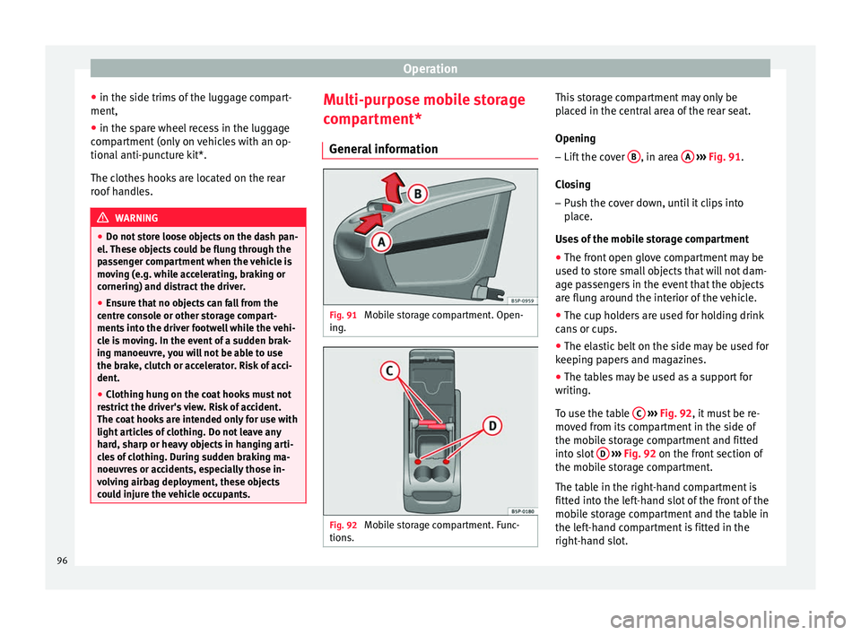
Mobile storage compartment. Open-
ing. Fig. 92
Mobile storage compartment. Func-
tions. This storage compartment may only be
placed in the central area of the rear seat.
Opening
– Lift the cover B , in area
A
››› Fig. 91 .
C lo
sing
– Push the cover down, until it clips into
place.
Uses of the mobile storage compartment
● The front open glove compartment may be
used to store small objects that will not dam-
age passengers in the event that the objects
are flung around the interior of the vehicle.
● The cup holders are used for holding drink
cans or cups.
● The elastic belt on the side may be used for
keeping papers and magazines.
● The tables may be used as a support for
writing.
To use the table C
››› Fig. 92 , it must be re-
mo v
ed from its compartment in the side of
the mobile storage compartment and fitted
into slot D
››› Fig. 92 on the front section of
the mo b
ile storage compartment.
The table in the right-hand compartment is
fitted into the left-hand slot of the front of the
mobile storage compartment and the table in
the left-hand compartment is fitted in the
right-hand slot.
96