rear Seat Ibiza ST 2015 Service Manual
[x] Cancel search | Manufacturer: SEAT, Model Year: 2015, Model line: Ibiza ST, Model: Seat Ibiza ST 2015Pages: 248, PDF Size: 4.77 MB
Page 82 of 248
Emergencies
●
As the driv er of
the towing vehicle:
– Accelerate with particular care and cau-
tion.
– Avoid sudden braking and manoeuvres.
– Brake earlier than usual and more
smoothly. CAUTION
When tow-starting, fuel could enter the cata-
lytic con
verter and damage it. Note
● Ob ser
ve legal requirements when towing or
tow-starting.
● Switch on the hazard warning lights of both
vehicl
es. However, observe any regulations
to the contrary.
● For technical reasons, vehicles with an au-
tomatic
gearbox must not be tow-started.
● If there is no lubricant in the gearbox as the
res
ult of a fault, you must raise the driven
wheels while the vehicle is being towed.
● If the vehicle has to be towed more than
50 km (30 mile
s), the front wheels should be
raised during towing, and towing should be
carried out by a qualified person.
● The steering wheel is locked when the vehi-
cle h
as no electrical power. The vehicle must
then be towed with the front wheels raised.
Towing should be carried out by a qualified
person. ●
The to wline anc
horage should always be
kept in the vehicle. Towline anchorages
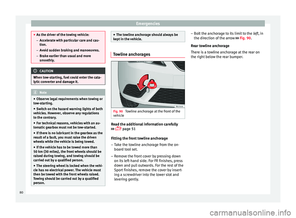
Fig. 90
Towline anchorage at the front of the
v ehic
l
e Read the additional information carefully
› ›
›
page 51
Fitting the front towline anchorage
– Take the towline anchorage from the on-
board t
ool set.
– Remove the front cover by pressing down
on its lef
t-hand side. For FR finishes, press
down and pull outwards. For the rest of the
Sport finishes, remove the cover by insert-
ing a screwdriver into the lower slot and
levering gently. –
Bolt the anc
horage to its limit to the left, in
the direction of the arrow ››› Fig. 90.
Rear towline anchorage
There is a towline anchorage at the rear on
the right below the rear bumper. 80
Page 84 of 248
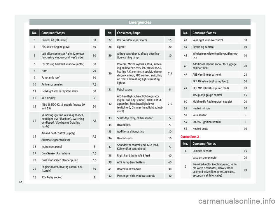
EmergenciesNo.Consumer/Amps
3Power C63 (30 Power)30
4PTC Relay (Engine glow)50
5Left pillar connector A pin 22 (motor
for closing window on driver's side)30
6For closing back left window (motor)30
7Horn20
9Panoramic roof30
10Active suspension7.5
11Headlight washer system relay30
12MIB display5
13(RL-15) SIDO Kl.15 supply (inputs 29
and 55)30
14
Removing ignition key, diagnostics,
headlight lever (flashers), switching
on dipped /side beams (rotating
lights)
7.5
15Air and heat control (supply)7.5Automatic gearbox lever
16Instrument panel5
17Dwa Sensor, Alarm horn7.5
23Dual windscreen cleaner pump7.5
24Engine heater, heating control box
(supply)30
2612V Relay socket5
No.Consumer/Amps
27Rear window wiper motor15
28Lighter20
29Airbag control unit, airbag deactiva-
tion warning lamp10
30
Reverse, Mirror joysticks, RKA, switch-
ing on heated seats, int. pressure A.C,
heating A.C. controls (supply), electro-
chromic mirror, PDC control, switching
on front and rear fog lights (rotating
lights).
7.5
31Petrol gauge5
32
AFS headlights, headlight regulator
(signal and adjustment), LWR Cent, di-
agnostics, front headlight lever
(switch on), Dimmer (headlight adjust-
ment)
7.5
33Start-Stop relay, clutch sensor5
34Heated jets5
35Additional diagnostics10
36Heated seats10
37Soundaktor control feed, GRA feed,
Kühlerlüfter central feed5
38Right hand lights A/66 feed40
39ABS Pump (rear battery)40
41Heated rear window30
42Passenger side window controls30
No.Consumer/Amps
43Rear right window control30
44Reversing camera10
45Windscreen wiper feed lever, diagnos-
tics10
46Additional electric socket for luggage
compartment20
47ABS Ventil (rear battery)25
49
EKP TDI relay (fuel pump feed)30
EKP MPI relay (fuel pump feed)20
TFSI pump gauge control15
50Multimedia Radio (power supply)20
51Heated mirrors10
53Rain sensor5
5430 ZAS (ignition switch)5
55Heated seats10
Control box 2
No.Consumer/Amps
1Lambda sensors15
2
Vacuum pump motor20
Pre-wired motor (coolant pump, varia-
ble valve distributor, active carbon
solenoid valve filter, pressure valve,
secondary air inlet valve)
10
82
Page 91 of 248
Fuses and bulbs
Changing the tail light bulbs S umm
ar
y of LED tail lights3 Applies to the model: IBIZA/IBIZA SC
LED
● Br ak
e lights
● Side lights
Bul
bs
● Retro fog light
● Reverse lights
● Turn signal
Tail light summary 3 App
lies to the model: IBIZA ST
T
ail lights on side panel Bulb lamps
● Brake lights
● Side lights
● Turn signal
Lights on the r
ear lid Bulb lamps
● Reverse lights
● Side lights
● Fog lights Tail lights on side panel LED lamps
●
Brake light (LED)
● Side light (LED)
● Turn signal
Lights on the r
ear lid LED lamps
● Reverse lights
● Side light (LED)
● Fog lights
Access to tail lights 3 App
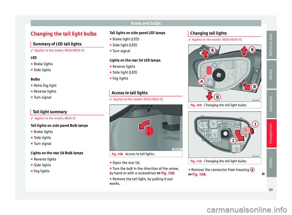
lies to the model: IBIZA/IBIZA SC Fig. 108
Access to tail lights. ●
Open the rear lid.
● Turn the bolt in the direction of the arrow,
b y
h
and or with a screwdriver ››› Fig. 108.
● Remove the tail light, by pulling it out-
ward
s. Changing tail lights 3 Applies to the model: IBIZA/IBIZA SC
Fig. 109
Changing the tail light bulbs Fig. 110
Changing the tail light bulbs ●
Remove the connector from housing A ›››
Fig. 108. »
89
Technical data
Advice
Operation
Emergencies
Safety
Page 92 of 248
Emergencies
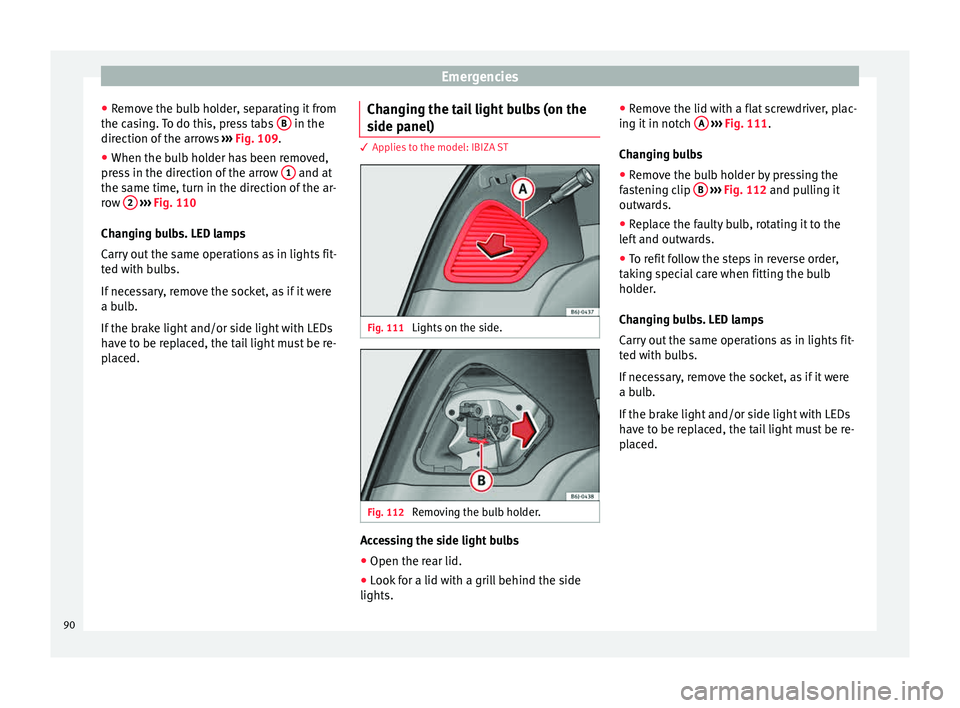
● Remo
v
e the bulb holder, separating it from
the casing. To do this, press tabs B in the
dir ection of
the arr
ows ››› Fig. 109.
● When the bulb holder has been removed,
pres
s in the direction of the arrow 1 and at
the s ame time, t
urn in the dir
ection of the ar-
row 2
› ››
Fig. 110
Ch an
ging bulbs. LED lamps
Carry out the same operations as in lights fit-
ted with bulbs.
If necessary, remove the socket, as if it were
a bulb.
If the brake light and/or side light with LEDs
have to be replaced, the tail light must be re-
placed. Changing the tail light bulbs (on the
side panel) 3 Applies to the model: IBIZA ST
Fig. 111
Lights on the side. Fig. 112
Removing the bulb holder. Accessing the side light bulbs
● Open the rear lid.
● Look for a lid with a grill behind the side
lights. ●
Remo
v
e the lid with a flat screwdriver, plac-
ing it in notch A
› ››
Fig. 111
.
Ch
anging bulbs
● Remove the bulb holder by pressing the
fas
tening clip B
› ››
Fig. 112
and p ulling it
outwards.
● Replace the faulty bulb, rotating it to the
left
and outwards.
● To refit follow the steps in reverse order,
takin
g special care when fitting the bulb
holder.
Changing bulbs. LED lamps
Carry out the same operations as in lights fit-
ted with bulbs.
If necessary, remove the socket, as if it were
a bulb.
If the brake light and/or side light with LEDs
have to be replaced, the tail light must be re-
placed.
90
Page 93 of 248
Fuses and bulbs
Changing the tail light bulbs (on the
r e
ar lid) 3 Applies to the model: IBIZA ST
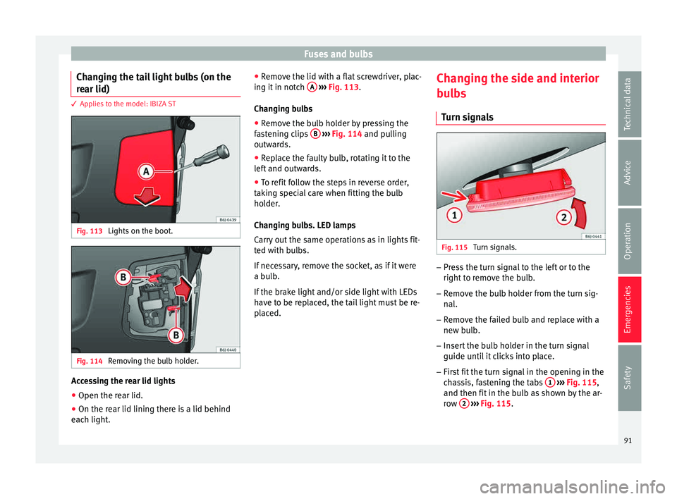
Fig. 113
Lights on the boot. Fig. 114
Removing the bulb holder. Accessing the rear lid lights
● Open the rear lid.
● On the rear lid lining there is a lid behind
e ac
h light
. ●
Remov
e the lid with a flat screwdriver, plac-
ing it in notch A
› ››
Fig. 113
.
Ch
anging bulbs
● Remove the bulb holder by pressing the
fas
tening clips B
› ››
Fig. 114
and p ulling
outwards.
● Replace the faulty bulb, rotating it to the
left
and outwards.
● To refit follow the steps in reverse order,
takin
g special care when fitting the bulb
holder.
Changing bulbs. LED lamps
Carry out the same operations as in lights fit-
ted with bulbs.
If necessary, remove the socket, as if it were
a bulb.
If the brake light and/or side light with LEDs
have to be replaced, the tail light must be re-
placed. Changing the side and interior
bul
bs
Turn signals Fig. 115
Turn signals. –
Press the turn signal to the left or to the
right t
o r
emove the bulb.
– Remove the bulb holder from the turn sig-
nal.
– R
emove the failed bulb and replace with a
new bul
b.
– Insert the bulb holder in the turn signal
guide until
it clicks into place.
– First fit the turn signal in the opening in the
cha
ssis, fastening the tabs 1
› ›
› Fig. 115 ,
and then fit in the bulb as shown by the ar-
row 2
› ›
› Fig. 115
.
91
Technical data
Advice
Operation
Emergencies
Safety
Page 99 of 248
Instruments and warning/control lamps
CAUTION
● To pr ev
ent damage to the engine, the rev
counter needle should only remain in the red
zone for a short period of time.
● When the engine is cold, avoid high revs
and heavy ac
celeration and do not make the
engine work hard. For the sake of the environment
Changing up a gear in time reduces fuel con-
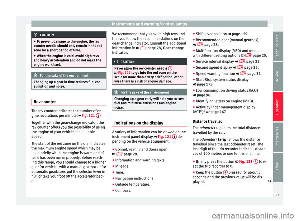
sumption and noi se.Rev counter
The rev counter indicates the number of en-
gine r
ev
o
lutions per minute ›››
Fig. 121 1 .
T og
ether w
ith the gear-change indicator, the
rev counter offers you the possibility of using
the engine of your vehicle at a suitable
speed.
The start of the red zone on the dial indicates
the maximum engine speed which may be
used briefly when the engine is warm and af-
ter it has been run in properly. Before reach-
ing this range, you should change to a higher
gear for vehicles with a manual gearbox or for
automatic gearboxes put the selector lever in
“D” or take your foot off the accelerator ped-
al. We recommend that you avoid high revs and
that
you follow the recommendations on the
gear-change indicator. Consult the additional
information in ›››
page 28, Gear-change
indicator. CAUTION
Never allow the rev counter needle 1 ›››
Fig. 121 to g o int
o the red zone on the
scale for more than a very brief period, other-
wise there is a risk of engine damage. For the sake of the environment
Changing up a gear early will help you to save
fuel and minimi
se emissions and engine
noise. Indications on the display
A variety of information can be viewed on the
in
s
trument
panel display ›››
Fig. 121 3 de-
pendin g on the
v
ehicle equipment:
● Bonnet, rear lid and doors open
›››
page 28.
● Information and warning texts.
● Mileage.
● Time.
● Navigation instructions.
● Outside temperature.
● Compass. ●
Shift l
ever position ››› page 159.
● Recommended gear (manual gearbox)
›››
page 28.
● Multifunction display (MFD) and menus
with differ
ent setting options ›››
page 25.
● Service interval display ›››
page 33.
● Second speed display ›››
page 25.
● Speed warning function ›››
page 32.
● Start-Stop system status display
›››
page 173.
● Low consumption driving status (ECO)
›››
page 98
● Identifying letters on engine (MKB).
● Active cylinder management display
(ACT ®
)* ››
› page 167
Distance travelled
The odometer registers the total distance
travelled by the car.
The odometer (trip ) shows the distance
travelled since the last odometer reset. The
last digit of the trip recorder indicates distan-
ces of 100 metres or one tenths of a mile.
● Briefly press the button ›››
Fig. 121 4 to re-
set the trip r
ec
order to 0.
● Keep the button 4 pressed for about 3
sec ond
s
and the previous value will be dis-
played. »
97
Technical data
Advice
Operation
Emergencies
Safety
Page 104 of 248
Operation
WARNING
● Alw a
ys drive according to the road weather
conditions, the terrain and traffic. Driving rec-
ommendations should never lead to illegal
manoeuvres in surrounding traffic.
● The diesel engine particulate filter may
reac
h extremely high temperatures; in this
case the vehicle should be parked so that it
does not enter into contact with highly flam-
mable materials underneath the vehicle. Oth-
erwise there is a risk of fire. Engine oil pressure
If this warning lamp
is
r
ed it indicates
that the engine oil pressure is too low.
If this warning symbol starts to flash, and is
accompanied by three audible warnings,
switch off the engine and check the oil level.
If necessary, add more oil ›››
page 206.
If the warning lamp flashes although the oil
level is correct, stop driving. Do not even run
the engine at idle speed! Obtain technical as-
sistance.
Checking the oil level
If the warning lamp is yellow the engine
oil level should be checked as soon as possi-
ble. Top up the oil ›››
page 206 at the next
opportunity. Oil level sensor faulty*
If the
y
ellow warning lamp flashes, take
the vehicle to a specialised workshop to have
the oil level sensor checked. Until then it is
advisable to check the oil level every time
you refuel.
Lamp fault* The warning lamp lights up when there is
a f
au
lt on the turn signals, headlights, side
lights and fog lights.
Windscreen washer fluid* This warning lamp lights up to indicate that
the w
ind
s
creen washer level is very low.
This serves as a reminder to fill up the reser-
voir at the earliest opportunity ›››
page 209.
Rear fog light* The warning lamp lights
up when the r
e
ar
fog light is switched on. For further informa-
tion see ›››
page 123. Anti-lock brake system (ABS)* The control lamp
lights up for a f
ew sec-
onds when the ignition is switched on. It
goes out again after the system has run
through an automatic test sequence.
There is a fault in the ABS if:
● The control lamp does not
light up when
the ignition is switched on.
● The control lamp does not go out again af-
ter a few sec
onds.
● The control lamp lights up when the vehicle
is mo
ving.
The vehicle can still be braked in the normal
way, without the ABS function. Take the vehi-
cle to a specialised workshop as soon as
possible. For further information on the ABS
see the ›››
page 171.
If there is a fault in the ABS, the ESC* and the
tyre pressure control lamp will also light up.
Brake system fault
If the ABS warning lamp lights up together
with the brake warning lamp , there is a
fault in the ABS function and in the brake
system ››› .
102
Page 105 of 248
Instruments and warning/control lamps
WARNING
● Bef or
e opening the bonnet, read and ob-
serve the warnings ››› page 201, Working in
the engine compartment.
● If the brake system warning lamp should
light
up together with the ABS warning lamp
, stop the vehicle immediately and check
the brake fluid level in the reservoir
››› page 208, Brake fluid. If the brake fluid
level has dropped below the “MIN” mark you
must not drive on. Risk of accident. Obtain
technical assistance.
● If the brake fluid level is correct, the fault in
the brake sy
stem may have been caused by a
failure of the ABS system. This could cause
the rear wheels to lock quickly when you
brake. This could cause the rear to break
away. Risk of skidding. Stop the vehicle and
seek technical assistance. Differential lock fault (EDS)*
The EDL operates along with the ABS in vehi-
c
l
e
s equipped with Electronic Stability Con-
trol (ESC)*.
A malfunction in the EDL is indicated by the
ABS control lamp . Take the vehicle to a
specialised workshop as soon as possible.
For further information on the EDL see
››› page 170, Electronic differential lock
(EDS)*. Traction control system (ASR)* / The traction control system prevents the driv-
en wheels
fr
om spinning when the vehicle is
accelerating.
There are two control lamps for the traction
control system: and . Both control lamps
light up together when the ignition is switch-
ed on and should turn off after approximately
2 seconds. This is the time taken for the func-
tion check.
The lamp has the following function:
● It flashes when the ASR is working if the ve-
hicl e i
s moving.
If the system is deactivated or if it has any
fault, the warning lamp will remain lit. The
warning lamp will also light up if a fault
should occur in the ABS because the ASR op-
erates in conjunction with the ABS. For fur-
ther information, see ›››
page 172.
The lamp provides information about the
disconnection status of the system:
● It stays lit when the ASR is disconnected
via E
asy Connect.
By means of Easy Connect, the ASR function
is reactivated and the warning lamp switched
off. Electronic Stability Control (ESC)*
/ There are two control lamps for the electronic
st
ab
ility control. The lamp provides infor-
mation concerning function and disconnec-
tion status.
Both control lamps light up together when
the ignition is switched on and should turn
off after approximately 2 seconds. This is the
time taken for the function check.
This programme includes the ABS, EDL and
ASR. It also includes emergency braking as-
sistance (BAS).
The control lamp has the following func-
tions:
● It flashes whilst driving when the ASR/ESC
is activ
ated.
● It will light up if there is a fault in the ESC.
● As the ESC operates in conjunction with the
ABS, the ESC light
will also come on if a fault
should occur in the ABS.
If the ESC control lamp lights up and stays
on after the engine is started, this may mean
that the control system has temporarily
switched off the ESC. In this case the ESC can
be reactivated by switching the ignition off
and then on again. If the control lamp goes
out, this means the system is fully functional. »
103
Technical data
Advice
Operation
Emergencies
Safety
Page 106 of 248
Operation
The l amp provides information about the
di s
connection status of the system:
● It stays lit when the ASR is disconnected on
pres
sing the switch or if we select ESC
Sport mode, only by means of Easy Connect.
Brake system* Situations in which the warning lamp lights
up
●
the brake fluid level is too low
› ››
page 208.
● there is a fault in the brake system.
This w
arning lamp can light up together with
the ABS system warning lamp. WARNING
● If the br ak
e warning lamp does not go out
or if it lights up when driving, the brake fluid
level in the reservoir is too low so there is a
risk of an accident ››› page 208, Brake fluid.
Stop the vehicle and do not drive on. Obtain
technical assistance.
● If the brake warning lamp lights up to-
gether w
ith the ABS lamp this could be
due to an ABS fault. This could cause the rear
wheels to lock quickly when you brake. This
could cause the rear to break away. Risk of
skidding. Stop the vehicle and seek technical
assistance. Cruise speed (cruise control system)*
The warning lamp
comes
on when the
cruise control system is switched on. For fur-
ther information on the cruise control system
please see ›››
page 34.
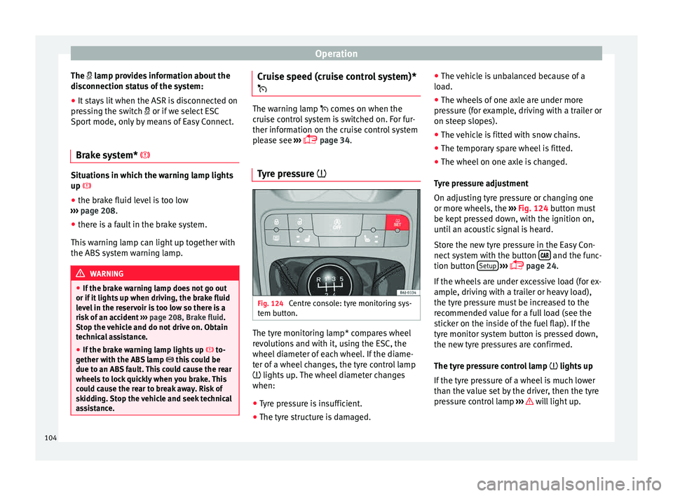
Tyre pressure Fig. 124
Centre console: tyre monitoring sys-
t em b
utt
on. The tyre monitoring lamp* compares wheel
r
ev
o
lutions and with it, using the ESC, the
wheel diameter of each wheel. If the diame-
ter of a wheel changes, the tyre control lamp
lights up. The wheel diameter changes
when:
● Tyre pressure is insufficient.
● The tyre structure is damaged. ●
The vehic
le is unbalanced because of a
load.
● The wheels of one axle are under more
pres
sure (for example, driving with a trailer or
on steep slopes).
● The vehicle is fitted with snow chains.
● The temporary spare wheel is fitted.
● The wheel on one axle is changed.
Tyr
e pressure adjustment
On adjusting tyre pressure or changing one
or more wheels, the ››› Fig. 124 button must
be kept pressed down, with the ignition on,
until an acoustic signal is heard.
Store the new tyre pressure in the Easy Con-
nect system with the button and the func-
tion b utt
on Set
up
› ›
›
page 24.
If the wheels are under excessive load (for ex-
ample, driving with a trailer or heavy load),
the tyre pressure must be increased to the
recommended value for a full load (see the
sticker on the inside of the fuel flap). If the
tyre monitor system button is pressed down,
the new tyre pressures are confirmed.
The tyre pressure control lamp lights up
If the tyre pressure of a wheel is much lower
than the value set by the driver, then the tyre
pressure control lamp ››› will light up.
104
Page 109 of 248
Introduction to the Easy Connect system*
same time when the hazard warning lights
ar e sw
it
ched on.
If any of both turn signals fails, the warning
lamp will start flashing twice faster than nor-
mal.
For further information on the turn signals,
please see ››› page 125.
Electronic immobiliser “SAFE”* This warning lamp flashes if an unauthorised
k
ey
i
s used.
Inside the key there is a chip that deactivates
the electronic immobiliser automatically
when the key is inserted into the ignition.
The electronic immobiliser will be activated
again automatically as soon as you pull the
key out of the ignition lock.
If the following message* is shown on the in-
strument panel display: SAFE, the vehicle
cannot be started.
The engine can, however, be started if the
appropriate coded SEAT genuine key is used. Note
The vehicle cannot operate properly if you do
not h av
e a genuine SEAT key. Introduction to the Easy
C
onnect
sy
stem*
System settings (CAR)* CAR menu (Setup) Read the additional information carefully
›› ›
page 24
To select the settings menus, press the Easy
Connect button and the
Set
up function
b utt
on.
The act
ual number of menus available and
the name of the various options in these me-
nus will depend on the vehicle’s electronics
and equipment.
Pressing the menu button will always take
you to the last menu used.
When the function button check box is activa-
ted , the function is active.
Pressing the menu button will always take
y ou t
o the l
ast menu used.
Any changes made using the settings menus
are automatically saved on closing those me-
nus.
Function buttons in the vehicle’s settings
menuPage
ESC system››› page 169
Tyres››› page 104
Driver assistance››› table on page 24
Parking and manoeuvring››› page 176
Vehicle lights››› table on page 24
Rear vision mirrors and wind-
screen wipers››› table on page 24
Opening and closing››› table on page 24
Multifunction display››› table on page 24
Date and time››› table on page 24
Units››› table on page 24
Service››› page 97
Factory settings››› table on page 24 WARNING
Any distraction may lead to an accident, with
the risk of
injury. Operating the Easy Connect
system while driving could distract you from
traffic. 107
Technical data
Advice
Operation
Emergencies
Safety