rear Seat Ibiza ST 2015 User Guide
[x] Cancel search | Manufacturer: SEAT, Model Year: 2015, Model line: Ibiza ST, Model: Seat Ibiza ST 2015Pages: 248, PDF Size: 4.77 MB
Page 21 of 248
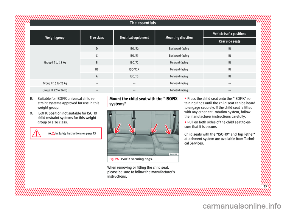
The essentialsWeight groupSize classElectrical equipmentMounting directionVehicle Isofix positions
Rear side seats
Group I 9 to 18 kg
DISO/R2Backward-facingIU
CISO/R3Backward-facingIU
BISO/F2Forward-facingIU
B1ISO/F2XForward-facingIU
AISO/F3Forward-facingIU
Group II 15 to 25 kg------Forward-facing---
Group III 22 to 36 kg------Forward-facing---
Suitable for ISOFIX universal child re-
s
tr
aint
systems approved for use in this
weight group.
ISOFIX position not suitable for ISOFIX
child restraint systems for this weight
group or size class.
››› in Safety instructions on page 73 IU:
X:
Mount the child seat with the “ISOFIX
sy
s
t
ems” Fig. 26
ISOFIX securing rings. When removing or fitting the child seat,
p
l
e
ase be sure to follow the manufacturer's
instructions. ●
Pres
s the child seat onto the “ISOFIX” re-
taining rings until the child seat can be heard
to engage securely. If the child seat is fitted
with any other anti-rotation system, follow
the manufacturer instructions carefully.
● Pull on both sides of the child seat to en-
sure th
at it is secure.
Child seats with the “ISOFIX” and Top Tether*
attachment system are available from Techni-
cal Services. 19
Page 22 of 248
The essentials
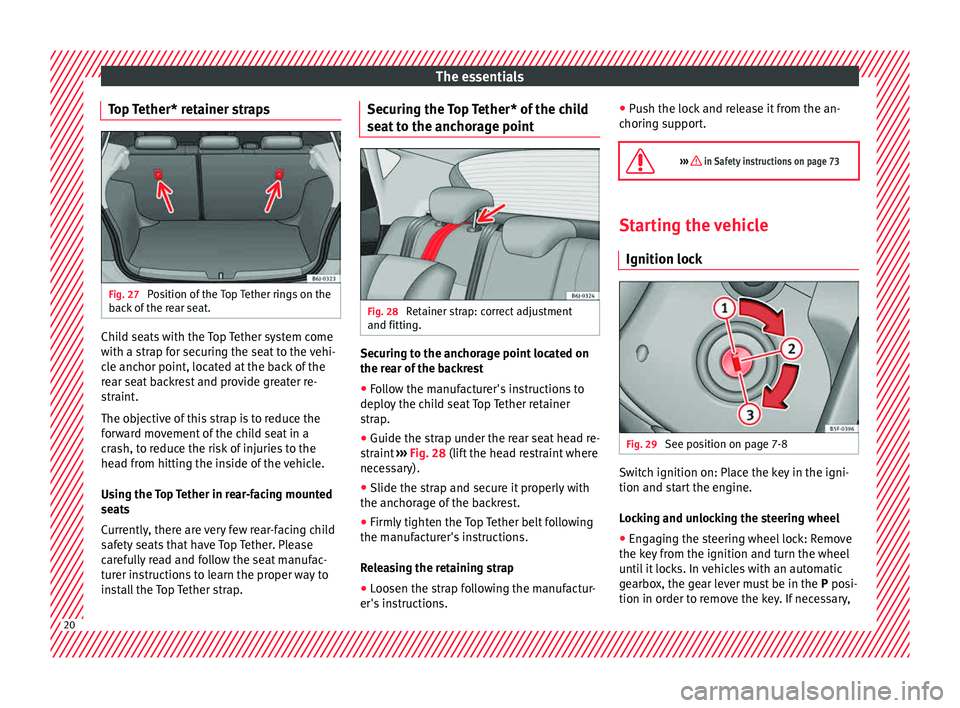
Top Tether* retainer straps Fig. 27
Position of the Top Tether rings on the
b ac
k
of the rear seat. Child seats with the Top Tether system come
w
ith a s
tr
ap for securing the seat to the vehi-
cle anchor point, located at the back of the
rear seat backrest and provide greater re-
straint.
The objective of this strap is to reduce the
forward movement of the child seat in a
crash, to reduce the risk of injuries to the
head from hitting the inside of the vehicle.
Using the Top Tether in rear-facing mounted
seats
Currently, there are very few rear-facing child
safety seats that have Top Tether. Please
carefully read and follow the seat manufac-
turer instructions to learn the proper way to
install the Top Tether strap. Securing the Top Tether* of the child
seat t
o the anchorage point Fig. 28
Retainer strap: correct adjustment
and fittin g. Securing to the anchorage point located on
the r
e
ar of
the backrest
● Follow the manufacturer's instructions to
deploy
the child seat Top Tether retainer
strap.
● Guide the strap under the rear seat head re-
straint
››› Fig. 28 (lift the head restraint where
necessary).
● Slide the strap and secure it properly with
the anchorag
e of the backrest.
● Firmly tighten the Top Tether belt following
the manufact
urer's instructions.
Releasing the retaining strap
● Loosen the strap following the manufactur-
er's ins
tructions. ●
Push the loc
k and release it from the an-
choring support.
››› in Safety instructions on page 73 Starting the vehicle
Ignition lock Fig. 29
See position on page 7-8 Switch ignition on: Place the key in the igni-
tion and s
t
ar
t the engine.
Locking and unlocking the steering wheel
● Engaging the steering wheel lock: Remove
the key fr
om the ignition and turn the wheel
until it locks. In vehicles with an automatic
gearbox, the gear lever must be in the P posi-
tion in order to remove the key. If necessary, 20
Page 23 of 248
The essentials
press the locking key on the selector lever
and r el
e
ase it again.
● Unlocking the steering wheel: Put the key
into the ignition and turn it
at the same time
as the steering wheel in the direction indica-
ted by the arrow. If it is not possible to turn
the steering wheel, it may be because it is
locked.
Turning on/switching off the ignition, glow
plugs reheating
● Switch ignition on: Turn the key to the 2position.
●
Switch ignition off. Turn the key to the 1position.
●
Diesel vehicles : The glo
w p
lugs reheat
when the ignition is switched on
Starting the engine
● Manual gearbox: press the clutch pedal all
the way
down and move the gearbox lever in-
to neutral.
● Automatic gearbox: Press the brake pedal
and move the sel
ector lever to the P position
or into N.
● Turn the key to the 3 position. The key au-
t om
atic
ally returns to the 2 position. Do not
pr e
s
s the accelerator. Start-Stop System*
When you s
top and release the clutch pedal,
the Start-Stop system* turns off the engine.
The ignition remains switched on.
››› in Ignition key positions on
page 154
››› page 153 Lights and visibility
He a
dlight
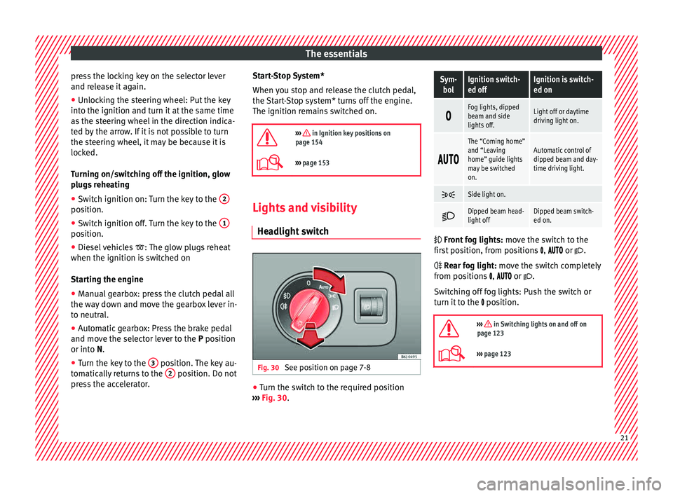
switch Fig. 30
See position on page 7-8 ●
Turn the switch to the required position
› ›
›
Fig. 30.
Sym-
bolIgnition switch-
ed offIgnition is switch-
ed on
Fog lights, dipped
beam and side
lights off.Light off or daytime
driving light on.
The “Coming home”
and “Leaving
home” guide lights
may be switched
on.Automatic control of
dipped beam and day-
time driving light.
Side light on.
Dipped beam head-
light offDipped beam switch-
ed on.
Front
fog lights: mo
ve the switch to the
first position, from positions , or .
Rear fog light: move the switch completely
from positions , or .
Switching off fog lights: Push the switch or
turn it to the position.
››› in Switching lights on and off on
page 123
››› page 123 21
Page 25 of 248
The essentials
Windscreen wipers and window wiper
b l
a
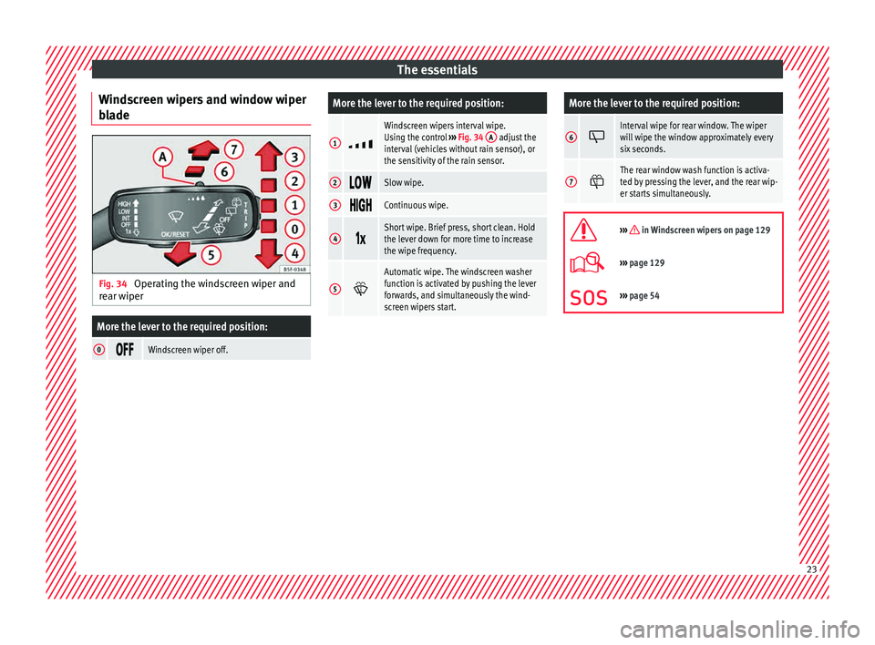
de Fig. 34
Operating the windscreen wiper and
r e
ar w
iper
More the lever to the required position:
0 Windscreen wiper off.
More the lever to the required position:
1
Windscreen wipers interval wipe.
Using the control
››› Fig. 34 A adjust the
interval (vehicles without rain sensor), or
the sensitivity of the rain sensor.
2 Slow wipe.
3
Continuous wipe.
4
Short wipe. Brief press, short clean. Hold
the lever down for more time to increase
the wipe frequency.
5
Automatic wipe. The windscreen washer
function is activated by pushing the lever
forwards, and simultaneously the wind-
screen wipers start.
More the lever to the required position:
6 Interval wipe for rear window. The wiper
will wipe the window approximately every
six seconds.
7
The rear window wash function is activa-
ted by pressing the lever, and the rear wip-
er starts simultaneously.
››› in Windscreen wipers on page 129
›››
page 129
››› page 54 23
Page 27 of 248
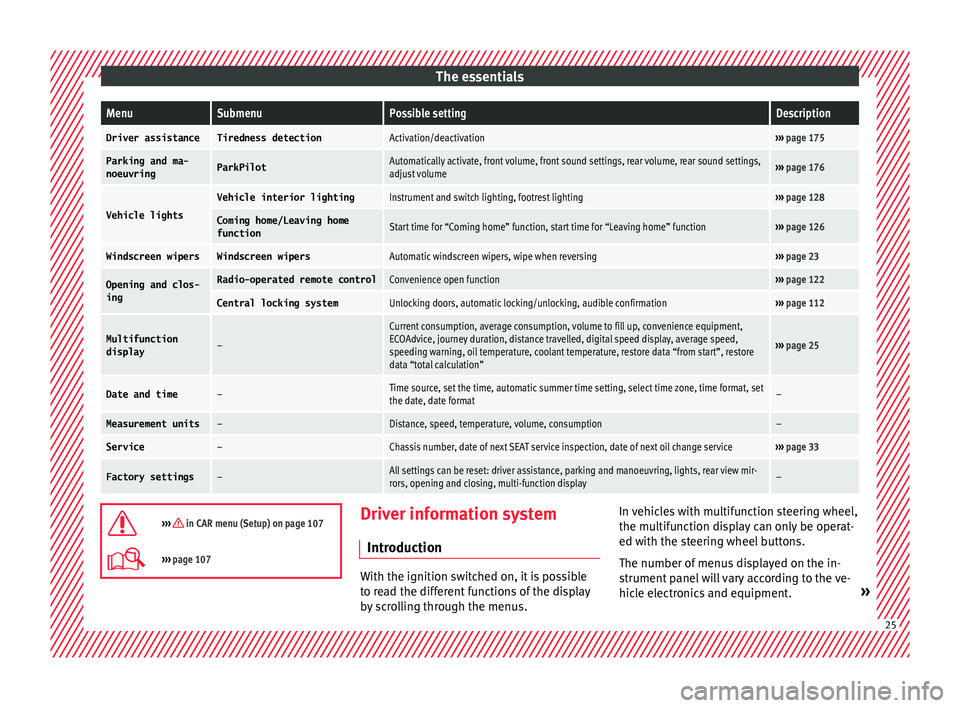
The essentialsMenuSubmenuPossible settingDescription
Driver assistanceTiredness detectionActivation/deactivation›››
page 175
Parking and ma-
noeuvringParkPilotAutomatically activate, front volume, front sound settings, rear volume, rear sound settings,
adjust volume››› page 176
Vehicle lights
Vehicle interior lightingInstrument and switch lighting, footrest lighting››› page 128
Coming home/Leaving home
functionStart time for “Coming home” function, start time for “Leaving home” function››› page 126
Windscreen wipersWindscreen wipersAutomatic windscreen wipers, wipe when reversing››› page 23
Opening and clos-
ingRadio-operated remote controlConvenience open function››› page 122
Central locking systemUnlocking doors, automatic locking/unlocking, audible confirmation››› page 112
Multifunction
display–
Current consumption, average consumption, volume to fill up, convenience equipment,
ECOAdvice, journey duration, distance travelled, digital speed display, average speed,
speeding warning, oil temperature, coolant temperature, restore data “from start”, restore
data “total calculation”
››› page 25
Date and time–Time source, set the time, automatic summer time setting, select time zone, time format, set
the date, date format–
Measurement units–Distance, speed, temperature, volume, consumption–
Service–Chassis number, date of next SEAT service inspection, date of next oil change service››› page 33
Factory settings–All settings can be reset: driver assistance, parking and manoeuvring, lights, rear view mir-
rors, opening and closing, multi-function display–
››› in CAR menu (Setup) on page 107
›››
page 107 Driver information system
Intr oduction With the ignition switched on, it is possible
to r
e
ad the different functions of the display
by scrolling through the menus. In vehicles with multifunction steering wheel,
the multif
u
nction display can only be operat-
ed with the steering wheel buttons.
The number of menus displayed on the in-
strument panel will vary according to the ve-
hicle electronics and equipment. » 25
Page 30 of 248
The essentials
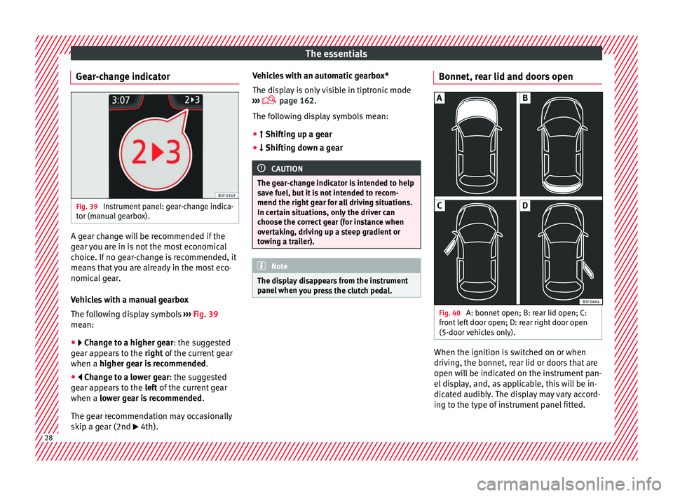
Gear-change indicator Fig. 39
Instrument panel: gear-change indica-
t or (m
anual
gearbox). A gear change will be recommended if the
g
e
ar
you are in is not the most economical
choice. If no gear-change is recommended, it
means that you are already in the most eco-
nomical gear.
Vehicles with a manual gearbox
The following display symbols ››› Fig. 39
mean:
● Chan ge to a higher gear: the suggested
g
ear appears to the right of the current gear
when a higher gear is recommended .
● Change to a lower gear: the suggested
g
ear appears to the left of the current gear
when a lower gear is recommended .
The gear recommendation may occasionally
skip a gear (2nd 4th). Vehicles with an automatic gearbox*
The dis
p
lay is only visible in tiptronic mode
››› page 162.
The following display symbols mean:
● Shiftin g up a gear
●
Shifting down a gear CAUTION
The gear-change indicator is intended to help
sav e f
uel, but it is not intended to recom-
mend the right gear for all driving situations.
In certain situations, only the driver can
choose the correct gear (for instance when
overtaking, driving up a steep gradient or
towing a trailer). Note
The display disappears from the instrument
panel when
you press the clutch pedal. Bonnet, rear lid and doors open
Fig. 40
A: bonnet open; B: rear lid open; C:
fr ont
l
eft door open; D: rear right door open
(5-door vehicles only). When the ignition is switched on or when
driv
in
g, the bonnet, r
ear lid or doors that are
open will be indicated on the instrument pan-
el display, and, as applicable, this will be in-
dicated audibly. The display may vary accord-
ing to the type of instrument panel fitted. 28
Page 31 of 248
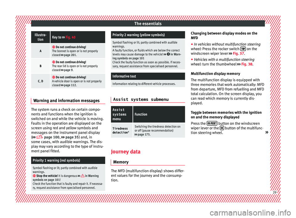
The essentialsIllustra-
tionKey to ››› Fig. 40
A Do not continue driving!
The bonnet is open or is not properly
closed ››› page 201.
B Do not continue driving!
The rear lid is open or is not properly
closed ››› page 9.
C, D Do not continue driving!
A vehicle door is open or is not properly
closed ››› page 112. Warning and information messages
The system runs a check on certain compo-
nents
and f
u
nctions when the ignition is
switched on and while the vehicle is moving.
Faults in the operation are displayed on the
screen using red and yellow symbols and
messages on the instrument panel display
( ›››
page 100,
››› page 35) and, in
some cases, with audible warnings. The dis-
play may vary according to the type of instru-
ment panel fitted.
Priority 1 warning (red symbols)
Symbol flashing or lit; partly combined with audible
warnings.
Stop the vehicle! It is dangerous ››› in Warning
symbols on page 101!
Check the function that is faulty and repair it. If necessa-
ry, request assistance from specialised personnel.
Priority 2 warning (yellow symbols)
Symbol flashing or lit; partly combined with audible
warnings.
A faulty function, or fluids which are below the correct
levels may cause damage to the vehicle! ›››
in Warn-
ing symbols on page 101
Check the faulty function as soon as possible. If neces-
sary, request assistance from specialised personnel.
Informative text
Information relating to different vehicle processes. Assist systems submenu
Assist
systems
menuFunction
Tiredness
detection *Switching the tiredness detection on
or off (pause recommendation)
››› page 175. Journey data
M emor y The MFD (multifunction display) shows differ-
ent
v
alues for the journey and the consump-
tion. Changing between display modes on the
MFD
● In vehicles without multifunction steering
wheel:
Press the rocker switch on the
w ind
s
creen wiper lever ››› Fig. 37.
● Vehicles with a multifunction steering
wheel:
turn the thumbwheel ››› Fig. 38.
Multifunction display memory
The multifunction display is equipped with
three memories that work automatically: MFD
from departure, MFD from refuelling and MFD
total calculation. On the screen display, you
can read which memory is currently dis-
played.
Toggle between memories with the ignition
on and the memory displayed
Press the button on the windscreen
w iper l
ev
er or the button of the multifunc-
tion s t
eerin
g wheel. » 29
Page 38 of 248
The essentials
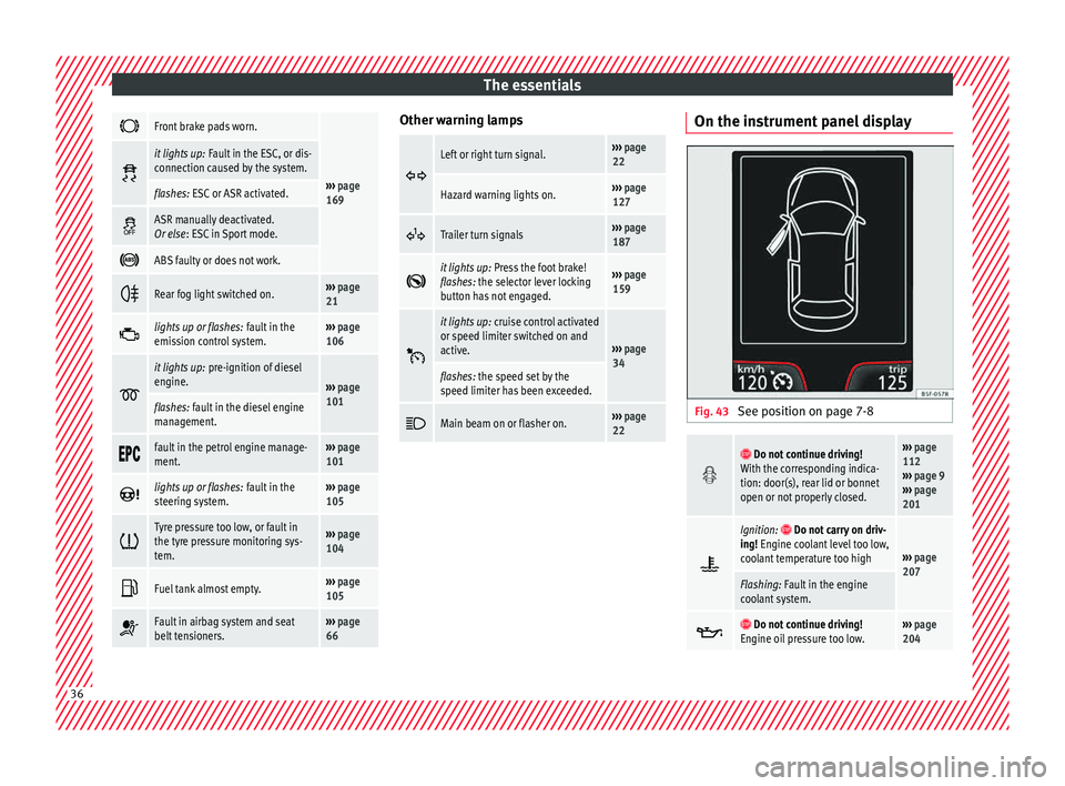
Front brake pads worn.
›››
page
169
it lights up:
Fault in the ESC, or dis-
connection caused by the system.
flashes: ESC or ASR activated.
ASR manually deactivated.
Or else
: ESC in Sport mode.
ABS faulty or does not work.
Rear fog light switched on.›››
page
21
lights up or flashes:
fault in the
emission control system.››› page
106
it lights up:
pre-ignition of diesel
engine.
››› page
101
flashes: fault in the diesel engine
management.
fault in the petrol engine manage-
ment.›››
page
101
lights up or flashes:
fault in the
steering system.››› page
105
Tyre pressure too low, or fault in
the tyre pressure monitoring sys-
tem.›››
page
104
Fuel tank almost empty.›››
page
105
Fault in airbag system and seat
belt tensioners.›››
page
66 Other warning lamps
Left or right turn signal.›››
page
22
Hazard warning lights on.››› page
127
Trailer turn signals›››
page
187
it lights up:
Press the foot brake!
flashes: the selector lever locking
button has not engaged.››› page
159
it lights up:
cruise control activated
or speed limiter switched on and
active.
››› page
34
flashes: the speed set by the
speed limiter has been exceeded.
Main beam on or flasher on.›››
page
22 On the instrument panel display
Fig. 43
See position on page 7-8
Do not continue driving!
With the corresponding indica-
tion: door(s), rear lid or bonnet
open or not properly closed.››› page
112
››› page 9
››› page
201
Ignition: Do not carry on driv-
ing! Engine coolant level too low,
coolant temperature too high
››› page
207
Flashing: Fault in the engine
coolant system.
Do not continue driving!
Engine oil pressure too low.››› page
204 36
Page 40 of 248
The essentials
● Rel
e
ase the clutch.
››› in Driving with manual gearbox on
page 159
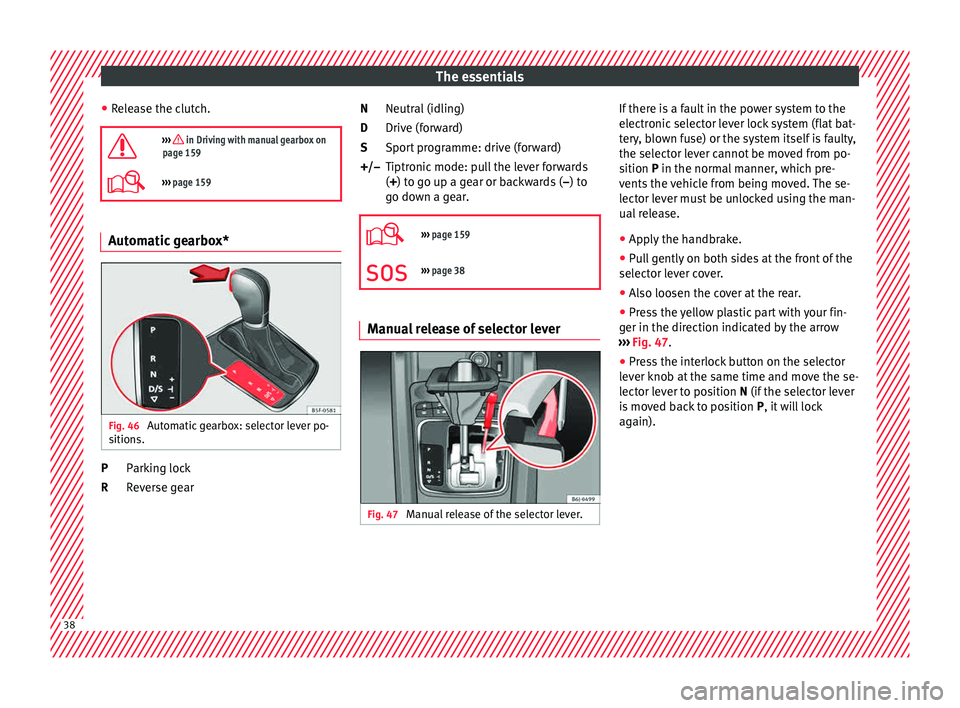
››› page 159 Automatic gearbox*
Fig. 46
Automatic gearbox: selector lever po-
s ition
s. Parking lock
R
ev
er
se gear
P
R Neutral (idling)
Drive (for
ward)
Sport programme: drive (forward)
Tiptronic mode: pull the lever forwards
(+) to go up a gear or backwards ( –) to
go down a gear.
››› page 159
››› page 38 Manual release of selector lever
Fig. 47
Manual release of the selector lever. N
D
S
+/–
If there is a fault in the power system to the
el
ectr
onic
selector lever lock system (flat bat-
tery, blown fuse) or the system itself is faulty,
the selector lever cannot be moved from po-
sition P in the normal manner, which pre-
vents the vehicle from being moved. The se-
lector lever must be unlocked using the man-
ual release.
● Apply the handbrake.
● Pull gently on both sides at the front of the
selector l
ever cover.
● Also loosen the cover at the rear.
● Press the yellow plastic part with your fin-
ger in the direction indic
ated by the arrow
››› Fig. 47.
● Press the interlock button on the selector
lever kno
b at the same time and move the se-
lector lever to position N (if the selector lever
is moved back to position P, it will lock
again). 38
Page 53 of 248
The essentials
Emergency towing of the vehi-
c l
e
T
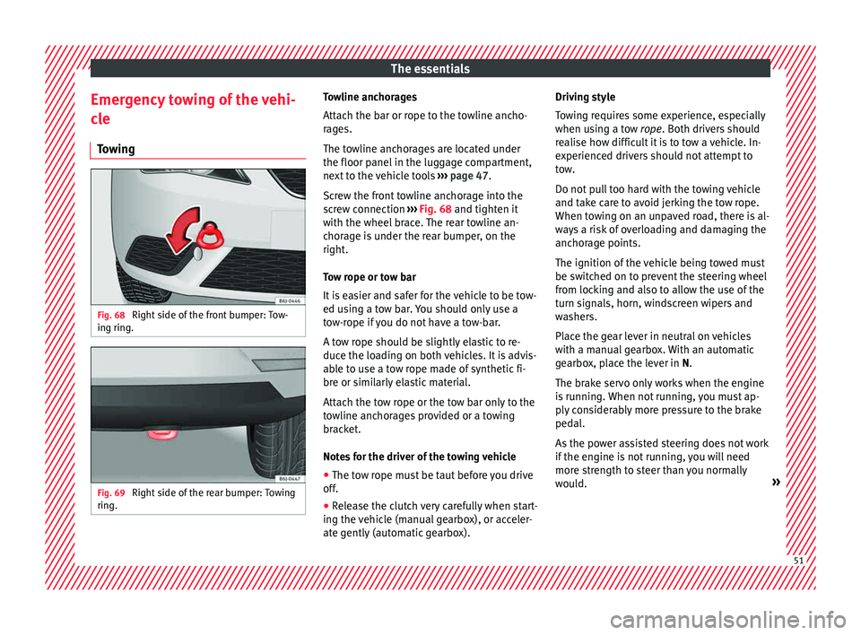
owing Fig. 68
Right side of the front bumper: Tow-
in g rin
g. Fig. 69
Right side of the rear bumper: Towing
rin g. Towline anchorages
Att
ac
h the b
ar or rope to the towline ancho-
rages.
The towline anchorages are located under
the floor panel in the luggage compartment,
next to the vehicle tools ››› page 47.
Screw the front towline anchorage into the
screw connection ››› Fig. 68 and tighten it
with the wheel brace. The rear towline an-
chorage is under the rear bumper, on the
right.
Tow rope or tow bar
It is easier and safer for the vehicle to be tow-
ed using a tow bar. You should only use a
tow-rope if you do not have a tow-bar.
A tow rope should be slightly elastic to re-
duce the loading on both vehicles. It is advis-
able to use a tow rope made of synthetic fi-
bre or similarly elastic material.
Attach the tow rope or the tow bar only to the
towline anchorages provided or a towing
bracket.
Notes for the driver of the towing vehicle
● The tow rope must be taut before you drive
off.
● Rel
ease the clutch very carefully when start-
ing the v
ehicle (manual gearbox), or acceler-
ate gently (automatic gearbox). Driving style
Tow
ing requires some experience, especially
when using a tow rope. Both drivers should
realise how difficult it is to tow a vehicle. In-
experienced drivers should not attempt to
tow.
Do not pull too hard with the towing vehicle
and take care to avoid jerking the tow rope.
When towing on an unpaved road, there is al-
ways a risk of overloading and damaging the
anchorage points.
The ignition of the vehicle being towed must
be switched on to prevent the steering wheel
from locking and also to allow the use of the
turn signals, horn, windscreen wipers and
washers.
Place the gear lever in neutral on vehicles
with a manual gearbox. With an automatic
gearbox, place the lever in N.
The brake servo only works when the engine
is running. When not running, you must ap-
ply considerably more pressure to the brake
pedal.
As the power assisted steering does not work
if the engine is not running, you will need
more strength to steer than you normally
would. » 51