light Seat Toledo 2014 Manual PDF
[x] Cancel search | Manufacturer: SEAT, Model Year: 2014, Model line: Toledo, Model: Seat Toledo 2014Pages: 200, PDF Size: 4.37 MB
Page 145 of 200

Checking and refilling levels
CAUTION
In vehicles fitted with the “Start-Stop” sys-
tem, the charger cable cannot be directly con-
nected to the negative terminal of the vehicle
battery but must be attached to the engine
ground point ››› page 158. Disconnecting and connecting the
battery
The following functions will either be inoper-
ative or will not work properly after discon-
necting and reconnecting the battery:FunctionInstallation
Setting the clock›››
page 32
The multifunction display data
is deleted››› page 39 Note
We recommend having the vehicle checked by
an authorised SEAT dealer to guarantee the
correct working order of all electrical sys-
tems. Changing the battery
A replacement battery must have the same
capacity, voltage, current rating and size as
the original. The appropriate types of battery can be acquired from authorised SEAT deal-
ers.
We recommend having the battery changed
by an authorised SEAT dealer, where the new
battery will be correctly installed and the
original disposed of in line with regulations.
Automatic disconnection of electrical
equipment When heavily-charging a battery, the pro-
gramme selected by the electrical system
control unit prevents the battery from auto-
matically discharging. This may result in the
following:
● Increase in idling speed so that the alterna-
tor can supply more current to the electrical
system.
● The performance of certain electrical com-
ponents could be limited or some may switch
off temporarily, e.g. the heated seats, the
heated rear window, the 12 V power socket. Note
Despite any measures taken by the control
unit, the battery could drain. e.g. with the en-
gine is switched off, the key is turned in the
ignition for a long period or the side lights or
parking lights are switched on. The switching
off of certain electrical components does not
impair driving comfort and often the driver
will not even notice. 143
Technical specifications
Advice
Operation
Safety
Page 149 of 200

Wheels and tyres
The tyre pressure of the spare wheel must be
checked (preferably whenever the tyre pres-
sure is checked – see sticker on fuel tank flap
››› page 144 ) to ensure the spare wheel re-
m ain
s ready for use.
If the spare wheel is not the same size or de-
sign as the tyres that are mounted on the car
(for example if the car has winter tyres or
tyres with direction tread), only use the spare
tyre for a short period of time in the event of
breakdown and drive with the corresponding
care ››› .
It must be replaced as soon as possible for a
wheel with a normal size and finish.
Temporary spare wheel
If the vehicle is equipped with a temporary
spare wheel, there will be a warning sign on
the rim of the wheel.
Follow the instructions below when driving
with this wheel fitted.
● After fitting the wheel, the warning sign
must not be covered.
● Do not drive faster than 80 km/h (50 mph)
with the spare wheel and take great care
while driving. Avoid heavy acceleration, hard
braking and fast cornering.
● The tyre pressure is the same as that of the
standard tyres. ●
Only use this spare wheel to reach the
nearest Official Service, as it is not designed
for permanent use. WARNING
● Under no circumstances must damaged
spare wheels be used.
● If the spare wheel is different in size or de-
sign to the tyres currently fitted, never drive
faster than 80 km/h (50 mph). Avoid heavy
acceleration, hard braking and fast cornering. CAUTION
Follow the instructions given on the tempora-
ry spare wheel label. Note
The tyre pressure of the spare wheel must al-
ways correspond to the highest pressure pre-
scribed for the model of vehicle in question. Tyre control systems
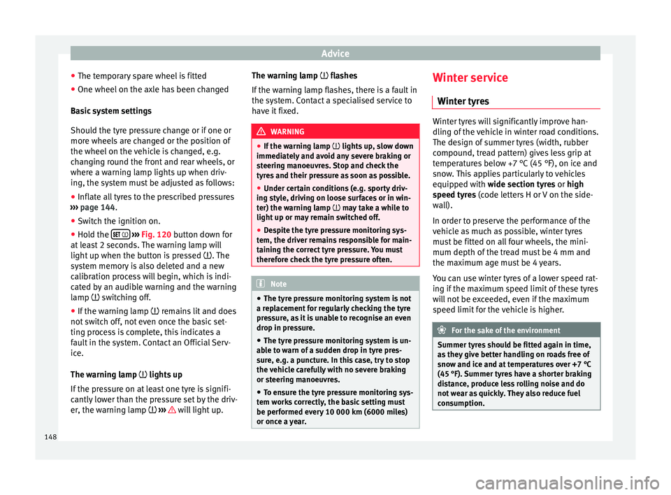
Tyre pressure* Fig. 120
Tyre pressure adjustment switch. The tyre pressure monitoring system uses
ABS sensors to compare the revolutions and
the circumference of each wheel. Should the
circumference of any wheel change, the
warning lamp on the general dash panel
››› page 38 will light up and an audible warn-
in g w
ill be heard.
Tyre circumference may change if:
● Tyre pressure is too low
● Tyre structure is damaged
● Vehicle load not evenly distributed
● wheels on one axle are subjected to greater
load, (e.g. driving with trailer, uphill, down-
hill);
● Snow chains are fitted »
147
Technical specifications
Advice
Operation
Safety
Page 150 of 200
Advice
● The temporary spare wheel is fitted
● One wheel on the axle has been changed
Basic system settings
Should the tyre pressure change or if one or
more wheels are changed or the position of
the wheel on the vehicle is changed, e.g.
changing round the front and rear wheels, or
where a warning lamp lights up when driv-
ing, the system must be adjusted as follows:
● Inflate all tyres to the prescribed pressures
››› page 144 .
● Sw it
ch the ignition on.
● Hold the
››› Fig. 120 button down for
at least 2 seconds. The warning lamp will
light up when the button is pressed . The
system memory is also deleted and a new
calibration process will begin, which is indi-
cated by an audible warning and the warning
lamp switching off.
● If the warning lamp remains lit and does
not switch off, not even once the basic set-
ting process is complete, this indicates a
fault in the system. Contact an Official Serv-
ice.
The warning lamp lights up
If the pressure on at least one tyre is signifi-
cantly lower than the pressure set by the driv-
er, the warning lamp ››› will light up.The warning lamp flashes
If the warning lamp flashes, there is a fault in
the system. Contact a specialised service to
have it fixed.
WARNING
● If the warning lamp lights up, slow down
immediately and avoid any severe braking or
steering manoeuvres. Stop and check the
tyres and their pressure as soon as possible.
● Under certain conditions (e.g. sporty driv-
ing style, driving on loose surfaces or in win-
ter) the warning lamp may take a while to
light up or m
ay remain switched off.
● Despite the tyre pressure monitoring sys-
tem, the driver remains responsible for main-
taining the correct tyre pressure. You must
therefore check the tyre pressure often. Note
● The tyre pressure monitoring system is not
a replacement for regularly checking the tyre
pressure, as it is unable to recognise an even
drop in pressure.
● The tyre pressure monitoring system is un-
able to warn of a sudden drop in tyre pres-
sure, e.g. a puncture. In this case, try to stop
the vehicle carefully with no severe braking
or steering manoeuvres.
● To ensure the tyre pressure monitoring sys-
tem works correctly, the basic setting must
be performed every 10 000 km (6000 miles)
or once a year. Winter service
Winter tyres Winter tyres will significantly improve han-
dling of the vehicle in winter road conditions.
The design of summer tyres (width, rubber
compound, tread pattern) gives less grip at
temperatures below +7 °C (45 °F), on ice and
snow. This applies particularly to vehicles
equipped with wide section tyres or high
s
peed ty
res (code letters H or V on the side-
wall).
In order to preserve the performance of the
vehicle as much as possible, winter tyres
must be fitted on all four wheels, the mini-
mum depth of the tread must be 4 mm and
the maximum age must be 4 years.
You can use winter tyres of a lower speed rat-
ing if the maximum speed limit of these tyres
will not be exceeded, even if the maximum
speed limit for the vehicle is higher. For the sake of the environment
Summer tyres should be fitted again in time,
as they give better handling on roads free of
snow and ice and at temperatures over +7 °C
(45 °F). Summer tyres have a shorter braking
distance, produce less rolling noise and do
not wear as quickly. They also reduce fuel
consumption. 148
Page 152 of 200
Advice
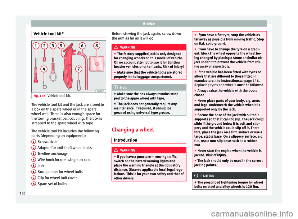
Vehicle tool kit* Fig. 122
Vehicle tool kit. The vehicle tool kit and the jack are stored in
a box on the spare wheel or in the spare
wheel well. There is also enough space for
the towing bracket ball coupling. The box is
strapped to the spare wheel with tape.
The vehicle tool kit includes the following
parts (depending on equipment):
Screwdriver
Adapter for anti-theft wheel bolts
Towline anchorage
Wire hook for removing hub caps
Jack
Box spanner for wheel bolts
Clip for wheel bolt cover
Spare set of bulbs
1 2
3
4
5
6
7
8 Before stowing the jack again, screw down
the arm as far as it will go.
WARNING
● The factory-supplied jack is only designed
for changing wheels on this model of vehicle.
On no account attempt to use it for lighting
heavier vehicles or other loads. Risk of injury!
● Make sure that the vehicle tools are stored
properly in the luggage compartment. Note
● Make sure the box always remains strap-
ped to the spare wheel with tape.
● The jack does not generally require any
maintenance. If required, it should be
greased using universal type grease. Changing a wheel
Introduction WARNING
● If you have a puncture in moving traffic,
switch on the hazard warning lights and
place the warning triangle at the obligatory
distance. Observe applicable local legal regu-
lations. This is for your own safety and that of
other drivers. ●
If you have a flat tyre, stop the vehicle as
far away as possible from moving traffic. Stop
on flat, solid ground.
● If you have to change the tyre on a gradi-
ent, block the wheel opposite the wheel be-
ing changed by placing a stone or similar ob-
ject under it to prevent the vehicle from roll-
ing away unexpectedly.
● If the vehicle has been fitted with tyres or
alloys that are different to those fitted in
manufacture, the instructions ››› page 146,
Replacing tyres and wheels must be followed.
● Always raise the vehicle with the doors
closed.
● Never place parts of your body, e.g. arms
and legs, underneath the vehicle when it is
supported only by the jack.
● Secure the base of the jack with suitable
supports so that it cannot slip. The jack could
slide if the ground below it is soft and slip-
pery and the vehicle could slip off it. There-
fore, place the jack on a firm surface or use a
large, stable base. On a slippery surface, e.g.
tile, use a non-slip base such as a rubber
mat.
● Never start the engine when the vehicle is
jacked. Risk of injury.
● The jack should only be used in the correct
jacking points. CAUTION
● The prescribed tightening torque for wheel
bolts on steel and alloy wheels is 120 Nm. 150
Page 154 of 200
Advice
Wheel bolts The wheel bolts
are m atched to the rims.
When installing different wheels, e.g. to fit
light alloy wheels or wheels with winter tyres,
it is important to use the correct wheel bolts
with the right length and correctly shaped
bolt heads. This is essential for a secure fit of
the wheels and for proper operation of the
brake system.
Changing a wheel If possible, change the wheel on a level sur-
face.
– Pull off the hub cap ›››
page 151 or the
wheel bolt covers ›››
page 151.
– First loosen the anti-theft wheel bolts and
then the other wheel bolts ›››
page 152.
– Raise the vehicle until the wheel to be
changed is no longer touching the ground
››› page 153 .
– Remo
ve the wheel bolts and place them on
a clean surface (cloth, paper, etc.).
– Take off the wheel.
– Lift the spare wheel into position and tight-
en the wheel bolts lightly.
– Lower the vehicle. –
Tighten the wheel bolts firmly in diagonal
sequence with the box spanner and then
the anti-theft wheel bolt ››› page 152.
– Replace the hub cap and/or the bolt cov-
ers. Note
● All bolts must be clean and turn easily.
● Never grease or oil the wheel bolts!
● Note the direction of rotation when putting
on a tyre with a directional tread pattern
››› page 144. After changing a wheel
Tasks that must be carried out after changing
a wheel:
– Place the wheel with the defective tyre in
the spare wheel well and secure it using a
special bolt ›››
page 146 .
– Put
the vehicle tools back in their storage
location.
– Check the tyre pressure of the newly fitted
s
pare wheel as soon as possible.
– Have the tightening torque of the wheel
bo
lts checked as soon as possible with a
torque wrench.
– Have the flat tyre replaced or ask an Official
Service about the possibility of repair. Note
● If you notice that the wheel bolts are rusty
and difficult to turn when changing a wheel,
they must be replaced before having the
tightening torque checked.
● Drive carefully and at moderate speeds un-
til the tightening torque of the wheel bolts
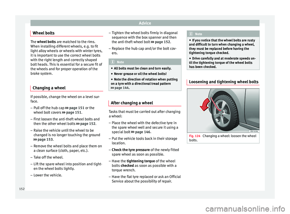
has been checked. Loosening and tightening wheel bolts
Fig. 124
Changing a wheel: loosen the wheel
bolts. 152
Page 155 of 200
Emergencies
Loosening wheel bolts – Fit the box spanner as far as it will go over
the wheel bolt 1)
.
– Grip the end of the box spanner and turn
the wheel bolt about one turn anti-clock-
w i
se ››› Fig. 124.
Tightening wheel bolts – Fit the box spanner as far as it will go over
the wheel bolt 1)
.
– Grip the box spanner as close to the end as
possible and tighten the bolt firmly by turn-
ing clockwise. WARNING
The wheel bolts should only be loosened
slightly (about one turn) before raising the
vehicle with the jack. Risk of accident! Note
If the wheel bolt is very tight, it may be pos-
sible to loosen it by pushing down the end of
the box spanner carefully with your foot. Hold
on to the vehicle for support and take care
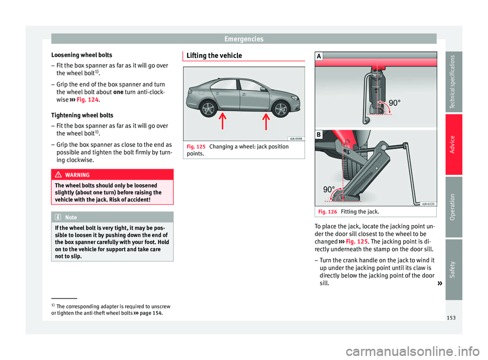
not to slip. Lifting the vehicle
Fig. 125
Changing a wheel: jack position
points. Fig. 126
Fitting the jack. To place the jack, locate the jacking point un-
der the door sill closest to the wheel to be
changed
››› Fig. 125 . The jacking point is di-
r ectly
underneath the stamp on the door sill.
– Turn the crank handle on the jack to wind it
up under the jacking point until its claw is
directly below the jacking point of the door
sill.
»1)
The corresponding adapter is required to unscrew
or tighten the anti-theft wheel bolts ››› page 154.
153
Technical specifications
Advice
Operation
Safety
Page 159 of 200

Emergencies
Check after 10 minutes of driving Check the tyre pressure after 10 minutes of
driving!
If the tyre pressure is less than 1.3 bar
(18.8 psi/130 kPa):
– Do not drive on! The tyr e cannot be suffi-
ciently filled using the tyre repair kit.
– See professional assistance.
If the tyre pressure is greater than 1.3 bar
(18.8 psi/130 kPa): – Correct the tyre pressure again to the cor-
rect value (see inside of the fuel tank flap).
– Carefully drive to the nearest specialised
workshop at a maximum speed of 80 km/h
(50 mph).
Jump-starting Introduction If the engine fails to start because of a dis-
charged battery, the battery can be connec-
ted to the battery of another vehicle to start
the engine. Suitable jump leads are required.
Both batteries need to have nominal voltage
of 12 V. The
capacity (Ah) of the back-up bat- t
er
y should not be notably less than the
drained battery.
Jump leads
The jump leads must be heavy enough to car-
ry the starter current and must be fitted with
insulated battery clamps. Refer to the instruc-
tions given by the manufacturer.
Positive cable – usually red
Neg
ative cable
– usually black WARNING
● A flat battery can also freeze at tempera-
tures slightly below to 0 °C (32 °F). Do not at-
tempt to start the vehicle with a frozen bat-
tery. Risk of explosion!
● Please note the safety warnings referring to
working in the engine compartment
››› page 132.
● The non-in s
ulated parts of the battery
clamps must not be allowed to touch. Addi-
tionally, the jump lead attached to the posi-
tive battery terminal must not touch metal
parts of the vehicle. Risk of short circuit!
● Do not connect the negative lead to the
negative terminal of the discharged battery.
In the event of sparks when starting the en-
gine, the explosive gas given off by the bat-
tery could catch fire.
● Position the jump leads in such a way that
they cannot come into contact with any mov-
ing parts in the engine compartment. ●
Do not bend over the battery. Risk of acid
burns!
● The screw plugs on the battery cells must
be screwed in firmly.
● Keep sources of fire (flames, lit cigarettes,
etc.) away from the battery. - Risk of explo-
sion!
● Never use the jump leads on batteries in
which the electrolyte level is too low. Risk of
explosion and acid burns. Note
● The vehicles must not touch each other, as
electricity could flow as soon as the positive
terminals are connected.
● The discharged battery must be properly
connected to the vehicle electrical system.
● The jump leads should be checked in a spe-
cialist vehicle battery shop. 157
Technical specifications
Advice
Operation
Safety
Page 160 of 200

Advice
How to jump start: description Fig. 129
Diagram of connections for vehicles
without Start Stop system Fig. 130
Diagram of connections for vehicles
with Start Stop system Jump lead terminal connections
1. Switch off the ignition of both vehicles
››› . 2. Connect one end of the
red jump lead to
the po s
itive + terminal of the vehicle
with the flat battery A
››› Fig. 129 .
3. C
onnect the other end of the red
jump
lead to the positive terminal + in the ve-
hicle providing assistance B .
4. For vehicles without Start-Stop system:
connect one end of the black jump lead to
the negative terminal – of the vehicle
providing the current B
››› Fig. 129 .
– For
vehicles with Start-Stop system: con-
nect one end of the black jump lead X to a
suitable ground terminal, to a solid piece of
metal in the engine block, or to the engine
block itself ››› Fig. 130 .
5. C
onnect the other end of the black jump
lead X to a solid metal component bolted
to the engine block or to the engine block
itself of the vehicle with the flat battery.
Do not connect it to a point near the bat-
tery A .
6. Position the leads in such a way that they cannot come into contact with any moving
parts in the engine compartment.
Starting
7. Start the engine of the vehicle with the boosting battery and let it run at idling
speed. 8. Start the engine of the vehicle with the flat
battery and wait 2 or 3 minutes until the
engine is “running”.
Removing the jump leads
9. Before you remove the jump leads, switch off the dipped beam headlights (if they
are switched on).
10.Turn on the heater blower and heated rear window in the vehicle with the flat battery.
This helps minimise voltage peaks which
are generated when the leads are discon-
nected.
11. When the engine is running, disconnect
the l e
ads in reverse order to the details
given above.
Connect the battery clamps so they have
good metal-to-metal contact with the battery
terminals.
If the engine fails to start, switch off the start-
er after about 10 seconds and try again after
about 1 minute. WARNING
● Please note the safety warnings referring to
working in the engine compartment
››› page 132.
● The b att
ery providing assistance must have
the same voltage as the flat battery (12V) and
approximately the same capacity (see imprint 158
Page 161 of 200

Emergencies
on battery). Failure to comply could result in
an explosion.
●
Never use jump leads when one of the bat-
teries is frozen. Danger of explosion! Even af-
ter the battery has thawed, battery acid could
leak and cause chemical burns. If a battery
freezes, it should be replaced.
● Keep sparks, flames and lighted cigarettes
away from batteries, danger of explosion.
Failure to comply could result in an explo-
sion.
● Observe the instructions provided by the
manufacturer of the jump leads.
● Do not connect the negative cable from the
other vehicle directly to the negative terminal
of the flat battery. The gas emitted from the
battery could be ignited by sparks. Danger of
explosion.
● Do not attach the negative cable from the
other vehicle to parts of the fuel system or to
the brake line.
● The non-insulated parts of the battery
clamps must not be allowed to touch. The
jump lead attached to the positive battery
terminal must not touch metal parts of the ve-
hicle, this can cause a short circuit.
● Position the leads in such a way that they
cannot come into contact with any moving
parts in the engine compartment.
● Do not lean on the batteries. This could re-
sult in chemical burns. Note
The vehicles must not touch each other, oth-
erwise electricity could flow as soon as the
positive terminals are connected. Towing the vehicle
Introduction Vehicles with manual gearbox can be towed
using a towbar or towrope. They can also be
towed with either the front or rear wheels lif-
ted off the road.
Vehicles with automatic gearbox can be tow-
ed using a towbar or towrope. They can also
be towed with the front wheels lifted off the
road. If the vehicle is towed with the rear
wheels lifted off the road the automatic gear-
box will be damaged!
It is safer to tow a vehicle with a
towbar. A
towrope should only be used if you do not
h av
e a towbar.
Follow the instructions below when towing a
vehicle:
Notes for the driver of the towing vehicle
– Engage the clutch very gently when starting
to move or on vehicles with automatic gear-
box press the accelerator carefully. –
On vehicles with a manual gearbox, the
towrope must be taut before driving off.
Maximum towing speed is 50 km/h (31
mph).
Note
s for the driver of the towed vehicle
– The ignition should be switched on so that
the steering wheel lock is not engaged and
the turn signals, horn and windscreen wip-
ers and washers can be used.
– Put the gear lever in neutral or move the se-
lector lever to position N (automatic gear-
bo
x).
The brake servo and power steering only
work when the engine is running. Considera-
bly more effort is required on the brake pedal
and steering wheel when the engine is
switched off.
Ensure the towrope remains taut at all times
when towing. CAUTION
● Do not tow-start the engine. Risk of engine
damage! In vehicles with a catalytic convert-
er, fuel that has not been burned could reach
the catalytic converter and catch fire in it.
This could damage and destroy the catalytic
converter. You may use the battery from an-
other vehicle to help you start your engine
››› page 158.
» 159
Technical specifications
Advice
Operation
Safety
Page 162 of 200
Advice
●
If, due to a fault, there is no oil in the gear-
box, the car may only be towed with the
driven wheels lifted clear of the road and
transported on a special vehicle transporter
or trailer.
● If normal towing is not possible or if the ve-
hicle is to be towed for further than 50 km,
the vehicle must be transported on a special
vehicle transporter or trailer.
● The towrope should be slightly elastic to
reduce the load on both vehicles during tow-
ing. It is advisable to use a towrope made of
synthetic fibre or similar material only.
● Do not pull too hard with the towing vehicle
and always take care to avoid jerking the tow-
rope. When towing on a loose surface there is
always a risk of overloading and damaging
the anchorage points.
● Attach the towrope or towbar only to the
towline anchorages or to the removable tow-
ing bracket ››› page 114, or ››› page 161. Note
● We recommend you use the towrope or tow-
bar available in the SEAT Original Accessories
programme from authorised SEAT dealers.
● Towing a vehicle requires a certain degree
of practical skill. Both drivers should be fa-
miliar with the technique required for towing.
Inexperienced drivers should not attempt to
tow away another vehicle or to have their ve-
hicle towed. ●
Note the legal regulations concerning tow-
ing, particularly those regarding the signal-
ling of the towed and towing vehicle.
● The towrope must not be twisted, as under
certain circumstances this could unscrew the
front towline anchorage. Towline anchorage
Fig. 131
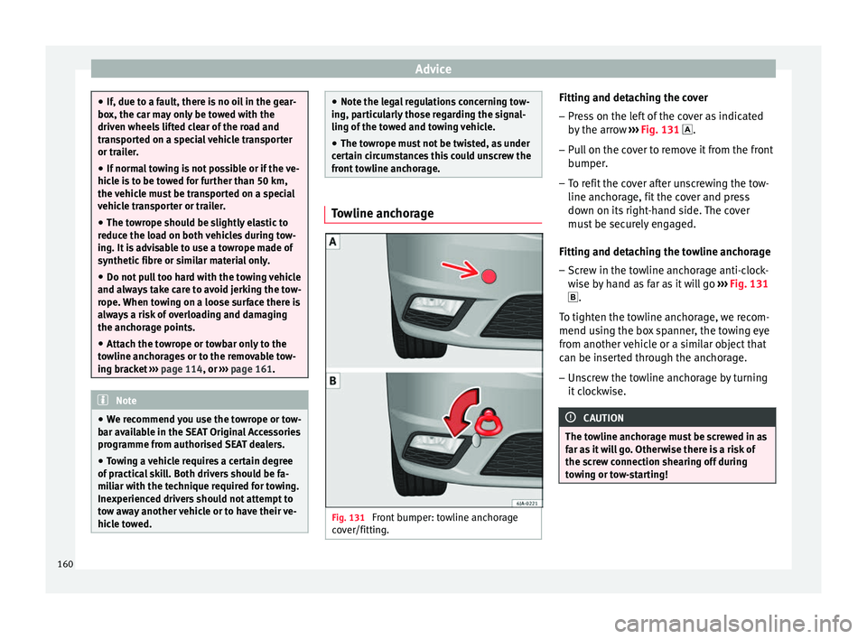
Front bumper: towline anchorage
cover/fitting. Fitting and detaching the cover
– Press on the left of the cover as indicated
by the arrow ››› Fig. 131 .
– Pull on the cover to remove it from the front
bumper.
– To refit the cover after unscrewing the tow-
line anchorage, fit the cover and press
down on its right-hand side. The cover
must be securely engaged.
Fitting and detaching the towline anchorage
– Screw in the towline anchorage anti-clock-
wise by hand as far as it will go ››› Fig. 131
.
To tighten the towline anchorage, we recom-
mend using the box spanner, the towing eye
from another vehicle or a similar object that
can be inserted through the anchorage.
– Unscrew the towline anchorage by turning
it clockwise. CAUTION
The towline anchorage must be screwed in as
far as it will go. Otherwise there is a risk of
the screw connection shearing off during
towing or tow-starting! 160