SKODA FABIA 2014 2.G / 5J Owner's Manual
Manufacturer: SKODA, Model Year: 2014, Model line: FABIA, Model: SKODA FABIA 2014 2.G / 5JPages: 197, PDF Size: 13.56 MB
Page 121 of 197
If after stopping the car, the message UNABLE TO START STOP appears in the
segment display or in the MAXI DOT display the check mark » Fig. 115 , then
the conditions for automatic engine shutdown are not met.
Running the engine is essential, for example, for the following reasons.
› The engine temperature for the proper function of the system has not yet
been reached.
› The charge state of the vehicle battery is too low.
› The current consumption is too high.
› High air-conditioning or heating capacity (high fan speed, big difference be-
tween the desired and actual indoor temperature).
Note
■ If the vehicle remains outdoors for a long time in minus temperatures or in
direct sunlight, it can take several hours until the internal temperature of the
vehicle battery reaches a suitable temperature for proper operation of the
START STOP system.■
If the driver's seat belt is removed for more than approx. 30 seconds or the
driver's door is opened during stop mode, the engine will have to be started
manually.
■
After manual engine start, the automatic engine shutdown can take place
only when a minimum distance required for the system function has been cov-
ered.
Operation
Read and observe
on page 118 first.
In compliance with the operating conditions, automatic engine shutdown / au-
tomatic engine start takes place as described.
Automatic engine shut down
›
Stop the vehicle.
›
Shift the gear lever to Neutral.
›
Release the clutch pedal.
Automatic engine shutdown takes place, segment display shows START STOP
ACTIVE or a check mark appears in the MAXI DOT display
» Fig. 115 on
page 118 .
Automatic engine start
›
Depress the clutch pedal.
The automatic start procedure takes place again.
System conditioned automatic start-up
Read and observe
on page 118 first.
When the engine is off, the system can automatically start the engine before
the desired journey continues. The possible reasons for this are, for example:
› The vehicle has begun to roll, e.g. on a slope.
› The brake pedal has been actuated several times.
› The current consumption is too high.
Manually deactivating/activating
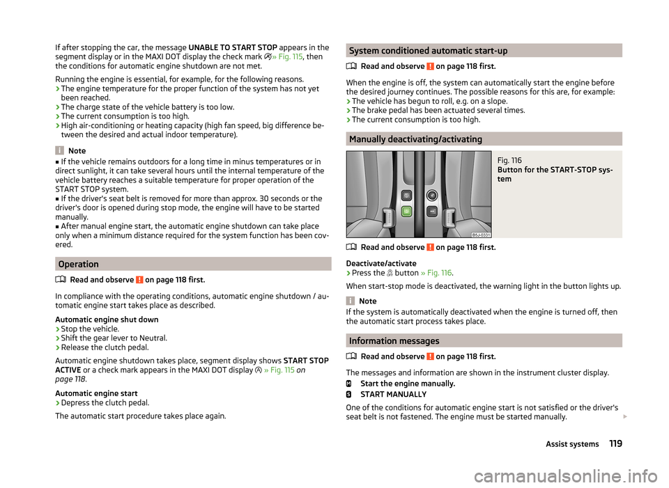
Fig. 116
Button for the START-STOP sys-
tem
Read and observe on page 118 first.
Deactivate/activate
›
Press the button
» Fig. 116 .
When start-stop mode is deactivated, the warning light in the button lights up.
Note
If the system is automatically deactivated when the engine is turned off, then
the automatic start process takes place.
Information messages
Read and observe
on page 118 first.
The messages and information are shown in the instrument cluster display. Start the engine manually.
START MANUALLY
One of the conditions for automatic engine start is not satisfied or the driver's
seat belt is not fastened. The engine must be started manually.
119Assist systems
Page 122 of 197
Error: start-stop system
ERROR START-STOP
A system error is present. Seek help from a specialist garage.Towing a trailer
Towing device
Introduction
This chapter contains information on the following subjects:
Description
121
Adjusting the ready position
121
Fitting the ball head
122
Check proper fitting
122
Removing the ball head
123
Use and care
123
If your vehicle has already been factory-fitted with towing equipment or is fit-
ted with towing equipment from ŠKODA Original Accessories, then it meets all
of the technical requirements and national legal provisions for towing a trailer.
Your vehicle is fitted with a 13-pin power socket for the electrical connection
between the vehicle and trailer. If the trailer that is to be towed has a 7-pin
connector , you can use a suitable adapter from ŠKODA Original Accessories.
The maximum trailer drawbar load is 50 kg.
WARNING■
Check that the ball head is seated correctly and is secured in the mount-
ing recess before starting any journey.■
Do not use the ball head if it is not correctly inserted in the mounting re-
cess.
■
Do not use the towing equipment if it is damaged or incomplete.
■
Do not modify or adapt the towing equipment in any way.
■
Never release the ball head while the trailer is still coupled.
CAUTION
Take care with the ball head to avoid damaging the paintwork on the bumper.120Driving
Page 123 of 197
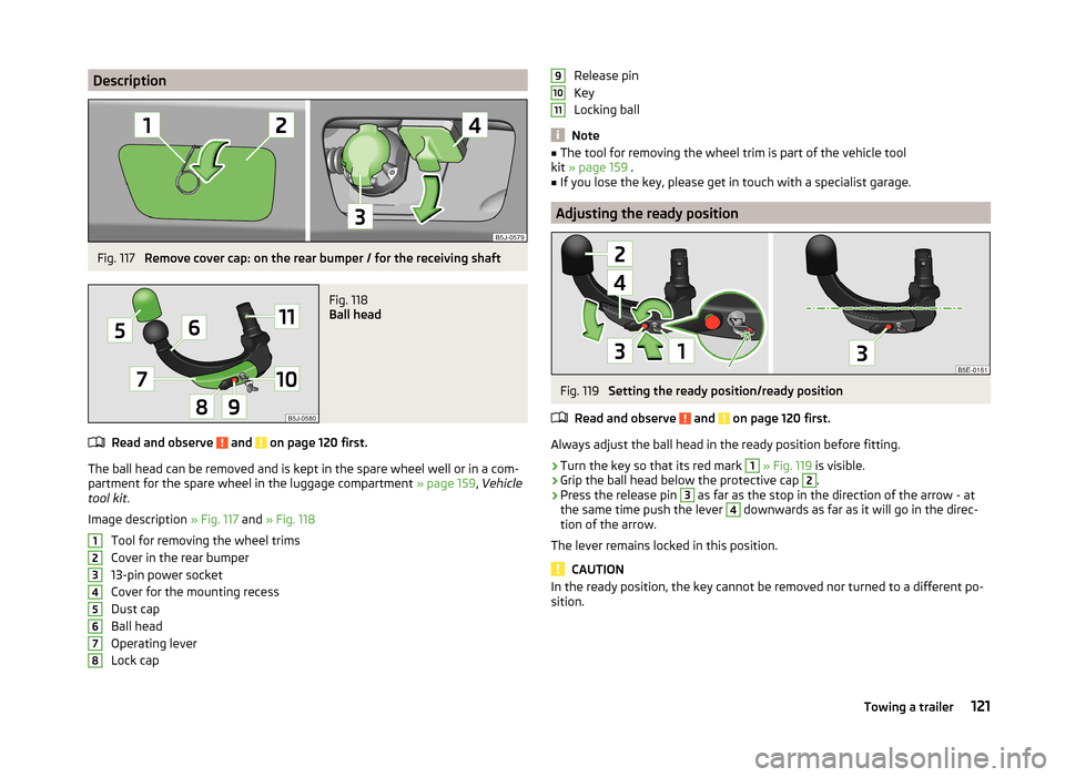
DescriptionFig. 117
Remove cover cap: on the rear bumper / for the receiving shaft
Fig. 118
Ball head
Read and observe and on page 120 first.
The ball head can be removed and is kept in the spare wheel well or in a com-
partment for the spare wheel in the luggage compartment » page 159, Vehicle
tool kit .
Image description » Fig. 117 and » Fig. 118
Tool for removing the wheel trims
Cover in the rear bumper
13-pin power socket
Cover for the mounting recess
Dust cap
Ball head
Operating lever
Lock cap
12345678Release pin
Key
Locking ball
Note
■ The tool for removing the wheel trim is part of the vehicle tool
kit » page 159 .■
If you lose the key, please get in touch with a specialist garage.
Adjusting the ready position
Fig. 119
Setting the ready position/ready position
Read and observe
and on page 120 first.
Always adjust the ball head in the ready position before fitting.
›
Turn the key so that its red mark
1
» Fig. 119 is visible.
›
Grip the ball head below the protective cap
2
.
›
Press the release pin
3
as far as the stop in the direction of the arrow - at
the same time push the lever
4
downwards as far as it will go in the direc-
tion of the arrow.
The lever remains locked in this position.
CAUTION
In the ready position, the key cannot be removed nor turned to a different po-
sition.91011121Towing a trailer
Page 124 of 197
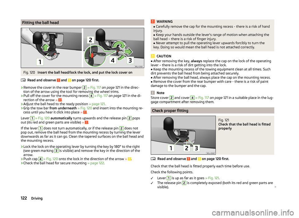
Fitting the ball headFig. 120
Insert the ball head/lock the lock, and put the lock cover on
Read and observe
and on page 120 first.
›
Remove the cover in the rear bumper
2
» Fig. 117 on page 121 in the direc-
tion of the arrow using the tool for removing the wheel trims.
›
Pull off the cover for the mounting recess
4
» Fig. 117 on page 121 in the di-
rection of the arrow » .
›
Adjust the ball head to the ready position » page 121.
›
Grip the tow bar from underneath » Fig. 120 and insert into the mounting re-
cess until you hear it click into place » .
Lever
1
» Fig. 120 automatically turns upwards and the release pin
2
pops
out (its red and green parts are visible) » .
If the lever
1
does not turn automatically, or if the release pin
2
does not
pop out, remove the ball head from the mounting recess by turning the lever
downwards as far as it can go. Clean the tapered surfaces on the ball head and
the mounting recess.
›
Lock the lock on the operating lever by turning the key by 180° to the right
(see green marking
3
is visible) and remove the key in the direction of the
arrow.
›
Push cap
4
» Fig. 120 onto the lock in the direction of the arrow » .
›
Check the ball head for secure mounting » page 122.
WARNING■
Carefully remove the cap for the mounting recess - there is a risk of hand
injury.■
Keep your hands outside the lever's range of motion when attaching the
ball head – there is a risk of finger injury.
■
Never attempt to pull the operating lever upwards forcibly to turn the
key. Doing so would mean the ball head is not attached correctly.
CAUTION
■ After removing the key, always replace the cap on the lock of the operating
lever – there is a risk of dirt getting into the lock.■
Keep the mounting recess of the towing equipment clean at all times. Such
dirt prevents the ball head from being attached securely.
■
After removing the ball head, always place the cap on the mounting recess.
■
Remove the cover from the rear bumper with care - there is a risk of paint
damage to the bumper and the cap.
Note
Store cover 2 and cover 4 » Fig. 117 on page 121 in a suitable place in the lug-
gage compartment after removing them.
Check proper fitting
Fig. 121
Check that the ball head is fitted
properly
Read and observe and on page 120 first.
Check that the ball head is fitted properly each time before use.
Check the following points. Lever
1
is up as far as it goes » Fig. 121.
The release pin
2
is completely exposed (both its red and green parts are
visible).
122Driving
Page 125 of 197
The key is removed.
The cap 3
is on the lock of the operating lever.
The ball head does not come out of the mounting recess even after heavy
“shaking”.WARNINGDo not use the towing equipment unless the ball head was properly locked.
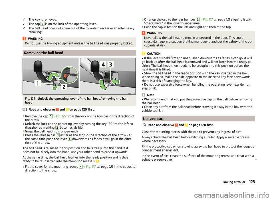
Removing the ball head
Fig. 122
Unlock the operating lever of the ball head/removing the ball
head
Read and observe
and on page 120 first.
›
Remove the cap
1
» Fig. 122 from the lock on the tow bar in the direction of
the arrow.
›
Unlock the lock on the operating lever by turning the key 180° to the left so
that the red marking
2
becomes visible.
›
Grasp the ball head from underneath.
›
Press the release pin
3
as far as the stop in the direction of the arrow - at
the same time push the lever
4
downwards as far as it will go in the direc-
tion of the arrow.
The ball head is released in this position and falls freely into the hand. If it
does not fall freely into the hand, use your other hand to push it upwards.
At the same time, the ball head latches into the ready position and is thus
ready to be re-inserted into the mounting recess »
.
›
Fit the cover for the mounting recess
4
» Fig. 117 on page 121 in the opposite
direction to the arrow.
›
Offer up the cap to the rear bumper 2
» Fig. 117 on page 121 aligning it with
“check mark” in the lower bumper area.›
Push the cap in first on the left and right and then at the top.
WARNINGNever allow the ball head to remain unsecured in the boot. This could
cause damage in a sudden braking manoeuvre and put the safety of the oc- cupants at risk.
CAUTION
■ If the lever is held firm and not pushed downwards as far as it can go, it will
go back up after the ball head is removed and will not latch into the ready po-
sition. The ball head then needs to be brought into this position before the
next time it is fitted.■
Stow the ball head in the ready position with the key inserted in the box.
When doing so, make the side opposite to the inserted key face downwards –
there is a risk of damaging the key.
■
Do not use excessive force when handling the operating lever (e.g. do not
step on it).
Note
■ We recommend that you put the protective cap on the ball before removing
the ball head.■
Clean any dirt from the ball head before stowing it away in the box with the
vehicle tool kit.
Use and care
Read and observe
and on page 120 first.
Close the mounting recess with the cap to prevent any ingress of dirt.
Always check the ball head before hitching a trailer. Apply a suitable grease where necessary.
Fit the protective cap when stowing away the ball head to protect the luggage
compartment against dirt.
In the event of dirt, clean the surfaces of the mounting recess and treat with a
suitable preservative.
123Towing a trailer
Page 126 of 197
CAUTIONApply grease to the upper part of the mounting recess. Make sure you do not
remove any grease.
Trailer
Introduction
This chapter contains information on the following subjects:
Loading a trailer
124
Towing a trailer
124
Anti-theft alarm system
125WARNINGAlways drive particularly carefully with the trailer.
Loading a trailer
Read and observe
on page 124 first.
The vehicle/trailer combination must be balanced, whereby the maximum per-
missible drawbar load must be utilised. If the drawbar load is too low, it jeop-
ardises the performance of the vehicle/trailer combination.
Distribution of the load
Distribute the load in the trailer in such a way that heavy items are located as
close to the axle as possible. Secure the items from slipping.
The distribution of the weight is very poor if your vehicle is unladen and the
trailer is laden. Maintain a particularly low speed if you cannot avoid driving
with this combination.
Tyre pressure
Correct the tyre inflation pressure on your vehicle for a “full load” » page 151,
Tyre service life .
Trailer load
The permissible trailer load must not be exceeded under any circumstan-
ces » page 176 , Technical data .
The trailer loads specified apply only to altitudes up to 1 000 metres above
mean sea level.
The engine output falls as altitude increases, as does the ability to climb.
Therefore, for every additional 1000 m in height (or part), the maximum per-
missible towed weight must be reduced by 10 %.
The towed weight comprises the actual weights of the (loaded) towing vehicle and the (loaded) trailer.
The trailer and drawbar load information on the type plate of the towing
equipment are merely test data for the towing equipment. The vehicle-specific
values are detailed in the vehicle documents.WARNING■ Do not exceed the maximum permissible axle and drawbar load and the
maximum permissible total or towed weight of the vehicle and the trailer –
there is the risk of an accident and serious injury.■
Slipping loads can significantly affect the stability and safety of the vehi-
cle/trailer combination – there is the risk of an accident and serious injury.
Towing a trailer
Read and observe
on page 124 first.
Exterior mirrors
You have to have additional exterior mirrors fitted if you are not able to see
the traffic behind the trailer with the standard rear-view mirrors. National legal
requirements must be observed.
Headlights
The front of the vehicle can be lifted when a trailer is being towed and the
headlights can dazzle other road users.
Adjust the headlight setting on the headlight range control » page 56, Head-
light beam adjustment .
Driving speed
For safety reasons, do not drive faster than 80 km/h when towing a trailer.
Immediately reduce your speed as soon as even the slightest swaying of the
trailer is detected. Never attempt to stop the trailer from “swaying” by acceler-
ating.
Brakes
Apply the brakes in good time! If the trailer is fitted with a trailer brake, apply
the brakes gently at first, then brake firmly. This will avoid brake jolts resulting
from the trailer wheels locking.
124Driving
Page 127 of 197
On downhill sections shift down a gear in good time to also use the engine as
a brake.
Engine overheating
The speed must be reduced immediately if the needle for the coolant tempera-
ture gauge moves into the right-hand area or the red area of the scale.
Stop and switch off the engine if the warning light
in the instrument cluster
starts to flash. Wait a few minutes and check the level of coolant » page 144,
Checking the coolant level .
The following guidelines must be observed » page 37,
Coolant .
The coolant temperature can be reduced by switching on the heating.WARNING■ Adapt your speed to the conditions of the road surface and to the traffic
situation.■
Improper or incorrectly connected electric cables can energise the trailer
and cause functional faults to the vehicle's entire electrical system as well
as accidents and severe injuries.
■
Work on the electrical system must only be carried out by specialist ga-
rages.
■
Never directly connect the trailer's electrical system with the electrical
connections for the tail lights or other current sources.
Note
■ After coupling the trailer and connecting up the power socket, check the rear
lights on the trailer to ensure they work.■
If there is an error in the trailer lighting system, check the fuses in the fuse
box in the dashboard » page 168.
■
If you tow a trailer frequently, you should also have your car inspected be-
tween service intervals.
■
The handbrake on the towing vehicle must be applied when coupling and un-
coupling the trailer.
Anti-theft alarm system
Read and observe
on page 124 first.
When the vehicle is locked, the alarm is activated as soon as the electrical con-
nection to the trailer is interrupted.
Always switch off the anti-theft alarm system before a trailer is coupled or un-
coupled » page 49 .
Conditions for including a trailer in the anti-theft alarm system. The vehicle is factory-fitted with an anti-theft alarm system and towing
equipment.
The trailer is electrically connected to the towing vehicle by means of the
trailer socket.
The electrical system of the vehicle and trailer is functional.
The vehicle is locked with the vehicle key and the anti-theft alarm system is activated.
Note
For technical reasons, trailers with rear LED lights cannot be connected to the
anti-theft alarm system.125Towing a trailer
Page 128 of 197
General Maintenance
Car care
Services, modifications and technical alterations
Introduction
This chapter contains information on the following subjects:
ŠKODA Original Parts
126
ŠKODA Original Accessories
127
Spoiler
127
Airbags
127
The instructions and guidelines issued by ŠKODA AUTO a.s. must be observed
when making any modifications, repairs or technical changes to your vehicle.
Compliance with these guidelines and instructions is in the interest of the
roadworthiness and technical condition of your vehicle. The vehicle will comply
with road traffic regulations following the modifications, repairs and technical
changes.
Always consult a ŠKODA Partner before buying accessories or parts, or before
carrying out any modifications, repairs or technical alterations to your vehicle.
WARNING■ Work not properly performed on your vehicle can lead to faults - there is a
risk of an accident resulting in serious injury.■
We recommend only having these modifications and technical changes
performed by a specialist garage.
■
Interference on the electronic components and their software can lead to
operational faults. This interference can also impair not directly affected
systems because of the networking of the electronic components. The op-
erational safety of the vehicle may be at significant risk and parts may suf-
fer increased wear.
■
The ŠKODA Partner cannot assume any liability for products which have
not been approved by ŠKODA AUTO a.s. even though these may be prod-
ucts with a type approval or have been approved by a nationally recognised
testing laboratory.
WARNING■ We advise you only to use ŠKODA Original Accessories and ŠKODA Origi-
nal Parts which have been expressly approved for use on your vehicle. Reli-
ability, safety and suitability for your vehicle are guaranteed with these.■
ŠKODA Original Accessories and ŠKODA Original Parts can be purchased
from a ŠKODA Partner who will also fit the purchased parts correctly.
For the sake of the environment
Technical documents regarding changes carried out on the vehicle must be
kept by the vehicle user, in order to be handed over to the recyclers later. This
ensures that vehicle recycling is in accordance with environmental regulations.
Note
Any damage caused by technical alterations made without the approval of the
manufacturer is excluded from the » Service schedule warranty.
ŠKODA Original Parts
Read and observe
on page 126 first.
We recommend the use of ŠKODA Genuine Parts for your vehicle, since these
parts are approved by ŠKODA AUTO a.s. They correspond exactly to ŠKODA
AUTO a.s. specifications in respect of design, dimensional accuracy and materi-
al and are identical to the components used in the batch production.
ŠKODA AUTO a.s. can guarantee the safety, suitability, and long life of these
products. We therefore recommend that you only use ŠKODA Genuine Parts.
ŠKODA AUTO a.s. supplies the market with a complete range of ŠKODA Genu-
ine Parts not only while the model is still in production but with wear-and-tear
parts for at least 15 years after the end of series production and with all other
vehicle parts for at least 10 years.
ŠKODA service partners are liable for any defects in ŠKODA original parts for a
period of 2 years after sale in accordance with materials defect liability under
the law unless otherwise agreed in the purchase agreement. You should keep
the confirmed warranty certificate and the receipt for these components for
this period, so that the commencement of the warranty term may be verified.
Body repairs
ŠKODA vehicles are designed so that if the body suffers damage, it is only nec-
essary to replace those parts which are in fact damaged.
126General Maintenance
Page 129 of 197
Before you decide to have damaged body parts replaced, however, you should
first contact your specialist garage to determine whether or not such parts can
also be repaired. Repairs to body parts are usually cheaper.
ŠKODA Original Accessories
Read and observe
on page 126 first.
You should note the following if you wish to fit accessories to your vehicle:
We recommend that you use ŠKODA Genuine Accessories in your vehicle.
ŠKODA AUTO a.s. offers a warranty on the reliability, safety and suitability for
your particular vehicle of these accessories. Although we constantly monitor
the market, we are not able to assess or offer a warranty on other products
even though in some instances such products may have a type approval or
may have been approved by a nationally recognised approval authority.
All accessory products go through a fastidious process of technical develop-
ment (technical tests) and quality inspection (customer tests), and only if all
tests are positive does the product become a ŠKODA Genuine Accessory.
Our ŠKODA Genuine Accessories service also provides expert advice and pro-
fessional fitting if requested by the customer.
ŠKODA Service Partners are liable for any defects in ŠKODA Genuine Parts for a period of 2 years after installation or delivery in accordance with materials de-
fect liability legislation, unless otherwise agreed in the purchase contract or in
any other agreements. You should keep the confirmed warranty certificate and
the receipt for these accessories for this period, so that the commencement of
the warranty term may be verified.
In addition, ŠKODA Service Partners also stock a range of suitable car care
products as well as those parts which are subject to natural wear and tear,
such as tyres, batteries, bulbs and wiper blades.
Note
The accessories authorized by ŠKODA AUTO a.s. will be offered by the ŠKODA
Partners in all countries where ŠKODA AUTO a.s. has a sales and service net- work. This will usually be in the form of a printed catalogue of Original ŠKODA
Accessories, in the form of separate printed brochures or in the form of offers
for ŠKODA Genuine Accessories on the ŠKODA Partner's website.Spoiler
Read and observe
on page 126 first.
The following instructions shall be observed if your new vehicle is equippedwith a spoiler fitted to the front bumper in combination with the spoiler on the
tailgate.
› For safety reasons the vehicle must only ever be equipped with a spoiler on
the front bumper in combination with the associated spoiler on the tailgate.
› A spoiler cannot be fitted alone on the front bumper nor in combination with-
out a spoiler on the tailgate or in combination with an inappropriate spoiler
on the tailgate.
› We recommend that you consult a ŠKODA Service Partner for any repairs, re-
placement, fitting or removal of spoilers.
WARNINGWork not properly performed on the spoilers on your vehicle can result in
faults - there is a risk of an accident and serious injury.
Airbags
Read and observe
on page 126 first.
The system components for the airbag system may be found in the front
bumper, doors, front seats, the roof lining or in the bodywork.
WARNINGAny work on the airbag system including the installation and removal of
system components due to other repair work (e.g. removal of the steering
wheel) must only be carried out by a specialist garage.■
Adjustments, repairs and modifications which have been carried out un-
professionally can cause damage, operational faults, and can also seriously
impair the effectiveness of airbag system – there is the risk of an accident
and fatal injury.
■
The airbag system must be replaced if an airbag has been deployed. Air-
bag modules cannot be repaired.
127Car care
Page 130 of 197
WARNINGObserve the following instructions for the airbag system.■It is prohibited to tamper with individual parts of the airbag system as this
might result in the airbag being deployed.■
Never install any airbag parts into the vehicle that have been removed
from old cars or have been recycled.
■
Never fit damaged airbag parts to a vehicle. The airbags may then not be
triggered properly or not at all in the event of an accident.
■
No modifications of any kind must be made to parts of the airbag system.
WARNING■ A change in the suspension of the vehicle including the use of non-ap-
proved wheels and tyre combinations can alter the functioning of the air-
bag system - there is a risk of accident and fatal injury.■
Never make any changes to the front bumper or bodywork.
Washing the car
Introduction
This chapter contains information on the following subjects:
Washing by hand
128
Automatic car wash systems
129
Washing with a high-pressure cleaner
129
The best protection for your vehicle against harmful environmental influences
is frequent washing.
How often the vehicle should be washed depends, for example, on the follow-
ing factors.
› Frequency of use.
› Parking situation (garage, under trees, etc.).
› Season of the year.
› Weather conditions.
› Environmental influences.
The longer insect residues, bird droppings, tree sap, road and industrial dust,
tar, soot particles, road salt and other aggressive deposits remain adhering to
the paintwork of your vehicle, the more detrimental their destructive effect
can be. High temperatures, such as those caused by intensive sun's rays, ac-
centuate this caustic effect.
It is essential to also thoroughly clean the underside of the vehicle at the end
of the winter.WARNING■ Washing your vehicle in the winter: water and ice in the brake system can
affect the braking efficiency – there is the risk of an accident.■
Only wash the vehicle when the ignition is switched off – there is the risk
of an accident.
CAUTION
Do not wash your vehicle in bright sunlight – there is a risk of paint damage.
For the sake of the environment
Only wash the vehicle at washing bays intended for this purpose.
Washing by hand
Read and observe
and on page 128 first.
Soften the dirt with plenty of water and rinse as much as you can of this off.
Clean the vehicle with a soft sponge, a washing glove or a washing brush .
Work from the top to the bottom - starting with the roof.
Only use a car shampoo for stubborn dirt.
Wash out the sponge or washing glove thoroughly at short intervals.
Clean wheels, door sills and similar parts last. Use a second sponge for such
areas.
Give the vehicle a good rinse after washing it and dry it off using a chamois
leather.
CAUTION
■ When washing the car by hand, protect your hands and arms from sharp-
edged metal parts (e.g. when cleaning the underfloor, the inside of the wheel
housings or the wheel trims, etc.) - There is a risk of cuts!■
Only apply slight pressure when cleaning the vehicle's paintwork.
128General Maintenance