battery capacity SKODA FABIA 2014 2.G / 5J Owner's Manual
[x] Cancel search | Manufacturer: SKODA, Model Year: 2014, Model line: FABIA, Model: SKODA FABIA 2014 2.G / 5JPages: 197, PDF Size: 13.56 MB
Page 68 of 197
›Release the lever 1 and push the seat until the lock clicks into place.
Adjusting height of seat›
To lift the seat, pull or pump lever
2
» Fig. 55 upwards.
›
To lower the seat, push or pump the lever
2
downwards.
Adjusting the angle of the seat backrest
›
Relieve the load on the seat backrest (do not lean on it), pull the lever
3
» Fig. 55 towards the rear and set the desired angle of the seat backrest
with the back.
›
After releasing the lever
3
, the seat backrest will remain in the set position.
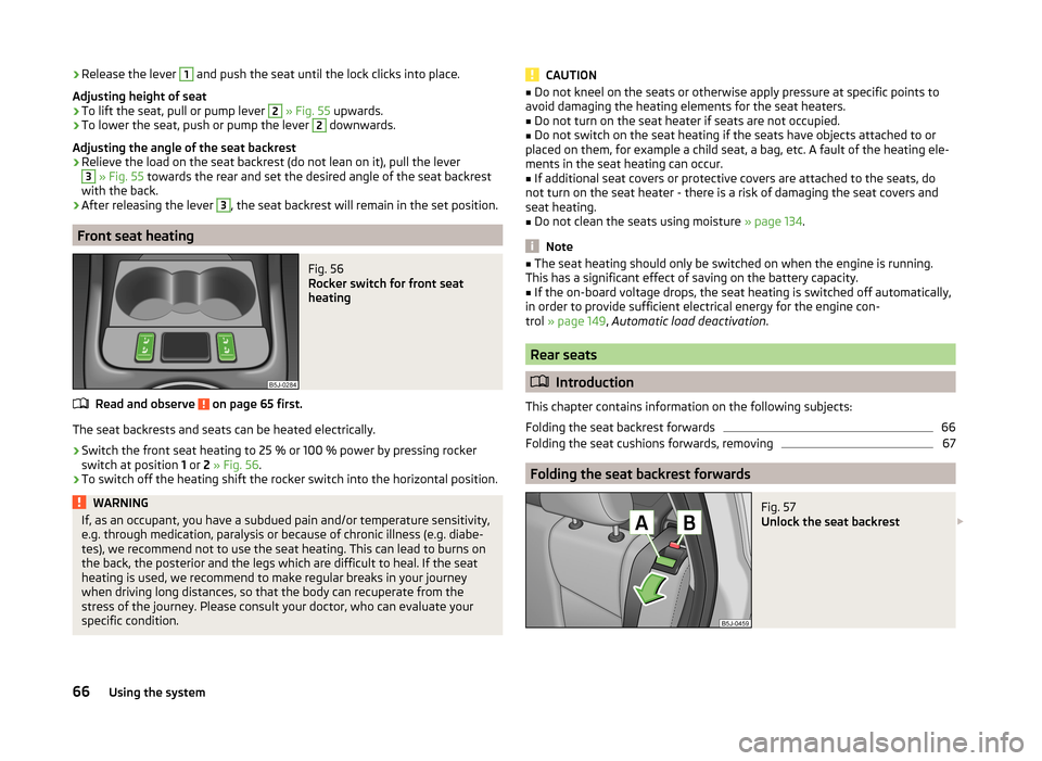
Front seat heating
Fig. 56
Rocker switch for front seat
heating
Read and observe on page 65 first.
The seat backrests and seats can be heated electrically.
›
Switch the front seat heating to 25 % or 100 % power by pressing rocker
switch at position 1 or 2 » Fig. 56 .
›
To switch off the heating shift the rocker switch into the horizontal position.
WARNINGIf, as an occupant, you have a subdued pain and/or temperature sensitivity,
e.g. through medication, paralysis or because of chronic illness (e.g. diabe-
tes), we recommend not to use the seat heating. This can lead to burns on
the back, the posterior and the legs which are difficult to heal. If the seat
heating is used, we recommend to make regular breaks in your journey
when driving long distances, so that the body can recuperate from the
stress of the journey. Please consult your doctor, who can evaluate your
specific condition.CAUTION■ Do not kneel on the seats or otherwise apply pressure at specific points to
avoid damaging the heating elements for the seat heaters.■
Do not turn on the seat heater if seats are not occupied.
■
Do not switch on the seat heating if the seats have objects attached to or
placed on them, for example a child seat, a bag, etc. A fault of the heating ele-
ments in the seat heating can occur.
■
If additional seat covers or protective covers are attached to the seats, do
not turn on the seat heater - there is a risk of damaging the seat covers and
seat heating.
■
Do not clean the seats using moisture » page 134.
Note
■
The seat heating should only be switched on when the engine is running.
This has a significant effect of saving on the battery capacity.■
If the on-board voltage drops, the seat heating is switched off automatically,
in order to provide sufficient electrical energy for the engine con-
trol » page 149 , Automatic load deactivation .
Rear seats
Introduction
This chapter contains information on the following subjects:
Folding the seat backrest forwards
66
Folding the seat cushions forwards, removing
67
Folding the seat backrest forwards
Fig. 57
Unlock the seat backrest
66Using the system
Page 121 of 197
If after stopping the car, the message UNABLE TO START STOP appears in the
segment display or in the MAXI DOT display the check mark » Fig. 115 , then
the conditions for automatic engine shutdown are not met.
Running the engine is essential, for example, for the following reasons.
› The engine temperature for the proper function of the system has not yet
been reached.
› The charge state of the vehicle battery is too low.
› The current consumption is too high.
› High air-conditioning or heating capacity (high fan speed, big difference be-
tween the desired and actual indoor temperature).
Note
■ If the vehicle remains outdoors for a long time in minus temperatures or in
direct sunlight, it can take several hours until the internal temperature of the
vehicle battery reaches a suitable temperature for proper operation of the
START STOP system.■
If the driver's seat belt is removed for more than approx. 30 seconds or the
driver's door is opened during stop mode, the engine will have to be started
manually.
■
After manual engine start, the automatic engine shutdown can take place
only when a minimum distance required for the system function has been cov-
ered.
Operation
Read and observe
on page 118 first.
In compliance with the operating conditions, automatic engine shutdown / au-
tomatic engine start takes place as described.
Automatic engine shut down
›
Stop the vehicle.
›
Shift the gear lever to Neutral.
›
Release the clutch pedal.
Automatic engine shutdown takes place, segment display shows START STOP
ACTIVE or a check mark appears in the MAXI DOT display
» Fig. 115 on
page 118 .
Automatic engine start
›
Depress the clutch pedal.
The automatic start procedure takes place again.
System conditioned automatic start-up
Read and observe
on page 118 first.
When the engine is off, the system can automatically start the engine before
the desired journey continues. The possible reasons for this are, for example:
› The vehicle has begun to roll, e.g. on a slope.
› The brake pedal has been actuated several times.
› The current consumption is too high.
Manually deactivating/activating
Fig. 116
Button for the START-STOP sys-
tem
Read and observe on page 118 first.
Deactivate/activate
›
Press the button
» Fig. 116 .
When start-stop mode is deactivated, the warning light in the button lights up.
Note
If the system is automatically deactivated when the engine is turned off, then
the automatic start process takes place.
Information messages
Read and observe
on page 118 first.
The messages and information are shown in the instrument cluster display. Start the engine manually.
START MANUALLY
One of the conditions for automatic engine start is not satisfied or the driver's
seat belt is not fastened. The engine must be started manually.
119Assist systems
Page 142 of 197

Closing›Lift the bonnet slightly and unhook the bonnet support. Press the bonnet
prop into the bracket provided.›
Let the bonnet drop into the lock carrier lock from a height of around 20 cm –
do not push it in .
WARNINGCheck that the bonnet is closed properly.
CAUTION
Never open the bonnet by the locking lever » Fig. 124.
Engine compartment overview
Fig. 126
Principle sketch: Engine compartment
Read and observe
and on page 138 first.
Explanation of graphic » Fig. 126
Coolant expansion reservoir
144
Windscreen washer fluid reservoir
140
Engine oil filler opening
143
Engine oil dipstick
142
Brake fluid reservoir
145
Vehicle battery
145123456NoteThe location of the inspection points in the engine compartment of petrol and
diesel engines is practically identical.
Radiator fan
Read and observe
and on page 138 first.
The radiator fan is powered by an electric motor. Operation is controlled ac-
cording to the temperature of the coolant.
WARNINGThe fan can intermittently continue to run for approximately 10 minutes af-
ter the ignition is switched off.
Windscreen washer system
Fig. 127
Engine compartment: Wind-
screen washer fluid reservoir
Read and observe and on page 138 first.
The windscreen washer fluid reservoir is located in the engine compart-
ment » Fig. 127 .
This contains the cleaning fluid for the windscreen or rear window and for the
headlight cleaning system.
The capacity of the reservoir is about 3.5 litres or about 5.4 litres on vehicles
that have a headlight cleaning system 1)
.
1)
In some countries, 5.4 ltr. applies for both variants.
140General Maintenance
Page 150 of 197
We therefore recommend that you have the battery checked and, if necessary,
recharged by a specialist garage before the start of the winter.
CAUTION
For technical reasons, on vehicles with the description “AGM”, the electrolyte
level cannot be checked.
Note
The battery electrolyte level is also periodically checked by a specialist garage
as part of the Inspection Service.
Charging
Read and observe
and on page 146 first.
A properly charged vehicle battery is essential for reliably starting the engine.
›
Switch off the ignition and all of the electrical components.
›
Only when performing a “quick-charge”, disconnect both battery cables (first
“negative”, then “positive”).
›
Attach the terminal clamps of the charger to the battery terminals (red =
“positive”, black = “negative”).
›
Plug the mains cable of the charger into the power socket and switch the
charger on.
›
Once charging is complete: Switch off the charger and remove the mains ca-
ble from the power socket.
›
Only then disconnect the charger's terminal clamps.
›
Reconnect the cables to the battery (first “positive”, then “negative”).
It is not necessary to disconnect the battery cables if you are recharging the
vehicle battery using low amperages (for example from a mini-charger). Refer
to the charger manufacturer's instructions .
A charging current of 0.1 multiple of the total vehicle battery capacity (or low-
er) must be used until full charging is achieved.
Both cables must be disconnected before charging the battery with high
amperages, known as “ rapid charging”.
The vent plugs of the vehicle battery should not be opened for charging.
WARNING“Quick-charging” the vehicle battery is dangerous and requires a special
charger and specialist knowledge.CAUTIONOn vehicles with the START/STOP system, the pole terminal of the charger
must not be connected directly to the negative terminal of the vehicle battery,
but only to the engine earth » page 166, Jump-starting in vehicles with the
START-STOP system .
Note
We therefore recommend that vehicle batteries be rapid charged by a special-
ist garage.
Replacing
Read and observe
and on page 146 first.
The new vehicle battery must have the same capacity, voltage, current and thesame size as the original battery. Suitable vehicle battery types can be pur-
chased from a specialist garage.
We recommend that the battery is replaced by a specialist garage, where the
new vehicle battery will be installed properly and the original battery will be
disposed of in accordance with national regulations.
Disconnecting or reconnecting
Read and observe
and on page 146 first.
The following functions are initially deactivated or are no longer able to oper-
ate faultlessly after the vehicle battery has been disconnected and reconnec-
ted.
OperationOperating measureElectrical power window (operational faults)» page 53Enter the radio/navigation system code
number» User manual of the radio
or » user manual of the naviga-
tion systemSetting the clock» page 28Data in the multifunction display are de-
leted.» page 29
Note
We recommend having the vehicle checked by a specialist garage to ensure
the full functionality of all electrical systems.148General Maintenance
Page 151 of 197
Automatic load deactivationRead and observe
and on page 146 first.
The vehicle voltage control unit automatically prevents the battery from dis-
charging when the battery is subjected to heavy loads. This may be noticed
from the following.
› The idling speed is raised to allow the generator to deliver more electricity to
the electrical system.
› Where appropriate large convenience consumers, e.g. seat heaters, rear win-
dow heaters, have their power limited or shut off completely if necessary.
CAUTION
■ Despite such intervention by the vehicle electric system management, the
vehicle battery may be drained. For example, when the ignition is switched on
a long time with the engine turned off or the side or parking lights are turned
on during longer parking.■
Consumers which are supplied via a 12 V socket can cause the vehicle battery
to discharge when the ignition is switched off.
Note
Driving comfort is not disrupted by any shutting off of consumers. Often the
driver is not aware of it having taken place.Wheels
Tyres and rims
Introduction
This chapter contains information on the following subjects:
Tyre service life
151
Explanation of the tire labelling
152
New Wheels
152
Unidirectional tyres
154
Tyre pressure monitor
154
Spare and back-up wheel
155
Full wheel trim
156
Wheel bolts
156
Wheel bolts
156WARNINGNational legal requirements must be observed for the use of tyres.WARNINGInstructions for the use of tyres■During the first 500 km, new tyres do not offer optimum grip and appro-
priate care should therefore be taken when driving – there is the risk of an
accident.■
Only use radial tyres of the same type, size and tread pattern on all four
wheels.
■
For safety reasons, do no replace tyres individually.
■
Never exceed the maximum permissible load bearing capacity for fitted
tyres – risk of accident!
■
Never exceed the maximum permissible speed for fitted tyres – risk of ac-
cident!
■
Incorrect wheel alignment at the front or rear impairs handling – there is
the risk of an accident.
149Wheels
Page 167 of 197
WARNING■A discharged vehicle battery may already freeze at temperatures just be-
low 0 °C. If the battery is frozen, do not jump start with the battery of an-
other vehicle – there is a risk of explosion.■
Pay attention to the warning instructions relating to working in the en-
gine compartment » page 138.
■
The non-insulated parts of the terminal clamps must never touch each
other – there is a risk of short circuit.
■
The jump-start cable connected to the positive terminal of the battery
must not come into contact with electrically conducting parts of the vehicle
– there is a risk of short circuit.
■
Do not clamp the jump-start cable to the negative terminal of the dis-
charged battery. There is the risk of detonating gas seeping out the battery being ignited by the strong spark which results from the engine being star-
ted.
■
Route the jump-start cables so that they cannot be caught by any rotat-
ing parts in the engine compartment.
■
Do not bend over the battery – there is a risk of caustic burns.
■
The vent screws of the battery cells must be tightened firmly.
■
Keep any sources of ignition (naked flame, smouldering cigarettes, etc.)
away from the battery – risk of explosion!
■
Never jump-start vehicle batteries with an electrolyte level that is too low
– risk of explosion and caustic burns.
CAUTION
■ There must not be any contact between the two vehicles otherwise current
may flow as soon as the negative terminals are connected.■
The discharged battery must be properly connected to the system of the ve-
hicle.
■
We recommend you buy jump-start cables from a car battery specialist.
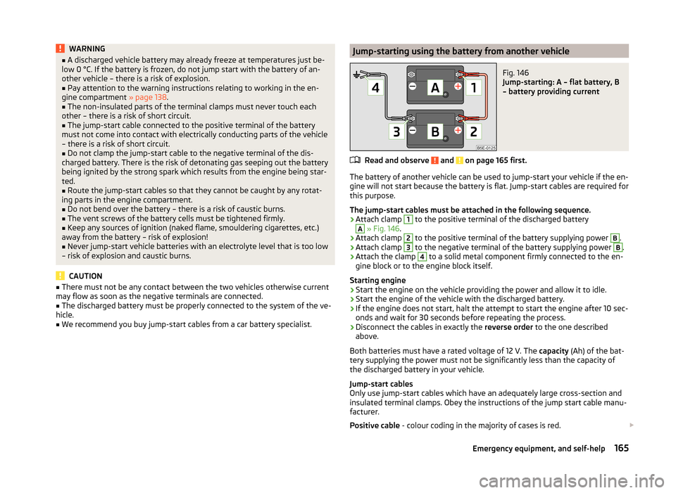
Jump-starting using the battery from another vehicleFig. 146
Jump-starting: A – flat battery, B
– battery providing current
Read and observe and on page 165 first.
The battery of another vehicle can be used to jump-start your vehicle if the en-
gine will not start because the battery is flat. Jump-start cables are required for
this purpose.
The jump-start cables must be attached in the following sequence.
›
Attach clamp
1
to the positive terminal of the discharged battery
A
» Fig. 146 .
›
Attach clamp
2
to the positive terminal of the battery supplying power
B
.
›
Attach clamp
3
to the negative terminal of the battery supplying power
B
.
›
Attach the clamp
4
to a solid metal component firmly connected to the en-
gine block or to the engine block itself.
Starting engine
›
Start the engine on the vehicle providing the power and allow it to idle.
›
Start the engine of the vehicle with the discharged battery.
›
If the engine does not start, halt the attempt to start the engine after 10 sec-
onds and wait for 30 seconds before repeating the process.
›
Disconnect the cables in exactly the reverse order to the one described
above.
Both batteries must have a rated voltage of 12 V. The capacity (Ah) of the bat-
tery supplying the power must not be significantly less than the capacity of
the discharged battery in your vehicle.
Jump-start cables
Only use jump-start cables which have an adequately large cross-section and
insulated terminal clamps. Obey the instructions of the jump start cable manu-
facturer.
Positive cable - colour coding in the majority of cases is red.
165Emergency equipment, and self-help
Page 189 of 197
De-icing rear window61
Deactivating airbags18
Decorative films131
Delayed locking of the boot lid see boot lid
51
Diesel refer to Fuel
137
Diesel fuel Operation in winter
137
Diesel particulate filter39
display messages39
Digital clock28
Dipstick142
Display Service interval
32
Distance driven28
Door Child safety lock
44
Closing44
Indicator light for an open door36
Opening44
Doors Emergency locking
45
driving emissions
177
fuel consumption177
Driving Abroad
113
Driving through water on streets112
Maximum speed179
Driving economically Economical gear changing
109
Driving through water112
E
Economical and environmentally friendly driv- ing
109
Economical driving Anticipation in driving109
Ballast111
Driving at full throttle110
Idling110
Regular maintenance111
Saving energy111
Short distances110
Tyre pressure110
EDS115
Electrical power windows Button in the driver's door
51, 52
Button in the rear door52
Central locking system53
Electric power windows Operational faults
53
Electric sliding/tilting roof53
Electronic Differential Lock115
Electronic immobilizer101
Emergency Changing a wheel
159
Hazard warning light system59
Jump-starting164, 165
locking of the doors45
Selector lever-unlocking108
Sliding/tilting roof55
Towing the vehicle166
Towing the vehicle using the tow hitch167
Tyre repair162
Unlocking the boot lid51
Emergency equipment Fire extinguisher
158
First aid kit158
Jack159
Vehicle tool kit159
Warning triangle158
Emissions177
Engine Running in
108
Starting and stopping the engine101
Starting the engine102
Switching off the engine102
Engine compartment138
Brake fluid145
Coolant144
Overview140
Vehicle battery145
Engine number176
Engine oil141
Capacity141
Changing143
Checking142
Replenishing143
Specifications141
Warning light36
Engine revolutions counter27
Environment109
Environmental compatibility111
Environmentally friendly driving109
ESC Function
114
warning light38
F
Films
131
Fire extinguisher158
First aid kit158
Flashers57
Fog lights58
Footmats104
see Footmats104
Front airbag15
Front seats65
Fuel135
Diesel137
Fuel gauge27
gauge27
refer to Fuel135
187Index
Page 193 of 197

TransportBoot68
Roof rack system76
Transporting children safely19
Turn signals57
Two-way radio systems92
Tyre load-bearing capacity see Wheels
152
Tyre pressure monitor Setting
154
Tyre repair Check pressure
164
Preparations163
Sealing and inflating the tyre164
Tyres149
Pressure151
Sizes151
Wear indicator151
U
Underbody protection
132
Underbody waxing132
Unleaded petrol113
unlock Central locking system
47
Unlocking Remote control
48
without central locking45
Unlocking and locking42
USB99
Useful equipment77
12-volt power outlet79
Ashtray78
Car park ticket holder80
Cigarette lighter79
Clothes hood80
Cupholders78
Using the selector lever105
V
Variable loading floor
72
Dividing the luggage compartment72
Removing and refitting72
Vehicle battery Automatic load deactivation
149
Charging148
Checking the battery electrolyte level147
Cover147
Disconnecting and reconnecting148
Operation in winter147
Replacing148
Safety instructions145
Vehicle care Alcantara
134
Care of the interior132
Decorative films131
Fabrics134
Polishing130
Rubber seals130
Seat covers134
Synthetic leather134
Underbody waxing132
Vehicle exterior care129
Waxing130
Vehicle data sticker176
Vehicle dimensions178
Vehicle Identification Number (VIN)176
Vehicle key42
Vehicle status see Auto Check Control
34
Vehicle tool kit159
Visors61
W
Warning lights
35
Warning symbols see warning lights
35
Warning triangle158
Washing126
Automatic car wash system129
by hand128
Chrome parts130
High-pressure cleaner129
Water Driving through
112
Waxing See Vehicle care
130
Wheel bolts Anti-theft wheel bolt
162
Caps156
Loosening and tightening161
Wheels Back-up wheel
155
Bolts156
Changing159
Full trim156
General information149
Load index152
Snow chains157
Spare wheel155
Speed symbol152
Storing wheels151
Swapping wheels around151
Tire size152
Tyre pressure151
Tyre service life151
Tyre wear indicator151
Unidirectional tyres154
Wheel sizes151
Winter tyres156
Window convenience operation53
Windows131
Deicing131
See Electrical power windows51
Window wipers Replacing the rear window wiper blade
63
Windscreen Deicing
131
191Index